1
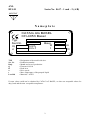
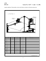
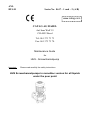
ANL HUS-B Series No. 8617 – 1 und – 2 (A/B) www.catag.com CATAG AG BASEL Auf dem Wolf 19 CH-4052 Basel Tel: 061 373 73 73 Fax: 061 373 73 70 Maintenance Guide for HUS - Screwchannelpump Important: Please read carefully the safety instructions HUS Screwchannelpumps in monobloc version for all liquids under the pour point ANL HUS-B Series No. 8617 – 1 und – 2 (A/B) IMPORTANT Nameplate CATAG AG BASEL CH-4053 Basel Typ Ser.Nr. Q n TYP Ser. Nr. Bauj. Q H n t Leerfeld m3/h min-1 Bauj. H t m °C : Designation of the model with size. : Production number. : Month and year of production. : Flowrate in m3/h : Head in m : Drive speed. : Max. temperature of the pumped liquid : Materials / ATEX. If some values could not be obtained by CATAG AG BASEL, we then set acceptable values for duty, head and the max. acceptable temperature. 2 ANL HUS-B Series No. 8617 – 1 und – 2 (A/B) CONTENTS Page 1.0 Introduction 1.1 1.2 A E Nameplate Contents Arrival of shipment Erection 2 3 4 4 2.0 Installation and start-up 4 F Starting G Maintenance 4 5 3.0 Servicing 6 H Instruction for assembly Fault finding 6 9 Attachments: (depending on agreements, one or several of the following items) Cutaway of pump Spare parts list Performance curve For a correct performance you may have to read these instructions carefully. Damages or at least reduced live-time will result, if you do not respect these guides. Read also the danger notices carefully. 3 ANL HUS-B Series No. 8617 – 1 und – 2 (A/B) A Arrival of shipment Upon arrival of shipment check whether order is complete and safe. File any claim i m m e d i a t e l y to the Shipping agent otherwise your rights will be waived. B Check oil filling The pump unit is supplied with oil filling and ready for operation. Check whether the oil is up to the lower edge of the motor chamber fill opening and of the seal chamber (see spares drawing and chapter G2). Small oil leakage upon arrival is irrelevant, it will disappear after a short period of operation. C Operating conditions • Adhere to general regulations and rules for accident prevention and for protection against explosion in sewage installations. In rooms where there is danger of explosions, only pump units of explosion-proof design must be installed. • The pumps - Sewage pumps with screw channel impeller are principally suitable for pumping sewage and sewage sludge up to a temperature of 40°C, which are not corrosive for iron (cast iron design), for automatic intake, i.e. the pumps are either submerged or receive the flow through a suction line. The operating conditions which batch pumps is especially designed for are described separately in the HUS catalogue. • 15 starts per hour are permitted. Flow velocity in the pipe line should be at least 0,8 m/sec. D Erection Erect pump unit in position, connecting it without distortion, tension and vibration to the pressure line. (suction line) in case of dry erection make sure that suction line rises towards the pump and that it is mounted absolutely tight. Respect general rules for arrangement of suction line. For well sump erection of pump by means of suspension and lifting device, consult the respective directions for installation (enclosed). 4 ANL HUS-B Series No. 8617 – 1 und – 2 (A/B) E Electric connection Have the pump unit connected by an expert electrician in accordance with all rules in force. Compare the line voltage and the type of current with the data on the nameplate. Connect through a motor starter, preferably with ampere-meter and delayed action fuse. The adjustment value of Ihe motor starter and the size of the fuse are shown on the characteristics chart. Admissible voltage fluctuation ±-5%. See enclosed connection diagram. F Starting The pump must only be started after installation. Any work at the pump must only be made after cutting out the electric supply and after standstill of all rotating parts. Before starting: 1) Flood the pump unit. The pump volute must be completely filled with the pumped fluid and air has to be allowed to escape (by means of air plug at discharge piece or by lifting the non-return valve). 2) Open sluice valves, if any. 3) Check adjustment of float switches (the lowest water level has to be above the top of the pump volute). At the moment of starting and immediately after starting: 1) Check whether direction of rotation is correct. • Clockwise, seen from the top . Starting jerk of pump unit is anti-clockwise, • Maximum capacity/head (compare by interchanging two phases). Wrong direction of rotation will result in noisy operation (cornpare by interchanging two phases). To change the direction of rotation, interchange two phases of the line, such as L, against L2 or L3 against L2. 2) Check current consumption and the operation of the pump. 3) In Case of trouble see -K- "trouble shooting". Instruction for working at the pump: Any work at the pump must only be made after cutting out electricity supply and after standstill of all rotating parts. The oil in the sealing chamber and in the motor may be under pressure. Consequently, loosen the drain and fill plug very cautiously and slowly. Remove plugs orify after complete compensation of pressure. 5 ANL HUS-B Series No. 8617 – 1 und – 2 (A/B) G Maintenance The pump will work without maintenance throughout a long time. Controls: 1) Check current consumption from time to time, by means of an ampere-meter. Constant amps. means normal operation. Occasional current fluctuations are caused by solids in the pump fluid as they pass the pump. 2) Occasionally, especially if the pump unit is new, or within one week after mounting a new mechanical shaft seal respectively a new shaft sealing, the oil level in the motor casing and seal chamber should be checked. lt must reach the lower edge of the fill opening. For the types: B an BH, the oil level can be seen at the inspection glass at the motor casing. An inclined position may show insufficient oil level. Replenish oil after a small leakage. If the leakage is considerable it is necessary to check the mechanical shaft seals (see H 7). Be sure not to forget the washers for the plugs. 3) In case of normal operation a thorough control should be made at least once a year. If the water is very muddy or sandy, repeat this check at shorter intervals. a) Oil control for presence of mud and water (see G 2). Methods: by maintenance kit (see instructions in the kit). without maintenance kit: Drain oil from motor casing and seal chamber into se parate transparent vessels and check whether it contains any impurities or water. If the oil contains a considerable amount of water, check the mechanical shaft seal. Replace oil. For oil quantity and quality see spares list. b) Mechanical shaft seals The contact surfaces of the seal have to be shining and without cracks, the O -rings and their seats have to be perfect and clean. Otherwise replace the mechanicat shaft seal. c) The condition of the contact surfaces of the compound mechanical shaft seals can be checked in the works only. However, in order to evaluate possibility of further use of the shaft seal while the shaft seal is still installed, the following has to be done: - Remove the motor with the impeller from the pump casing. - Remove the impeller. - Thereafter proceed according to sheet: 'Instructions for assembly of shaft sealing, series H, chapter "Pressure testing of shaft sealing". 6 ANL HUS-B Series No. 8617 – 1 und – 2 (A/B) d) Pump parts - Impeller, pump casing, suction parts, neck ring, mobile ring and cooling flange of motor are to be checked for possible wear. Replace defective parts. An increased gap by wear will reduce the capacity of the pump. - in case of pumps with channel impeller between impeller resp. mobile ring and neck ring, - in case of pumps with screw channel impeller between impeller and suction piece. In case of a 2 mm gap on one side for pumps without channel impeller a replacement is necessary. In case of pumps with screw channel impeller the play between impeller and suction piece can be reduced by omitting spacer shims. e) Ball bearings have permanent lubrication and do not require any maintenance. In case of noisy or heavy operation of shaft (try to turn by hand) it is required to overhaul the motor H Assembly Instructions Disconnect current before any disassernbly. 1) Drain oil from seal chamber before removing the following parts: impeller, lower mechanical shaft seal and for smaller pumps the pump casing. 2) Drain oil from the motor casing and the oil chamber before removing: cooling flange or sealing flange, upper mechanical shaft seal or shaft sealing, seal casing, ball bearing and motor casing. 1) When dismantling pump or motor parts protect the centering surfaces (tits), contact surfaces, sealing; surfaces and the seals against damage. Even little scratches or blows may cause disalignment and leakage. 2) Stuck impellers can be removed by an impeller extractor or by 2 levers. Help by alternating light blows of a rubber hammer. Take care not to damage the mechanical shaft seal at the impeller hub. 3) For replacement of neck ring or counter ring remove same by extraction, light blows or turning, according to the tools which are available. Be careful not to damage the fitting surface. 4) Mechanical shaft seals have to be handled with great care and they must be protected against damage. Scratches, tricks or blows at the sealing surfaces will cause leakage. 7 ANL HUS-B Series No. 8617 – 1 und – 2 (A/B) 5) Prior to any assembly, clean all parts thoroughly. Motor parts have to be free from moisture, otherwise the winding and ball bearings may get damaged. Foreign matter, blows and scratches at centering, fitting and sealing surfaces will cause disalignment and leakage of the parts O-rings have to be replaced by all means. They must be fitted without distortion and it will be of advantage to rub them slightly with soap water. Oil filling of motor casing and seal chamber his to be made in vertical or horizontal position of the motor, depending an the position of the filling holes. A filling in inclined position could result in a wrong filling quantity. Correct oil quantity is always to lower edge of fill opening. An air cushion must be left above. Do not forget the washers of the plugs. For oil quality see spares list. 8 ANL HUS-B Series No. 8617 – 1 und – 2 (A/B) Fault finding The following list shows possible problems and in the second part are the indications for fault finding. The figure shows the possible causes and remedies. Problems possible items Motor overload Duty or discharge pressure to low No discharge pressure Unstable flow or discharge pressure Noise and vibrations The pump is clogged Overheated pump To much wear Lekage on seal 8,9,13 1,2,4,5,7,9,10,17,19 2,3,6,18 1,2,4,5,6,9 2,4,5,6,7,8,9,10,13,14,15 9,10,13,15 8,9,10,13,15 4,5,10,15 11,12,16 Error point Solution 1 2 Wrong rotation sense NPSH to low 3. 4. 5. 6. 7. 8. pump is empty Cavitation Pump primes air Suction pipe is clogged Discharge pressure too high Flow rate too high 9. 10. 11. 12. 13. Viscosity to high Liquid temperature to high worn or damaged shaft seal O-Ring not compatible with liquide Impeller "frets" with housing 14. Tension in suction pipe 15. 16. 17. 18. Spring of mech. seal is weak Pump speed to low Suction valve closed Not enough pressure on discharge Change 2 phases Increase NPSH of the installation Set feed source higher Install pump in lower point Increase evaporation point Increase diameter of suction pipe Reduce length and complexity of suction pipe clean and fill up Increase suction pressure Check suction pipe and all connections Check suction pipe or filter if there is one installed If applicable, increase dischard pipe diametre Reduce flow rate: -Reduce impeller size -Reduce pump speed Reduce viscosity by heating the liquid for ex. Reduce temperature by cooling Replace shaft seal Replace O-Ring in a better quality. Check with supplier. -Reduce temperature -Reduce suction pressure -Adjust clearance between housing and impeller Mount all pipes in a way that no efforts result on pump or pipe. Follow maintenance guide Increase speed Check valve and open it Increase pressure Increase impeller size Increase speed If the problems persist, please contact your distributor or CATAG AG 9 ANL HUS-B Series No. 8617 – 1 und – 2 (A/B) Recommended Spare Parts We suggest to stock a complete kit of O-rings and a complete set of mech. seals. In April 2003 CATAG AG BASEL 10 ANL HUS-B Series No. 8617 – 1 und – 2 (A/B) Lubricating instructions Fill up to shown levels. 11 ANL HUS-B Series No. 8617 – 1 und – 2 (A/B) Impeller adjusting. Please add or remove shift-disks to obtain the following clearences. 12 ANL HUS-B Series No. 8617 – 1 und – 2 (A/B) 13 ANL HUS-B Series No. 8617 – 1 und – 2 (A/B) 14 ANL HUS-B Pos Nr. 1 2 3 4 5 6 7 8 9 10 11 12 13 14 15 16 17 18 19 20 21 22 23 24 25 26 27 28 29 30 31 32 33 34 35 36 37 38 39 40 Teile Bezeichnung 90 Series No. 8617 – 1 und – 2 (A/B) Part name Pumpengehäuse Schraubenkanalrad Zylinderschraube Federring Welle Runddichtung Dichtungsflansch Sechskantschraube Federring Bestell-Nr. Order No. 51.11933 S 80-12 M 10x60 10 DIN 7980 S 80-25 5/205/215 S 80-94 M 10x30 DIN 933 10 DIN 127B Distanzscheibe Lagerflansch Rillenkugellager 11x2 S100-13 6307 2RS spacer disc bearing flange grooved ball bearing Sicherungsring A35 DIN 471 safety ring Sicherungsring J80 DIN 472 safety ring Stopfen Wellendichtung Hartmetall Wellendichtung Kohle/Chrom Sicherungsring Sechskantschraube Federring GF 292 R 1/4" D=28 D=28 AV 28 M8x30 DIN 933 8 DIN 127B plug shaft sealing special shaft sealing safety ring hexagon bolt spring ring Runddichtung 3.53/142.2 o-ring Motorflansch 90/100 Zylinderschraube Federring S 80-24 M10x30 DIN 912 10 DIN 7980 motor flange cylinder head screw spring ring Grundplatte BH BG80-04 base plate BH pump casing screw type impeller cylinder head screw spring ring shaft o-ring sealing flange hexagon bolt spring ring Bei Bestellung von Ersatzteilen bitte Bestellnummer, Typ, Pos, Nr., Masch.-Nr, und Auftrags-Nr. angeben. In case of spare orders, please specify type, part number, quantity, serial no. Maximale zulässige Temperatur der Förderflüssigkeit: 60°C Maximum admissible temperature of pumped fluid: 60°C Température max. admissible du liquide véhiculé: 60°C D HUS Ölmenge: 0.7l Ölqualität: BP-Energol-WM 2 Weissöl, lebensmittelecht Oil quantity: 0.7l Oil quality: BP-Energol-WM 2 S80-80-BH IEC100 Ersatzteilliste/Spare List 15 quantité d'huile: 0.7l qualité d'huile: BP-Energol-WM 2 HUS Dickstoffpumpen ANL HUS-B Series No. 8617 – 1 und – 2 (A/B) 16