1
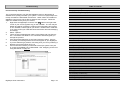
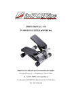
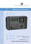
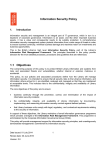
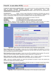
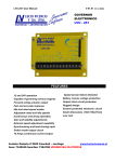
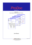
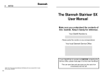
USER INSTRUCTIONS
LANGUAGE: ENGLISH
CONTENT OVERVIEW
> Driver’s Hours Rules Covered
> Digifobpro Functions
> Downloading Vehicle Unit data
> PC Software Installation
> Connecting to your PC
Mill House
44-46 Mill Green Road
Mitcham, Surrey
United Kingdom
Phone: +44 (0) 208 687 3900
Fax: +44 (0) 208 687 3919
E-mail: [email protected]
Copyright © Prosys Development Services 2008
> Data retrieval and Archiving
Manufacturer’s Warranty Information
Troubleshooting - Continued
This product comes with a 12 month manufacturer’s warranty. The warranty
will provide an automatic replacement of a product by return mail in the event
of a fault preventing the use of the product. Replacement will be made at no
cost to you.
Assigning a Com Port using Windows®
Provision of a replacement product is conditional upon the return of the complete faulty product.
Control Panel – System – Device Manager – Ports (Com and LPT) .
FTA will not replace the product if the fault:
•
•
•
•
•
•
•
•
•
Is caused by failure to follow the user’s instructions or neglect.
Is caused by deliberate or accidental damage.
Is caused by depleted rechargeable batteries.
Relates to failure to read a faulty or damaged driver card or Vehicle
Unit.
Relates to cosmetic damage that does not affect the correct output of
the device.
Relates to failure of peripherals and accessories (e.g. PC connector).
Relates to the failure to correctly install the packaged software on your
PC or laptop.
Cannot be found when inspected – in which case the product will be
returned to you.
FTA is not liable for any loss suffered as a result of not being able to
use the product, or consequential loss of any kind. FTA’s liability is
limited to the replacement cost of the product.
Technical Support
Operating systems vary slightly however you can generally find the Com Port
settings under the following Windows® menu headings;
Double click the ‘Ports (Com and LPT)’ entry in the list and this will list your
devices.
You should be able to identify one of the devices as being your ‘USB Serial
Port (Com #)’ .
RIGHT- CLICK the appropriate device and choose PROPERTIES. Select the
PORT SETTINGS tab at the top of the pop up window. Now click on the
ADVANCED settings button.
You should find a drop down box identifying the current port assigned to your
‘USB Serial Port’. You need to change this to an available port.
Once you have changed the port click OK – OK – and finally close the Device
Manager window and the Control Panel window. Repeat each of the steps in
‘PC Connectivity Troubleshooting’ on page 22
Digifobpro - complete reset
If your Digifobpro stops responding completely it is possible to reset the
device by holding down the Return button for 5 seconds. Do not use this
option as a regular feature especially if a firmware upgrade is in process as it
is equivalent to removing the power from the battery momentarily.
If a fault occurs, please check first that the rechargeable battery is not depleted. If the fault persists or you have any problems with using the device
please contact our Technical Helpline on 0871 474 4874 or e-mail [email protected].
Digifobpro User Instructions
Page - 23
Troubleshooting
Table of contents
Section One - Getting Started
Charging your Digifobpro and Digifobpro Controls
PC Connectivity Troubleshooting
4
Section Two - Using the Digifobpro
The connection between your PC and Digifobpro relies on their being an
available Com (serial) port within your system. This is not a physical port it is
merely set within the Windows® environment. Under certain circumstances
digifobpro Connect may not be able to obtain a free Com port. Follow the
steps to troubleshoot any Com port issues;
1.
Right Click the Digifobpro Connector icon
visible in the right lower
corner of your screen (system tray) on the Task Bar. The icon may be
hidden and will be revealed by clicking on the left pointing arrow head
on the Task Bar, bottom right of your screen. Please bear in mind that
if you have moved your Task Bar these instructions will need modifying
accordingly.
2.
Select ‘Options’.
3.
There are two troubleshooting options; Auto Detect and Test Connection. First select Auto Detect. The connection wizard will guide you
through the process.
4.
If the Auto Detect fails then try the Test Connection option. If this is
successful you should get the word ‘Found’ appear on your Digifobpro.
5.
If you are still having a problem connecting then you can try selecting a
different com port as shown in Fig 10.
6.
If this is still unsuccessful you will need to free up a system Com port
or choose an available port via Windows®. See ‘Assigning a Com Port
using Windows®’ on page 23.
Fig 10.
Driver Card - Quick View
5
Driver Card - Download
5
Driver Card - File Viewer
5
EU Driver’s Hours Rules covered by Digifobpro
6
Connecting to a Vehicle Unit
7
Vehicle Unit – Quick View
7
Vehicle Unit – Download
8
Information on TREPS
8
Setting Vehicle Unit Download Options
8
Speed Trace Navigation
10
Deleting files on your Digifobpro
11
Maintenance of your Digifobpro system
11
Setting the screen contrast
11
Turning off the Digifobpro
11
Section 3 - Using the Digifobpro Connect Software
Installing Digifobpro Connect Windows® software
12
Connecting the Digifobpro to your PC
13
Accessing the Functions Menu on Your PC
14
Viewing files on the Digifobpro with Digifobpro Connect
14
Management of Digifobpro files via your PC
Digifobpro User Instructions
Page - 22
14-17
View Archive Folder on PC
15
Digifobpro configuration via Digifobpro Connect Software
16
Digifobpro Connect Software Options
17
Upgrading your Digifobpro – Firmware updates
18
Tachograph Driver Card and Vehicle File Viewer
20-21
PC Connectivity Troubleshooting
22-23
Assigning a COM Port using Windows®
23
Resetting your Digifobpro
23
Digifobpro - Getting Started
Vehicle Unit data continued
Digifobpro Functions
Components
12.
13.
14.
15.
16.
17.
•
Digifobpro
•
Vehicle Unit Cable
•
USB Converter
•
USB Cable
Charging the device
18.
Digifobpro is supplied with a UK and Euro adapter. Select the appropriate
plug adapter for your region and insert it into the power unit.
Over Speeding Control Data: summary count of overspeeds
Overspeeding Event Data
Time Adjustment Data
Detailed Speed Data
Identification: details of the Vehicle Unit manufacture and software
Sensor Paired: details of the vehicle’s sensor unit paired with the Vehicle Unit
Calibration Data: summary of Vehicle Unit calibrations performed.
You may check at www.digifob.com for updates to the Tacho Viewer software.
Once the Power Adapter is plugged into the mains supply you can insert the
small single pin connector into the right hand side of the Digifobpro (see
‘Digifobpro controls’ below).
A red charging light is displayed in the unit when charging correctly. When
the unit is fully charged the charging light will change to green. Be aware that
the first charge may take several hours.
Battery life will be in excess of 20 hours in constant use (20mA consumption
with a 700 mAh battery rating) however the default power save features of
the Digifobpro will help to extend the battery life considerably in normal use.
Digifobpro controls
Return
Scroll
Menus
Enter or
ON
Vehicle
Connection
Power
Socket
Card
Digifobpro User Instructions
Page - 4
Digifobpro User Instructions
Page - 21
Tacho File Viewer
Together with your Digifobpro software we provide you with a free Tachograph File Viewer for use with Driver Card files and Vehicle Unit files. You
will find the Tacho File Viewer under your Windows® Start-ProgramsTachosys menu item.
This is a technical viewer and is not designed to provide analysis of Driver
Card or Vehicle Unit data. It is however ideal for spotting issues in either
Driver or Vehicle data. Simply browse to a Driver Card or Vehicle Unit file
and use the “File - Open” option on the top menu bar to open a file.
To turn Digifobpro ON, hold down the OK button for approximately 2 seconds.
To turn Digifobpro OFF scroll using the UP and DOWN arrows to the ‘Power
Off’ option listed in the units Main Menu, then press ok. Digifobpro will automatically switch itself off if no activity is detected for a number of minutes.
To install the software which will allow you to configure your Digifobpro to
download specific data from your VU, go to page 12 .
Driver Card data:
1.
2.
3.
4.
5.
6.
7.
8.
9.
10.
11.
12.
13.
14.
File Contents: lists every event within the Driver Card file
IC and ICC: Integrated circuit card identification information
Application Identification: low level card information
Identification: details of card holder
Card Download: last date of download
Driving Licence Info
Events Data: events relating to card insertion within the Vehicle Unit
Faults Data: list of faults relating to the interaction between the Driver
Card and the Vehicle Unit(s) into which the card has been inserted
Driver Activity Data: individual records of activity and time
Vehicles Used: a list of vehicles into which the Driver Card has been
inserted together with times and dates.
Places: Start and end places recorded by the Vehicle Unit onto the
Driver Card
Current Usage
Control Activity Data
Specific Conditions: manual entry information.
Vehicle Unit data:
1.
2.
3.
4.
5.
6.
7.
8.
9.
10.
File Contents: summary of the contents of the Vehicle Unit file
Vehicle Identification
Current Date Time
Downloadable Period
Inserted Card Type: the card type that was used to obtain the file
Download Activity Data
Company Locks Data: information on when a Company Card has been
used within the Vehicle Unit
Control Activity Data
Day Information: a summary of Driver Card insertion activity by day
Fault Data
Digifobpro User Instructions
Page - 20
Digifobpro User Instructions
Page - 5
Using the Digifobpro
Main Menu Options
Fig 9.
Main Menu - Driver Card: press the OK button whilst on this menu option.
Quick View: press the OK button whilst ‘Quick View’ is highlighted
and you will be prompted for a Driver Card. The Driver Card will now
be analysed against the latest EU rules. A filter screen allows you to
choose which elements of the analysis you wish to view (see
‘Filtering’ below). Scroll through the data using the UP and DOWN
arrows. Approximately one months worth of data is taken from the
card. The number of records to scroll through is indicated in the bottom right corner.
Download: press the OK button whilst the ‘Download’ option is highlighted and you will be prompted for a Driver Card. Digifobpro will
read the full contents of the card and commit it to it’s internal memory. At the same time Digifobpro produces an analysis of the Driver
Card against EU Driver’s hours rules. A filter screen allows you to
choose which elements of the analysis you wish to view (see
‘Filtering’ below). You can scroll through the analysis using the UP
and DOWN arrows. The analysis is stored within Digifobpro so you
can recall it at any time.
File Viewer: To view the analysis of Driver Card files stored on the
Digifobpro press the OK button whilst the ‘File Viewer’ option is highlighted. Scroll through the files stored using the UP and DOWN arrows. When you find the file you want press the OK button and the
file analysis will be read into the units memory. A filter screen allows
you to choose which elements of the analysis you wish to view (see
‘Filtering’ below).
Filtering: The data is split into categories; Information, Infringement, Summary and Latest . Turn options ON or OFF by using the
UP and DOWN arrows and turning an option ON or OFF with the OK
button. In the case of the Download and File Viewer options you
can specify a time period in weeks by highlighting the ‘Weeks’ option
and pressing OK, use the UP and DOWN arrows to increase or decrease the number of weeks and then press OK. Now highlight
SHOW and press OK. You can revise your option choices by pressing the RETURN button. Your option choices are saved for next
time.
If for some reason the firmware upgrade is unsuccessful it is possible to return to the previous firmware stored on the device. First turn the Digifobpro
OFF. With the unit now off, hold down the UP arrow and keep it held down,
now press the OK at the same time. Press OK when prompted to do so.
Digifobpro will now restore the former firmware. This option should only be
used as a last resort.
Main Menu - Vehicle Unit
You must use the cable provided to connect the Digifobpro to your Vehicle
Unit. The cable has the same connector at both ends and it does not matter
which end you place in the Digifobpro or the Vehicle Unit. Refer to your vehiDigifobpro User Instructions
Page - 6
Digifobpro User Instructions
Page - 19
Digifobpro Connect Windows® Software
You may change the Driver Card and Vehicle Unit file naming conventions to
suit your country or analysis software. Select the most appropriate option
from the drop down menu in Software Options (see Fig 8.).
Quick View: press the OK button whilst ‘Quick View’ is highlighted
and you will be presented with three options;
1)
2)
3)
Archive Settings:
1.
2.
Select the Archive tab at the top of the pop up window (see Fig 8.).
Choose whether you want ‘Automatic’ download of files from your Digifobpro or whether you wish to be notified of new files when the unit is
connected to your PC. By selecting Automatic each time your Digifobpro is connected to your PC any files that are not already on your PC
will be downloaded automatically. A small window at the bottom right
of your screen will indicate the progress when automatic transfer occurs.
4.
Choose the location in which you wish to store your Driver Card and
Vehicle Unit files when they are downloaded from Digifobpro.
5.
If you tick the ‘Place downloaded files into the sub-folder of the Driver
or Vehicle’ option, whenever Driver Card files or Vehicle Unit files are
downloaded from Digifobpro they will automatically be sorted into
separate directories by driver name or vehicle registration number.
6.
By ticking the ‘Include Driver Card Analysis file in Archive’ option you
will save the automatic analysis which the Digifobpro performs on each
Driver Card when it is uploaded to the unit. This could be useful for
subsequent analysis of the Driver Card.
By choosing the ‘Manual’ option you will have total control over what it is you
download from the Digifobpro. In this mode you will have to browse to the
Digifobpro and copy files manually using the supplied software
Digifobpro Connect - Upload Firmware File...
The Digifobpro unit holds information on the current EU drivers hours law.
Periodically laws may be changed or amended. This option allows you to
download the latest updates for your Digifobpro. It is also possible to change
the language of the device using a firmware upgrade file.
Select the ‘Upload Firmware File’ option and the Windows® explorer window
will open. Select the firmware upgrade file that you will have downloaded
from the Internet or been supplied by your retailer.
Events and Faults
Overspeeding
Speed Trace
Highlight an option by using the UP and DOWN arrows and press
OK. All of the available data from the Vehicle Unit is downloaded for
each of the three options. See ‘Speed Trace Navigation on page 8
for more information on how to use this feature.
The Events and Faults option has a filter screen which allows you to
choose which elements you wish to view. The filter options are as
follows;
General Events
VU Security
Sensor Security
Equipment Faults
Other Faults
Council Regulation (EC) No. 2135/98 and its Annex 1 (B) sets out
exactly which faults and events should be recorded by a Vehicle Unit.
You may wish to refer to Annex 1 (B) or your Tachograph user guide
for further information on Events and Faults.
You may include an option by highlighting it using the UP and DOWN
arrows and turning the option ON or OFF with the OK button, then
highlight SHOW and press OK. You can revise your selections by
pressing the RETURN button. Your option choices are saved for next
time.
Download: press the OK button whilst the ‘Download’ option is highlighted and you will be presented with three options; Latest, All and
Custom. The criteria for the Latest and All options is setup using the
supplied Digifobpro Connect software. You must first connect the
Digifobpro to your PC (see ‘Connecting the Digifobpro to your PC’
on page 13).
Once you select a file it will be automatically uploaded to the Digifobpro using
the steps shown in Fig 9. The firmware is actively installed and the Digifobpro restarted in connect mode.
Digifobpro User Instructions
Page - 18
Digifobpro User Instructions
Page - 7
Using the Digifobpro
The Custom option can be set up within Digifobpro Connect or on the
Digifobpro. On the Digifobpro scroll each TREP*( see page 10) using the UP and DOWN arrows and toggle each option ON/OFF using
the OK button. TREP 2 allows you to set the number of days required. Scroll to the TREP 2 option and press OK, you may now use
the UP and DOWN arrows to increase or decrease the number of
days, scroll one less than 000 to choose ALL days. Press OK to accept the setting. Finally scroll to the DOWNLOAD option and press
OK to download.
File Viewer: press the OK button whilst the ‘File Viewer’ option is
highlighted and you will have the option of scrolling through each of
the Vehicle Unit files by using the UP and DOWN arrows. You can
select a file by pressing the OK button this in turn gives you three
options;
1)
Events and Faults
2)
Over speeding
3)
Speed Trace
The Custom options can be set up within Digifobpro Connect or on the Digifobpro. On the Digifobpro scroll each TREP using the UP and DOWN arrows and toggle each option ON/OFF using the OK button. TREP 2 allows
you to set the number of days required. Scroll to the TREP 2 option and
press OK, you may now use the UP and DOWN arrows to increase or decrease the number of days, scroll one less than 000 to choose ALL days.
Press OK to accept the setting. Finally scroll to the DOWNLOAD option and
press OK to download.
Fig 7.
N.B. 255 Days
is equivalent to
ALL data.
Please note: File Viewer behaves exactly the same as the Quick
View function within this section except that it relates to the Vehicle
Unit file held on the Digifobpro and not on the Tachograph.
See ‘Speed Trace Navigation’ on below for more information on how
to use this feature.
Press the Return button the appropriate number of times to return to
the Main Menu.
Digifobpro Connect – Options...
This option allows you to define file locations , archive settings and download
preferences. It also gives you access to the Serial Port configuration to allow
connection between the PC and the Digifobpro (see ‘PC Connectivity Troubleshooting’ page 22).
Main Menu - Connect:
Fig 8.
Press the OK button whilst the ‘Connect’ option is highlighted. You
will receive a message ‘Awaiting Remote’. The Digifobpro is waiting
to connect to your PC (see Connecting the Digifobpro to your PC
on page 13).
Speed Trace Navigation
The Speed Trace is a chart which is displayed by the Main Menu - Vehicle
Unit - Quick View - Speed Trace option and the Main Menu - Vehicle Unit –
File Viewer option, provided that you have downloaded Trep 4 (Detailed
Speed).
The Speed Trace initially displays a chart showing speeds within a 24 hour
period represented by dots (see Fig 1.). At the top right of the Digifobpro
screen is displayed the highest speed in the period shown. Top centre of the
Digifobpro User Instructions
Page - 8
Digifobpro User Instructions
Page - 17
Digifobpro Connect Windows® Software
This option allows you to configure all attributes on the Digifobpro (see Fig
6.). Under ‘Device’ you can view the units; Version, Serial and Build Date.
Here you can also set your time zone by picking the most appropriate option
from the drop down list provided. If you have the optional printer available for
the Digifobpro you can enable it within the same window by ticking the
‘Enable digifobpro printer’ option.
Click on the appropriate option that is listed below ’VU Download’ (see Fig 7.
on page 17) to set your Trep download requirements (see ‘Information on
TREPS’ page 10) and number of days of activity you require for each of the
options; Latest, All and Custom. Click ‘Apply’ and the settings will be written
back to your Digifobpro ready for the next Vehicle Unit download.
Please note that by choosing 255 days it is the equivalent to asking for ALL
days as you will see on the selection screen.
The ‘Power Save’ option allows you to set how long the Digifobpro will remain on if it senses no activity.
Fig 6.
There are a number of navigation icons to the left of the screen. You may
scroll through these icons using the UP and Down arrows and select an icon
with the OK button.
Icon
Function within Speed Trace graph
Navigates to an earlier day which has speed data available.
Navigates to a later day which has speed data available.
Zooms out one step from the current view. Steps are; 24
hours, 8 Hours, Single Hours, Minutes, Seconds.
Zooms one step into the current view. Steps are; 24
hours, 8 Hours, Single Hours, Minutes, Seconds.
Shifts to the left effectively moving back in time for the day.
Shifts to the right effectively moving forward in time for the
day.
Fig 1.
Main Menu– Maintenance:
Delete file: when you select this option by highlighting it and pressing the OK button you will be able to use the UP and DOWN arrows
to scroll through the file contents on your Digifobpro. If you press OK
on any file you will receive the message ’Are you sure?’. If you click
OK the file will be permanently deleted from the unit. Click RETURN
to cancel the delete. You must use this option carefully.
Delete all: deletes all files from your Digifobpro. Use this option with
caution as if you have not downloaded files to your PC they will be
permanently lost. You will receive a warning message before deletion occurs. If you wish to proceed you must use the UP and DOWN
arrows to navigate to the OK option on screen and then press OK.
Digifobpro User Instructions
Page - 16
Digifobpro User Instructions
Page - 9
Using the Digifobpro
Select the CANCEL option on screen using the UP and Down arrows
and then press OK to cancel this action.
3.
Status: displays the amount of storage space used on the device
and the current battery status.
LCD Contrast: vary the screen contrast by using the UP and DOWN
arrows.
About: displays the software version number, language and serial
number of the Digifobpro.
Main Menu –Power Off:
4.
5.
6.
Power Off: highlight the ‘Power Off’ option by scrolling using the UP
and DOWN arrows. Press OK and your Digifobpro will turn off automatically. To turn the unit on hold the OK button for approximately 2
seconds.
Information on TREPS
Whenever you reference Unit file data on the Digifobpro we refer to the term
TREPS (transfer response parameters). A definition of each of the TREPS is
listed in the table below.
Download New: when a file is downloaded from the Digifobpro
it is updated on the Digifobpro with a status of ’Archived’ .
This feature allows the system to identify which files have
been downloaded (archived) and which have not. The
‘Download New’ feature will only be active when Automatic
Downloading is turned off.
Delete: allows you to highlight a file in the main window and
click ‘Delete’. This will permanently remove the file from the
Digifobpro. This option must be used with care as the file will
be deleted permanently.
Delete All: this option will permanently delete all files from the
Digifobpro. Clearly this option should be used with caution.
Properties: will show the properties of any highlighted file.
Here you can change the ‘Archive’ properties of a file. If you
deselect ‘Archived’ and ‘Archived Remotely’ next time you connect the Digifobpro to your PC this file will be automatically
downloaded provided that Archiving is set to Automatic (see
Digifobpro Connect – Options (page 17). This is particularly
useful when files have been lost on your PC or a download is
interrupted part way through.
If you right click a file in the file browser main window you will see three options; Download, Delete and Properties. These options are exactly as defined above.
Digifobpro Connect -View Archive Folder
TREP 1
Overview: includes data such as vehicle ID, Last VU
download and by which type of card.
TREP 2
Activities: all tachograph recordable actions performed in the use of the truck by a or other card
holder. Does not include faults.
TREP 3
Events and faults: all faults recorded on the tachograph including; overspeeds, power interruptions and
time adjustments.
TREP 4
Detailed speed: truck speed is recorded every second the truck is moving. There is a limit of 24 hours
of data.
TREP 5
Technical data: details relating to the vehicle unit
identity, software version and calibration.
Digifobpro User Instructions
Page - 10
This option within the Digifobpro Connect PC software allows you to navigate
quickly to the Driver Card and Vehicle Unit file archive directory on your PC.
Digifobpro User Instructions
Page - 15
Digifobpro Connect Windows® Software
Digifobpro Connect - Accessing the functions menu on your PC
To access all of the functions within your Digifobpro Connect PC software
Right Click the Digifobpro Connector
icon visible in the right lower corner
of your screen on the Task Bar. The icon may be hidden and will be revealed
by clicking on the left pointing arrow head on the Task Bar, bottom right of
your screen. Please bear in mind that if you have moved your Task Bar
these instructions will need modifying accordingly. The Digifobpro must be
connected to your PC and be in connection mode for the functions menu to
be activated (see ‘Connecting the Digifobpro to your PC’ on page 13).
Digifobpro Connect – View Files on Device: Digifobpro comes with its
own file browser software to enable you to manage the files that are held on
the Digifobpro via your PC. This is particularly useful for where you have
opted for Manual Download within the Archive Settings. Select the ‘View
Files on Device’ option and you will be presented with the file browser screen
as shown in Fig 5.
Fig 5.
Please note that any files that
have been archived from the
Digifobpro to the PC will have
an ‘A’ in the bottom left corner
when you view them on the
File Types: A summary of the quantity of files by type is shown in the
File Types section. You can click on ‘Driver Card’ or ‘Vehicle Unit’ to
restrict the file list to a particular type.
File Management:
1.
Upload: allows you to upload files from your PC’s hard drive to
the Digifobpro’s internal memory. Please bear in mind that the
Digifobpro is designed for the storage of Driver Card and Vehicle Unit files. It is not an appropriate medium for the mass
storage of other files.
2.
Download: you can highlight any file in the file window and
click ‘Download’. This will prompt you for a location and file
name in which to save the file.
Digifobpro User Instructions
Page - 14
EU Driver’s Hours Rules covered by Digifobpro
Digifobpro provides analysis of Driver Cards both in it’s Quick View and
Driver Card - Download The list below shows the information that can be
displayed on the Digifobpro in relation to drivers hours;
CATEGORY
DESCRIPTION
INFORMATION
LAST ACTIVITY
DISPLAYS WORK, DRIVE OR AVAILABLE AND THE DURATION. THE DATE/
TIME DISPLAYED REFERS TO WHEN THE ACTIVITY STARTED.
NEXT DAILY REST
ADVISES THE DATE/TIME THAT THE NEXT DAILY REST IS DUE BY TAKING INTO ACCOUNT ANY DAILY REST REDUCTIONS.
LATEST SHIFT
A SUMMARY OF THE LAST SHIFT SHOWING WORK, DRIVE AND AVAILABLE DURATIONS. A SHIFT IS DEFINED AS THE PERIOD FOLLOWING THE
LAST DAILY REST.
LATEST DAILY REST
SHOWS THE DURATION AND DATE AND TIME THE DAILY REST STARTED.
WEEKLY REST
DISPLAYS THE START DATE/TIME OF A CONTINUOUS PERIOD OF REST
GREATER THAN 24 HOURS AND LESS THAN 7 DAYS AND ITS DURATION.
SUMMARY W/C
WEEKLY SUMMARY; A SUMMARY OF WORK, DRIVE AND POA FOR A 1
WEEK PERIOD. DATE SHOWS THE WEEK START.
PERIOD OF INACTIVITY
A PERIOD OF INACTIVITY OF 7 OR MORE DAYS. THE DATE/TIME DISPLAYED REFERS TO THE START OF THE PERIOD.
INFRINGEMENTS
DRIVING BREAKS
INSUFFICIENT BREAK(S) TAKEN IN DRIVING OF 4HRS 30MINS OR MORE.
DATE/TIME REFERS TO THE START OF A PERIOD OF DRIVE WHICH
FOLLOWED A VALID BREAK OR DAILY REST.
INSUFFICIENT DAILY REST
THE DATE/TIME DISPLAYED REFERS TO THE START OF THE RELEVANT
SHIFT.
INSUFFICIENT DAILY REST DUE TO MORE
THAN 3 REDUCTIONS
DAILY REST HAS BEEN REDUCED MORE THAN 3 TIMES BETWEEN
WEEKLY RESTS. THE DATE/TIME DISPLAYED REFERS TO THE START OF
THE RELEVANT SHIFT.
DAILY DRIVE LIMIT
THE DAILY DRIVING LIMIT OF 9 HOURS (10 HOURS IF AN EXTENSION IS
AVAILABLE) HAS BEEN EXCEEDED. THE DURATION IS DISPLAYED.
DAILY DRIVE LIMIT EXCEEDED DUE TO MORE
THAN 2 EXTENSIONS
THE DAILY DRIVING LIMIT HAS BEEN EXTENDED TO 10 HOURS MORE
THAN 2 TIMES IN THE CURRENT CALENDAR WEEK. THE DATE/TIME
DISPLAYED REFERS TO THE START OF THE LAST SHIFT.
WEEKLY REST
INSUFFICIENT REST IN 6, 24 HOUR PERIODS FOLLOWING THE PREVIOUS WEEKLY REST. DATE/TIME SHOWS THE START OF THE 6 PERIODS.
WEEKLY DRIVING
MORE THAN 56 HOURS OF DRIVING HAS BEEN RECORDED IN A CALENDAR WEEK. DATE SHOWS THE WEEK START.
FORTNIGHTLY DRIVING
MORE THAN 90 HOURS OF DRIVING HAS BEEN RECORDED IN 2 CALENDAR WEEKS. DATE SHOWS THE FORTNIGHT START.
Digifobpro User Instructions
Page - 11
Digifobpro Connect Windows® Software
Connecting the Digifobpro to your PC
Digifobpro Connect Windows® Software
Minimum Recommended PC Specification
1.
Processor: Intel P4 1.4GHz, AMD Athlon 1.4 GHz
Memory: 512Mbytes
Hard disk: 40 Gbytes
Video Resolution: 1024 x 768
Operating Systems: Windows XP SP2 / Vista
Connect the cable with connector as shown in Fig 2, to the left side of
the Digifobpro. The other end of this cable can now be inserted into
the USB converter shown in Fig 3.
Fig 2.
In order to load the supplied software you must have a CD or DVD
Drive. In order to connect the Digifobpro to your PC you must have
an available USB connection.
2.
Connect the standard USB cable supplied, to a free USB socket on
your PC. The end of the USB cable as shown in Fig 4. should be connected to the available side of the USB converter shown in Fig 3.
Fig 4.
Installing the Digifobpro Connect Windows® Software
1.
2.
3.
4.
5.
6.
Fig 3.
Insert the CD provided into your optical disk drive. It will run automatically and a dialog box will appear. If the auto-run feature is disabled
on your system the program will fail to load automatically. Please
browse to the disk using Windows® Explorer and double-click
Setup.exe.
You will be prompted for your appropriate language. Please select
from the list and then click OK.
You will receive a welcome message, simply click ‘next’.
Choose the folder in which you wish the software program files to be
installed. The default folder is the standard location for Windows® programs. Click ‘next’.
Click ‘Install’ to begin the actual installation. This may take several
minutes.
Finally tick or untick the box labelled ‘Launch digifobpro Connect’ depending on whether you wish to start the program on completion of the
installation. Click ‘Finish’.
Please note that if you opted to launch Digifobpro Connect at the end of the
installation, an icon of a wheel with a cross in it will appear at the bottom right
of your screen (system tray).
3.
4.
5.
Ensure that the Digifobpro Connect software is started by selecting
Programs– Tachosys - digifobpro Connect to your PC.
Turn on your Digifobpro by pressing and holding the OK button for at
least 2 seconds.
By using the up or down arrow buttons on your Digifobpro, scroll to the
‘Connect’ option and press the OK button. Your Digifobpro should now
say ‘Connected’.
If your Digifobpro does not say ‘Connected’ then do the following;
1.
2.
3.
4.
Check all of the cabling and ensure the connections are secure.
Repeat step 3 above.
Repeat step 4 above.
Repeat step 5 above
If you are still having problems then disconnect the cabling from your PC and
try an alternative USB socket. If this still does not work then refer to ‘PC
Connectivity Troubleshooting’ on page 22
The cross denotes that the software is loaded and active however your Digifobpro is not connected. When you connect your Digifobpro the same icon
appears with a green tick to denote that the Digifobpro is successfully connected.
Digifobpro User Instructions
Page - 12
Digifobpro User Instructions
Page - 13