1
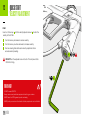
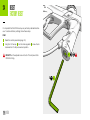
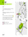
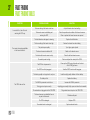
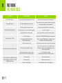
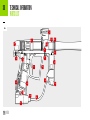
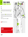
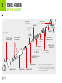
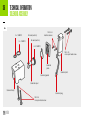
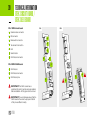
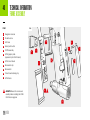
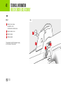
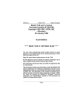
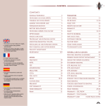
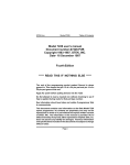
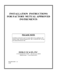
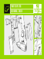
01
PLANET ECLIPSE: GTEK
USER MANUAL / ENGLISH
GTEK
.68 CAL
02
WARNINGS
READ CAREFULLY BEFORE USE
!
THE PLANET ECLIPSE GTEK IS NOT A TOY. PAINTBALL
SAFETY RULES MUST BE FOLLOWED AT ALL TIMES.
!
areless or improper use of the GTEK, including failure to follow
C
instructions and warnings within this User Manual could cause
serious injury or death.
!
Do not remove or deface any warnings attached to the GTEK.
!
aintball industry standard eye/face/ear and head protection
P
designed specifically to stop paintballs and meeting ASTM standard
F1776 (USA) or CE standard (Europe) must be worn by the user and
any person within range. Proper protection must be worn during
assembly, cleaning and maintenance.
!
Hearing protection should be worn.
!
Never shoot at a person who is not wearing proper protection.
!
ever look directly into the barrel of the marker. Accidental
N
discharge into the eyes may cause permanent injury or death.
Never look into the barrel or breech area of the GTEK whilst the
marker is switched on and able to fire.
!
Keep the GTEK switched off until ready to shoot.
!
Treat every marker as if it is loaded and ready to fire.
!
he electronic On/Off button is the marker’s disabling device, also
T
known as a safety. Always switch off the marker when not in use.
GTEK
!
Always fit a barrel-blocking device to the GTEK when not in use.
!
Always remove paintballs from the GTEK when not in use.
!
Do not field strip or remove any parts while the marker is
pressurised.
!
o not pressurise the GTEK without all the components of the
D
marker correctly installed, as high-pressure gas may be emitted.
!
Do not fire the GTEK without the bolt correctly installed.
!
Never put your finger or any foreign objects into the paintball feed
tube of the GTEK.
!
Never allow pressurised gas to come into contact with any part of
your body.
!
Always remove the first stage regulator and relieve all residual gas
pressure from the GTEK before disassembly.
!
Always remove the first stage regulator and relieve all residual gas
pressure from the GTEK for transport and storage.
!
Always follow guidelines given with your first stage regulator for safe
transportation and storage.
!
Always store the GTEK in a secure place.
!
Observe all local and national laws, regulations and guidelines.
03
WARNINGS
READ CAREFULLY BEFORE USE
!
Persons under 18 years of age must have adult supervision when
using or handling the GTEK.
!
Use only professional paintball fields where codes of safety are
strictly enforced.
!
se compressed air/nitrogen only. Do not use any other
U
compressed gas or pressurised liquid including CO2.
!
lways follow instructions, warnings and guidelines given with any
A
first stage regulator you use with the GTEK.
!
Use 0.68 inch calibre paintballs only.
!
Always measure your marker’s velocity before playing paintball,
using a suitable chronograph.
!
Never shoot at velocities in excess of 300 feet (91.44 metres) per
second, or at velocities greater than local or national laws allow.
!
Any installations, modifications or repairs should be carried out by
a qualified individual at a licensed and insured paintball facility.
WARNING!
This user manual must accompany the product in the event of resale or new
ownership. Should you be unsure at any stage you must seek expert advice.
GTEK
This Users Manual is in English.
It contains important safety guidelines and
instructions. Should you be unsure at any
stage, or unable to understand the contents
of this manual you must seek expert advice.
Le mode d’emploi est en Anglais.
Il contient des instructions et mesures de
sécurité importantes. En cas de doute, ou
s’il vous est impossible de comprendre le
contenu du monde d’emploi, demandez
conseil à un expert.
Este manual de usuarios (operarios)
Usarios está en Inglés.Contiene importantes
normas de seguridad e instrucciones. Si no
está seguro de algùn punto o no entiende los
contenidos de este manual debe consultar
con un experto.
Diese Bedienungs - und
Benutzeranleitung ist in Englisch.
Sie enthålt wichtige Sicherheitsrichtlinen und -
bestimmungen. Solten Sie sich in irgendeiner
WARNING
Weise unsicher sein, oder den Inhalte dies
Heftes nicht verstehen, lassen Sie sich bitte
von einen Experten beraten.
CONTENTS
GAME ON!
04
QUICK START (06-16)
RESET (24-25)
06
08
09
10
11
12
13
14
16
24Factory reset
25
Installing a 9V battery
Setting up the GTEK
Switching the GTEK On/Off
LED indicators
Switch the GTEK On/Off with the OLED board fitted
OLED indicators
Velocity adjustment
Trigger adjustment
Unloading the GTEK
Storage and transportation
MAINTENANCE
17
On-line maintenance videos
ELECTRONICS (18-23)
18The set-up mode
19
LED parameters
20The OLED set-up mode
21
OLED parameters
FAULT FINDING (26-29)
26
Fault finding tables
TECHNICAL INFORMATION (30-41)
30
Parts list
32
Tournament lock
33
Installing the GTEK OLED board
34
SL4 inline regulator
35
GTEK bolt assembly
36
Solenoid assembly
37
On/Off Purge System (OOPS) assembly
38
Trigger assembly
Clamping feed tube assembly
39GTEK circuit board
GTEK OLED board
40
Frame assembly
41
Breech Sensor (BS) assembly
SUPPORT (42-45)
42Index
43
Our promise
44Notes
GTEK
05
GTEK
QUICK START
SETTING UP THE GTEK
06
FIG-1
HEX
I
5/32
H
J
6
E
1
A
L
B
K
GTEK
G
F
5
4
2
D
C
3
3
QUICK START
SETTING UP THE GTEK
07
FIG-1
A
Ensure the marker is switched off before you begin.
B
Check the condition of the macroline before you progress.
C
Screw both ends of the barrel together.
Screw the barrel tip counter-clockwise into the barrel back.
D
Screw the complete barrel to the marker.
The barrel back screws clockwise into the marker body.
E
Fit a barrel blocking device for safety.
F
nsure the marker is de-gassed.
E
Unscrew the On/Off Purge System (OOPS) knob counter-clockwise.
G
Attach the pre-set air system.
Screw the air system clockwise into the OOPS body.
H
Loosen the clamping feed neck.
Open the feed neck lever away from the feed neck.
Unscrew the feed neck lever screw counter-clockwise.
I
Attach the loader.
If the feed neck is too tight, loosen the clamping feed neck more.
J
Secure the loader.
Close the feed neck lever to secure.
Screw the feed neck lever screw clockwise to tighten.
K
as the marker.
G
Screw the On/Off Purge System (OOPS) knob clockwise.
L
Switch on the GTEK.
GTEK
1
IMPORTANT! To switch On/Off, see pages 8-11.
2
IMPORTANT! Damaged or worn macroline can be dangerous.
3
DO NOT over-tighten the barrel.
4
IMPORTANT! Always ensure marker is de-gassed when setting up.
5
NEVER use CO2. Compressed air or Nitrogen only.
6
DO NOT over-tighten the feed neck. This may damage the GTEK.
WARNING!
Always make sure the marker is off with a barrel blocking device installed and
that no paintballs are in the GTEK or loader before installing an air system.
Compressed air and nitrogen systems can be extremely dangerous if handled
or used incorrectly.
Only attach an air system certified for use within the country of use.
Never add lubricants or grease into the fill adaptor of the air system regulator.
Ensure that all screws are tightened and no parts are loose before installing an
air system.
Do not pressurise the GTEK without the bolt system correctly installed, as high
pressure gas will be emitted.
Do not install a compressed air system or load paintballs into the GTEK until
you feel confident with your ability to handle the marker safely and responsibly.
WA
QUICK START
SWITCHING THE GTEK ON/OFF
08
FIG-1
C
The navigation console A houses the Select button B and the LED
indicator C . Use the console to switch the GTEK On/Off and change
the marker settings.
B
FIG-1
To switch the GTEK on press and hold the Select button. Release
the Select button when the LED lights up and the GTEK will begin
its power up sequence. At the end of the power up sequence the
LED Indicator will show the battery status with a steady colour for 2
seconds (see table 1 for battery status colour information). 1,2
TABLE 1
LED COLOUR
BATTERY STATUS
GREEN
Battery level is good.
YELLOW
Battery level is low.
RED
Replace the battery.
To switch the GTEK off press and hold the Select button. Release the
Select button when the LED on the navigation console turns red. The
GTEK will now switch off.
1
When the GTEK is turned on, the breech sensor is automatically enabled.
2The LED colours displayed during the power up sequence may vary depending on
where the marker was originally purchased.
GTEK
A
QUICK START
LED INDICATORS
09
FIG-1
A
B
FIG-1
After displaying the battery status on power up the GTEK’s LED indicator
A will display the status of the breech sensor (BS). The breech sensor
(BS) is used to detect paintballs in the breech of the marker.
The LED also indicates the various marker parameter settings.
Table 2 shows each LED colour and its relevant BS status.
See pages 18-19 for marker parameter indicators.
Battery status check
1
Tap the Select button B .
2
The LED indicator A will turn a steady colour for 2 seconds
(see table 1 on page 08 for battery status colour information).
Firing the GTEK
Pull the trigger to fire the GTEK. If the marker is able to fire then it will
do so.
WARNING!
When the battery indicator is being displayed the marker is still on and will
fire if the trigger is pulled - depending on the BS status.
Do not dry fire/shoot the marker without paintballs. Prolonged dry firing may
lead to damage/wear of the internal components of the marker.
GTEK
TABLE 2
LED COLOUR
BREECH SENSOR (BS) STATUS
FLASHING YELLOW
BS enabled. NO paintball detected.
Marker WILL NOT fire.
WARNING
FLASHING LIGHT BLUE
BS enabled. Paintball detected.
Marker WILL fire.
FLASHING PURPLE (SLOW)
BS disabled. Marker WILL fire.
FLASHING PURPLE (FAST)
Blockage detected. BS disabled.
Marker WILL fire.
QUICK START
SWITCHING THE GTEK ON/OFF
WITH THE OLED BOARD FITTED
10
FIG-1
C
B
The navigation console A houses the Select button B the LED
indicator C and the OLED display D . Use the console to switch the
GTEK On/Off and change the marker settings.
The LED indicators are still functional, regardless of the installation of
the OLED board.
A
FIG-1
Switching on the GTEK
Press and hold the Select button. Release the Select button when the
LED lights up and your GTEK will begin its power up sequence.1,2
D
Firing the GTEK
Pull the trigger to fire the GTEK. If the marker is able to fire then it will
do so.
Switching off the GTEK
Press and hold the Select button until the display shows GOODBYE.
Release the Select button.
1
When the GTEK is turned on, the breech sensor is automatically enabled.
2The LED colours displayed during the power up sequence may vary depending on
where the marker was originally purchased.
GTEK
WARNING!
Do not dry fire/shoot the marker without paintballs. Prolonged dry firing may
lead to damage/wear of the internal components of the marker.
WARN
QUICK START
OLED INDICATORS
11
FIG-1
C
FIG-1
A
D
The breech sensor (BS) indicator A shows the following information:
E
BS Enabled and ball detected
The GTEK can be fired at the chosen firing mode.
BS Enabled no ball detected
The GTEK cannot be fired.
F
B
BS Disabled
The GTEK can be fired as per the BS OFF ROF (see page 21).
BS Fault detected
System is disabled. The GTEK can only be fired at a maximum
rate of 2 bps less than the maximum rate of fire and 10 bps max.
The battery level indicator B shows the following information:
The lock indicator C shows the following information:
Full battery
The battery is fully charged.
Locked
Set-up mode cannot be accessed.
This is the tournament legal state.
Drained battery
Battery is at approximately 30% of useful charge.
Unlocked
Set-up mode can be accessed.
Battery circuit fault
The battery level cannot be determined.
For more information about the shot counter D and firing mode
E and F see pages 21 to 23.
GTEK
To change the tournament lock state see page 32.
WARNING!
When the battery indicator is being displayed the marker is still on and will
fire if the trigger is pulled - depending on the BS status.
WA
QUICK START
VELOCITY ADJUSTMENT
12
FIG-1
FIG-1
Insert a 1/8 hex key A into the velocity adjuster screw B to alter the
velocity of the GTEK.
1
Turn the hex key clockwise to reduce velocity.
2
Turn the hex key counter-clockwise to increase velocity.
3
Fire two clearing shots after each velocity adjustment for an
accurate velocity reading.
B
DO NOT turn the adjuster screw in too far. This will prevent the
GTEK from firing.
HEX
1
WARNING!
DO NOT exceed 300FPS.
Always wear correct protective equipment when firing your marker.
NEVER leave the GTEK gassed up when unloading.
NEVER point your marker in the direction of other people when not on the field.
GTEK
1/8
A
WARNING
+
–
1
QUICK START
TRIGGER ADJUSTMENT
13
FIG-1
FIG-1
The pre-travel screw A adjusts the distance the trigger travels before
the microswitch is actuated. Clockwise reduces the amount of travel
(shortening the trigger), counter-clockwise increases the trigger pull
distance.
HEX
The trigger pin locking screw B locks the trigger pin in place.
Clockwise locks the pin, counter-clockwise releases the pin.
1/16
+
The trigger spring screw C adjusts the spring strength of the trigger
return. Clockwise increases the spring strength, counter-clockwise
reduces the spring strength.
The post-travel screw D adjusts the distance the trigger travels once
the microswitch has been actuated. Clockwise reduces the amount of
travel (shortening the trigger), counter-clockwise increases the trigger
pull distance.
WARNING!
Always make sure the marker is OFF and de-gassed with a barrel blocking
device installed and that no paintballs are in the GTEK or loader before
adjusting the trigger
Do not wind the screws in too far as this may prevent the GTEK from firing
or even damage the marker.
If the pre-travel screw is wound in too far this could cause the GTEK to fire
unintentionally.
GTEK
WARNING
–
–
+
A
B
C
–
+
D
+
–
QUICK START
UNLOADING THE GTEK
14
FIG-1
5
HEX
F
5/32
1
E
B
G
GTEK
6
A
2
H
D
C
4
3
QUICK START
UNLOADING THE GTEK
15
FIG-1
A
Switch the marker off.
B
Ensure that a barrel blocking device is fitted for safety.
C
e-gas the marker.
D
Unscrew the On/Off Purge System (OOPS) knob counter-clockwise.
D
Remove the pre-set air system.
Unscrew the air system counter-clockwise from the OOPS body.
E
Loosen the clamping feed neck.
Open the feed neck lever away from the feed neck.
Unscrew the feed neck lever screw counter-clockwise.
F
emove the loader.
R
If the feed neck is too tight, loosen the clamping feed neck more.
G
Remove the barrel from the marker body.
Unscrew counter-clockwise to remove.
H
emove the barrel tip from barrel back.
R
Unscrew clockwise to remove.
1
IMPORTANT! Extra precaution to avoid injury.
2
IMPORTANT! To switch off/on, see pages 8-11.
3
IMPORTANT! Always de-gas before unloading.
4
IMPORTANT! Always remove air system before unloading.
5
IMPORTANT! Always remove any paintballs from the breech of the
marker once the loader has been removed.
6
IMPORTANT! Unscrew the barrel tip CLOCKWISE from the back.
WARNING!
Always make sure the marker is off with a barrel blocking device installed and
that no paintballs are in the GTEK or loader before unloading.
Compressed air and nitrogen systems can be extremely dangerous if handled
or used incorrectly.
NEVER leave the GTEK gassed up when unloading.
NEVER point your marker in the direction of other people when not on the field.
Remove any paintballs from the breech before storing your GTEK.
GTEK
WA
QUICK START
STORAGE AND TRANSPORTATION
16
1
Your GTEK must be clear of all paint and propellant during
transportation or storage.
2
Make sure the GTEK marker is switched off.
3
Remove the barrel from the marker.
4
Make sure the marker is clean of any paint residue, dirt and
moisture.
5
Store your GTEK in a clean, cool, dry place.
6
Keep your GTEK away from any unauthorized and unsafe users.
7
Remove the battery when storing your GTEK to prevent
unauthorized use.
WARNING!
8
Protect your GTEK from excessive heat during transportation.
9
hen transporting a paintball marker by air, check with the airline
W
regarding their policies on transporting paintball equipment as hold
luggage before arriving at the airport.
10
Observe and obey all local and national laws concerning the
transportation of paintball markers.
11
Use the box in which the marker was originally supplied to protect
the marker against rough handling during transport.
Never carry your GTEK un-cased when not on a playing field. The non-playing public and law enforcement personnel may not be able to distinguish between a paintball
marker and a real firearm. For your own safety and to protect the image of paintball, always carry the Eclipse GTEK (or any other paintball marker) in a suitable marker
case such as the one in which it was supplied.
GTEK
WARN
MAINTENANCE
ON-LINE MAINTENANCE VIDEOS
17
To help demonstrate how to maintain and service essential parts
of the GTEK we’ve created a collection of dedicated marker
maintenance videos to guide the user through each step.
From basic, to more advanced parts of the GTEK, we’ve got
your back.
Visit our Tech Room YouTube channel and check out the GTEK
Maintenance playlist.
www.youtube.com/user/planeteclipsetv
GTEK
ELECTRONICS
THE SET-UP MODE
18
To modify the GTEK parameters you must enter the set-up mode:
Modifying a parameter:
1
Switch the tournament lock off (page 32).
1
Enter the set-up mode.
2
Fully depress the trigger.
2
Select a parameter.
3
Switch on the GTEK (with trigger depressed).
3
Push and hold Select button for 1 second to confirm.
4
Release the trigger.
4
The LED will go off.
5
If the LED flashes red, the tournament lock is still on.
5
Increase the unit value using the trigger, one pull per unit.
Do not pull the trigger if the value should be 0.1
6
Push the Select button to switch to tenths values.2
7
Increase the tenths value using the trigger, one pull per tenth.
Do not pull the trigger if the value should be 0.
8
Push the Select button to confirm. The LED will flash 3 times.
The LED will show green if the changes are confirmed.
The LED will show red if the changes are NOT confirmed.
If the LED is red repeat 5
9
ush and hold the Select button until the LED turns blue to exit
P
set-up mode.
Once in the set-up mode, use the trigger to cycle through the
parameters, indicated by LED colours (see table below). Quickly press
the Select button on any parameter to display the current settings.
LED COLOUR
PARAMETER
RANGE
RED
Pre-set
1 to 4
GREEN
Maximum ROF with BS on
(capped modes only)
4.0 to 15.0 bps
BLUE
Maximum ROF with BS off
4.0 to 15.0 bps
PURPLE
Dwell
8.0 ms to 16.0 ms
LIGHT BLUE
Debounce
1 to 10
A long LED flash indicates the unit, whilst a short LED flash indicates the
tenth. Eg, 5 long flashes and 3 short flashes would indicate 5.3.
GTEK
1The settings will return to their previous saved values if you do not
pull the trigger for 5 seconds.
2 If a parameter does not support tenths, this will be skipped.
ELECTRONICS
LED PARAMETERS
19
The LED indicator communicates with the user through colour.
This overview page explains each colour and their roles once you enter the set-up mode (see page 18).
LED COLOUR
PARAMETER
DESCRIPTION
1 of 4 pre-set firing modes that comply with global paintball regulations.
Modes may vary depending on global location and GTEK model.
1 Uncapped Semi.
One shot per trigger pull with no max bps limit.
RED
Preset
2 Capped Semi.
One shot per trigger pull - 15 bps max.
3 PSP 10.2.
PSP style ramping with 0.8 ms delay - 10.2 bps max.
4MILL 10.2.
Millennium Series style ramping kicks in after 3 consecutive trigger pulls - 10.2 bps max.
GREEN
Maximum ROF (BS ON)
This controls how fast the GTEK can fire with the breech sensor on. Capped modes only.
BLUE
Maximum ROF (BS OFF)
This controls how fast the GTEK can fire with the breech sensor off. This should be set to the slowest speed
of the loader.
PURPLE
Dwell
LIGHT BLUE
DeBounce
FLASHING BLUE
Factory reset
GTEK
This controls the amount of time that the solenoid is energised, dictating the amount of gas released with
each shot.
This controls the amount of ‘anti-trigger bounce’ that is present.
Press and hold the tournament lock button (page 32) for 2 seconds to restore all settings back to factory
standard. the LED will flash blue to confirm this has been successful.
ELECTRONICS
THE OLED SET-UP MODE
20
To modify the parameters you must enter the
set-up mode:
1
Switch the tournament lock off (page 32).
2
Fully depress the trigger.
3
Switch on the GTEK (with trigger depressed).
4
Release the trigger.
5
If the LED flashes red, the tournament lock is
still on.
6
Once in the set-up mode, the OLED will display
SETUP.
7
Use the trigger to cycle through the parameters,
indicated by the screens opposite.
8
Quickly press the Select button on any
parameter to display the current settings.
See pages 21-23 for parameter descriptions.
GTEK
ELECTRONICS
OLED PARAMETERS
21
PRESET
1 of 4 pre-set firing modes that comply with global paintball regulations.
Modes may vary depending on global location and GTEK model.
1 Uncapped Semi.
One shot per trigger pull with no max bps limit.
2 Capped Semi.
One shot per trigger pull - 15 bps max.
3 PSP 10.2.
PSP style ramping
4MILL 10.2.
Millennium Series style ramping
BS ON ROF
BS OFF ROF
This controls how fast the GTEK can fire with the
breech sensor on. Capped modes only.
This controls how fast the GTEK can fire with
the breech sensor off. This should be set to the
slowest speed of the loader.
Available range: 4.0 - 15.0 bps
Default setting: 15.0 bps
GTEK
Available range: 4.0 - 15.0 bps
Default setting: 10.0 bps
ELECTRONICS
OLED PARAMETERS
22
KICK IN
DWELL
The trigger pulls per second (pps) before ramping
can start.
Solenoid energise time in milliseconds (ms) for
each shot.
Available range: 5.0 - 10.0 pps
Available range: 18.0 - 28.0 ms
Default setting: 5.0 pps
Default setting: 23.0 ms
RESTART
DEBOUNCE
The time in seconds (s) after the last trigger pull
before ramping is cancelled.
Trigger anti-bounce settings.
(1 = lowest level of filtering / 10 = highest level).
Available range: 0.0 - 1.0 s
Available range: 1 - 10
Default setting: 0.0 s
GTEK
Default setting: 5
ELECTRONICS
OLED PARAMETERS
23
SLEEP
DISPLAY
Auto power-off time in minutes (min).
Sets the display information for the run screen.
Available range: 0 - 60 min
SHOTS: Displays the shot counter
Default setting: 20 min
ROF: Displays the ROF indicator
ZERO
Allows the user to reset the counters and indicators to ZERO.
NONE: Don’t zero anything
SHOTS: Zero the shot counter
ROF: Zero the ROF indicator
BOTH: Zero shot counter and the ROF indicator
GTEK
RESET
FACTORY RESET
24
FIG-1
It is important that the GTEK is set-up as per factory standards before
use. To restore to factory settings, follow these steps.
FIG-1
Reset the control parameters (page 19)
2
Using the 1/8 hex key A turn the inline regulator B screw 4 turns
clockwise from it’s fully screwed-out position.
1
DO NOT turn the adjuster screw in too far. This will prevent the
GTEK from firing.
B
HEX
1
GTEK
1/8
A
+
–
1
FIG-1
A
Switch off the GTEK and place on a flat surface - feed neck facing
away from you and the barrel pointing to the right.
FIG-1
Using the 5/64” (2mm) hex key A remove the grip screws on the right
hand side of the grip.
1
FIG-2
A
Gently remove the 9V battery using the recessed access point B .
Install a new 9V Alkaline battery (type PP3, 6LR61, 1604A) with the
battery connectors C facing downwards inside the frame.
Replace the rubber grips and tighten the screws as in FIG-1.
1
DO NOT over-tighten the screws.
2
DO NOT use re-chargeable or poor quality batteries.
FIG-2
2
C
B
GTEK
5/64
HEX
RESET
INSTALLING A 9V BATTERY
25
FAULT FINDING
FAULT FINDING TABLES
26
SYMPTOM
Although a fresh battery has been fitted,
the GTEK will not switch on.
The battery does not seem to last very long.
The GTEK leaks from the solenoid
and/or manifold.
POSSIBLE CAUSE
SOLUTION
The battery has drained on the shelf.
Replace with another battery.
The battery connector is not making
proper contact with the battery.
Disconnect the battery. Gently squeeze the large terminal
on the battery connector to reduce its diameter.
Reconnect the battery.
The battery type is of a low quality.
Use an alkaline or lithium battery.
Do not use a low quality or rechargeable battery.
The two o-rings under the solenoid body or the gasket
under the solenoid plate are damaged or dirty.
Ensure the gasket is seated correctly.
Replace the gasket if damaged using GTEK parts kit.
Check condition of the 5x1 NBR70 and 3x1 NBR70 o-rings
under the solenoid body.
Solenoid valve and/or manifold are over-pressurised.
Check the output pressure of the inline regulator
and adjust accordingly.
Clean and inspect the inline regulator assembly paying
particular attention to the piston tip and regulator seal.
Replace damaged components as necessary.
Damaged or incorrect seals on the solenoid spool.
Replace and/or lubricate solenoid spool seals.
Damaged GTEK SMC solenoid pilot valve.
Replace GTEK SMC pilot solenoid valve.
Dirty or damaged can o-rings.
Clean and lubricate or replace 020 NBR70 and
017 NBR o-rings on the front of the can.
Dirty or damaged o-rings on the spool.
Clean and lubricate or replace the 011 NBR70 and
012 NBR70 o-rings on the main spool.
Dirty or damaged bolt o-rings.
Clean and lubricate or replace 14x2 NBR70 o-ring
on the back of the bolt.
Dirty or damaged rear bolt guide o-ring.
Clean and lubricate or replace 016 NBR70 o-ring
on the back of the bolt guide.
The GTEK leaks down the barrel.
GTEK
FAULT FINDING
FAULT FINDING TABLES
27
SYMPTOM
Low rate of fire / rate of fire not
reaching the ROF cap.
The marker is breaking paintballs
in the barrel or breech.
The GTEK does not fire.
GTEK
POSSIBLE CAUSE
SOLUTION
The force setting of the loader is too low.
Adjust the loader force feed setting.
The breech sensor is defaulting and
reducing the ROF.
Check the position and condition of the breech sensors.
Clean or replace the breech sensors as required.
The ball detents are damaged or missing.
Replace the ball detents.
The force setting of the loader is too high.
Reduce the loader force feed setting.
The paint is poor quality.
Try a higher grade of paint.
The breech sensor is switched off.
Switch on the breech sensor.
The bolt and/or breech sensor is dirty
Clean the bolt and breech sensor.
The velocity is set too high.
Check and adjust the velocity of the GTEK.
The GTEK is not powered on.
Power up the GTEK using the button on the back
of the GTEK grip frame.
The OOPS is not fully engaged.
Twist the OOPS knob in until it engages.
The battery quality or charge level is very low.
Install new high quality alkaline or lithium battery.
The battery is flat.
Replace the battery.
The DWELL parameter is set too low.
Increase the DWELL parameter.
The trigger is set-up incorrectly.
Adjust trigger correctly to fully open and close the microswitch.
The solenoid is not plugged into the GTEK PCB.
Plug solenoid wire into port on the GTEK PCB.
The breech sensor is enabled but there is
no paint in the breech.
Fill loader with paint.
The PCB is damaged.
Replace PCB.
The solenoid valve is damaged.
Replace solenoid valve.
FAULT FINDING
FAULT FINDING TABLES
28
SYMPTOM
POSSIBLE CAUSE
SOLUTION
Low constant velocity.
The inline regulator output pressure set too low.
Increase the output pressure of the inline regulator.
High velocity first shot.
The inline regulator pressure is creeping.
Strip and clean the inline regulator replacing the regulator
seal inside the regulator adjuster assembly.
The battery quality or charge level is low.
Install a new high quality alkaline or lithium battery.
Velocity drop-off during rapid fire.
The trigger is very “bouncy”.
The breech sensor is not reading correctly.
The breech sensor turns itself off after firing
and the display shows that there is a fault
with the breech sensor.
GTEK
Air system regulator does not have high enough flow.
Try another air system.
Dirty/partially blocked inline regulator.
Strip, clean, lubricate and rebuild the inline regulator.
Incorrect filter settings.
Check that your DEBOUNCE settings suit your trigger set-up.
The trigger pull is too short and the
return strength is too low.
Refer to using the GTEK section for guidelines of how
to adjust your GTEK trigger accordingly.
The breech sensor is dirty.
Keep the breech sensor clean to ensure correct readings.
The breech sensor is fitted incorrectly.
Check that the red receiver is on the right-hand side
of the breech and the sensors pointing towards each
other through the breech.
There is a broken wire or contact or a short
circuit on either of the breech sensor cables.
Check the plug of the cables.
Check for cuts or pinches in the sensor cables.
The sensor is dirty.
Clean the breech sensor.
The sensor is faulty.
Replace the breech sensor.
The sensor is out of place.
Re-install breech sensor. Check alignment.
FAULT FINDING
FAULT FINDING TABLES
29
SYMPTOM
POSSIBLE CAUSE
SOLUTION
Two or more balls are being
fed into the breech.
Worn, damaged or missing ball detents.
Change the rubber ball detent.
GTEK is inconsistent.
GTEK is inefficient.
When the GTEK powers up the LED
flashes white or red.
The feed force too high from loader.
Adjust loader settings/use lower force loader.
The inline regulator is supercharging.
Strip and clean inline regulator, replace regulator seal.
The DWELL is too low.
Increase the DWELL setting.
Poor quality paintballs.
Use better quality paintballs.
Poor paintball size to barrel bore match.
Use a closer paintball to barrel bore size.
Inconsistent air supply from air system.
Use a good quality air system.
Poor paintball size to barrel bore match
Use a closer paintball to barrel bore size.
The trigger is being pulled.
Release the trigger before powering on the GTEK.
Microswitch is permanently depressed by an
incorrectly set trigger.
Adjust the trigger so that when the trigger is at
rest the microswitch is not being activated.
If an issue with the GTEK cannot be solved using the fault finding guide,
contact your nearest Eclipse Service Centre for assistance.
GTEK
TECHNICAL INFORMATION
PARTS LIST
30
FIG-1
1
2
4
3
21
5
6
8
12
9
7
13
11
10
19
15
16
14
17
19
18
GTEK
20
TECHNICAL INFORMATION
PARTS LIST
31
FIG-1
1
Clamping feed tube assembly
12
Body plug
2
Marker body
13
SL4 inline regulator assembly
3
Quick-release bonnet
14
Regulator sleeve
4
Bolt assembly
15
Navigation console
5
Rubber detent
16
9V battery
6
Breech sensor (BS) unit
17
On/Off Purge System (OOPS) retaining nut
7
Solenoid assembly
18
OOPS assembly
8
Rear frame screw
19
Macroline fitting
9
Front frame screw
20
Macroline
10
Frame assembly
21
Barrel o-ring #016 NBR70
11
Trigger assembly
GTEK
TECHNICAL INFORMATION
TOURNAMENT LOCK BUTTON
32
FIG-1
A
B
1
5/64
HEX
FIG-1
To access the tournament lock button use the 5/64” (2mm) hex key
A remove the grip screws on the left hand side of the grip B .
FIG-2
The tournament lock button C is on the left side of the circuit board
(see page 39). To lock / unlock your marker push the button once.
B
The LED or OLED will display the locked/unlocked mode status (see
pages 18-23).
Replace rubber grip and screws as per Fig-2.
1
FIG-2
DO NOT over-tighten the screws.
C
WARNING!
Always ensure the marker is made safe before changing the tournament lock
state to avoid accidentally firing the marker.
GTEK
WARNING
FIG-1
A
5/64
HEX
TECHNICAL INFORMATION
INSTALLING THE GTEK OLED BOARD
33
B
1
FIG-1
Using the 5/64” (2mm) hex key A remove the grip screws B on both
sides of the grip. Remove the grips and the battery (see page 25).
FIG-2
FIG-2
FIG-3
C
Gently unplug the BS, solenoid and microswitch connectors C
(page 39) and gently remove the GTEK graphic plate D (page 40).
D
FIG-3
E
Push from the right/underside to remove GTEK circuit board E .
FIG-4
Attach the GTEK OLED board F to the GTEK circuit board G mating
the OLED board pins to the OLED connector H (page 39).
FIG-4
FIG-5
J
G
FIG-5
Insert the circuit board and OLED board into the frame space I .
Ensure the board is held in place by the retaining clip J (page 40).
Reverse Fig-2 and Fig-1 to complete installation.
1
DO NOT over-tighten the screws.
2
IMPORTANT! Ensure that the pushbutton cap does not damage
the red pushbutton on the circuit board. Point the marker
towards the ceiling so that the pushbutton cap falls away from
the circuit board.
GTEK
I
H
F
2
TECHNICAL INFORMATION
SL4 INLINE REGULATOR
34
1,2
FIG-1
Adjuster o-ring
#011 NBR70
Adjuster top
FRM o-ring
18 x 2 NBR70
Body plug
Purge poppet
spring 4
Regular bottom
1/8 NPTF straight
macroline fitting
Swivel o-rings
#015 NBR70
Body filter
Purge
poppet 4
Regulator
piston
Regulator spring 3
Adjuster external o-ring
#011 NBR70
10-32 UNF x 3/8”
socket button head
Body plug o-ring
#006 NBR70
Piston o-ring
14 x 2 NBR70
Adjuster internal o-ring
#008 NBR70
Regulator seal
Regulator swivel
GTEK
Regulator body
Adjuster bottom
1
Reset the SL4 regulator to factory after re-assembly.
2
only use the SL4 regulator with the GTEK.
3
only use the GTEK SL4 spring with the SL4 inline regulator.
4Failure to re-install the purge poppet assembly correctly
could seriously damage the GTEK.
TECHNICAL INFORMATION
GTEK BOLT ASSEMBLY
35
FIG-1
14 x 2 NBR70
Quick-release bonnet
Valve chamber
#010 NBR70
#020 NBR70
Bolt guide
#012 NBR70
#011 NBR70
Switch
#020 NBR70
14 x 2 NBR70
#012 NBR70
#015 NBR70
#015 NBR90
#020 NBR70
Internal:
#017 NBR70
#013 NBR70
#015 NBR70
#013 NBR70
#020 NBR70
#013 NBR70
#008 NBR70
Spool
Spool spring
Spring guide
Bolt pin
GTEK
Plunger
Can
#013 NBR70
Bolt
TECHNICAL INFORMATION
SOLENOID ASSEMBLY
36
FIG-1
3 x 1 NBR70
5 x 1 NBR70
#6 seal (custom)
M1.6 x 5
machine screws
#6 seal (custom)
6 x 1 NBR70
M2 x 16
cross pan-head screw
Solenoid
plate
Solenoid gasket
Solenoid pilot
Solenoid spool
Solenoid body
Solenoid plug
M2 x 16
cross pan-head screw
GTEK
TECHNICAL INFORMATION
ON/OFF PURGE SYSTEM (OOPS) ASSEMBLY
37
FIG-1
OOPS push rod
#004 NBR70
1/8 NPTF straight
macroline fitting
OOPS pin
OOPS insert
OOPS knob
#004 NBR70
OOPS body
#005 NBR90
10-32 UNF x 1”
OOPS screws
#007 NBR70
GTEK
TECHNICAL INFORMATION
TRIGGER ASSEMBLY /
CLAMPING FEED TUBE ASSEMBLY
38
FIG-1
ST 2.0 x 6 screw
Brass bushing
FIG-2
Long clamping feed screw
10-32 UNF x 5/8”
Feed swivel
Feed swivel o-ring
#006 NBR70
Trigger spring
Trigger pin
locking screw
6-32 UNC x 3/16”
Magnet
adjuster screw
6-32 UNC x 3/16”
Post-travel
adjuster screw
6-32 UNC x 3/16”
Micro switch screw
6-32 UNC x 3/8”
Trigger pin
GTEK
Brass bushing
Trigger
Feed tube
Short clamping feed screw
10-32 UNF x 1/2”
Feed lever
TECHNICAL INFORMATION
GTEK CIRCUIT BOARD /
GTEK OLED BOARD
39
FIG-1 GTEK circuit board
A
Solenoid valve connector.
B
BS connector.
C
Microswitch connector.
D
Tournament lock button.
E
LED.
F
Select button.
G
OLED board connector.
FIG-1
FIG-2
A
B
C
D
E
FIG-2 GTEK OLED board
A
OLED board.
B
OLED board connector.
C
OLED board pins.
1
IMPORTANT! The OLED screen has a
protective film which must be removed carefully
before installation. Lift the green tab to remove.
2
IMPORTANT! To avoid damage ensure that the
OLED board is the correct way up and that all
of the pins are fitted correctly.
GTEK
F
D
G
C
2
B
A
1
TECHNICAL INFORMATION
FRAME ASSEMBLY
40
FIG-1
1
Navigation console
2
Protective lens
3
LED tube
4
Select push button
5
OOPS assembly
6
GTEK graphic plate
(replaced by the OLED board)
7
GTEK circuit board
8
Microswitch clip
9
Microswitch
10
Circuit board retaining clip
11
GTEK frame
1
ALWAYS Ensure this is removed
carefully before installing the GTEK
OLED board upgrade.
FIG-1
10
8
3
11
7
6
2
1
5
GTEK
1
4
9
TECHNICAL INFORMATION
BREECH SENSOR (BS) ASSEMBLY
41
FIG-1
A
reech cover screw
B
6-32UNC x 5/16
countersunk socket screws
B
Breech sensor cover
C
Breech sensor
D
Rubber detent
The elements within this diagram apply
to both sides of the marker.
FIG-1
A
B
D
C
GTEK
SUPPORT
INDEX
42
B
Barrel: 07,15,25 Barrel blocking device: 07,15 Battery: 04,08,09,11,16,25,26,27,28,31,33 BLUE: 09,18,19 Bolt: 31,35 Breech Sensor: 08,10 BS OFF ROF: 11,21 BS ON ROF: 21 C
Circuit board: 04,32,33,39,40 Clamping feed neck: 07,15 D
DEBOUNCE: 22,28 Detent: 29,31,41 DISPLAY: 23 DWELL: 22,29 F
Factory settings: 24 Fault: 04,11,26,27,28,29 Firing: 10 FLASHING BLUE: 19 Frame: 04,31 G
GREEN: 08,18,19 GTEK
I
Installing: 07,25,33,40 K
KICK IN: 22 L
LED: 04,08,09,10,18,19,20,29,32,39,40 LIGHT BLUE: 09,18,19 Loader: 07,15 M
Macroline: 07,34,37 Maintenance videos: 17 Microswitch: 29,40 N
Navigation Console: 08,10 O
OLED: 04,10,20,32,33,39,40 On/Off Purge System: 07,15 OOPS: 04,07,15,27,31,37,40 P
Pre-travel screw: 13 PURPLE: 09,18,19 R
RED: 08,18,19,20 Regulator: 02,03,04,07,24,26,28,29,31,34 Reset: 04,19,23,24,25 RESTART: 22 S
Select button: 08,09,10,18,20,39 Setting up: 06,07 Set-up mode: 04,18,19,20 Shot counter: 11,23 SL4: 04,31,34 SLEEP: 23 Solenoid: 04,22,26,31,36,39 Storage: 02,16 Switching Off: 08,10 Switching On: 10 T
Tournament lock: 11,18,19,20,32 Trigger: 09,10,11,13,18,19,20,21,22,27,28,29,38 V
Velocity: 03,12,27,28 W
WARNING: 03,07,09,10,11,12,13,15,16,32 WARRANTY: 43 Y
YELLOW: 08,09 Z
ZERO: 23 SUPPORT
OUR PROMISE
43
SUPPORT
QUALITY
As an Eclipse customer you will have access to
our worldwide technical support network that
will help you with any technical problems from
localised service centres to on-site* tech support.
All Eclipse products undergo meticulous checks
by experienced specialists who care about the
product that arrives at your door. Stringent quality
control and the use of precision materials equals a
quality product.
WARRANTY
STANDARD
Our exceptional 12 month* manufacturers
warranty backed by our online warranty system
offers peace of mind and ensures your claim will
be repaired or replaced in a snap!
Your Eclipse marker is awesome and requires
no aftermarket parts, however, for genuine
Eclipse accessories that compliment your playing
preference or individual style consult your local
Eclipse Dealer for upgrade options.
For more information about our Planet Eclipse Approved Tech Centres, visit our
servicing page online:
PLANETECLIPSE.COM/SITE/SERVICE-CENTRES
GTEK
* Conditions apply, see online policies for full details
at planeteclipse.com
SUPPORT
NOTES
44
GTEK
SUPPORT
NOTES
45
GTEK
46
GET MORE
PLANETECLIPSE.COM
THIS PRODUCT IS COVERED BY AND/OR LICENSED UNDER ONE OR MORE OF
THE FOLLOWING PATENTS:
G.B. PATENTS:
2,342,710; 2,345,953; 2,352,022; 2,391,292; 2,391,063;
U.S. PATENTS:
7,836,873; 7,603,995; 7,073,284; 8,104,463; 7,509,953; 7,921,839; 7,089,697; 7,866,307; 8,082,912;
7,076,906; 7,607,424; 7,980,238; 8,960,175; 8,528,877; 8,201,547; 8,397,706; 8,210,160; 7,073,284;
6,311,682; 6,748,938; 6,860,259; 6,941,693; 6,973,748; 5,881,707; 5,967,133; 6,035,843; 6,474,326;
6,637,421; 6,644,295; 6,810,871; 6,901,923; 7,121,272; 7,100,593; 7,610,908; 7,603,997; 7,946,285;
6,349,711; 7,044,119; 7,185,646; 7,461,646; 7,556,032; 7,591,262; 7,617,819; 7,617,820; 7,640,925;
7,640,926; 7,866,308;
APPLICATION NUMBERS:
12/256,832; 12/613,958; 12/493,777; 11/654,721; 11/747,107; 12/503,504; 11/781,821; 60/832,548;
11/965,886; 10/280,115
Additional U.S. and International Patents may be pending.
USA
130 Franklin Street
Building L4 & L5
Warren, RI, 02885, USA
Call: +1 401 247 9061
[email protected]
GTEK
UK
Unit 14 Premier Park, Acheson Way
Trafford Park Road, Trafford Park
Manchester, M17 1GA, England
Call: +44(0) 161 872 5572
[email protected]
© 2015 Copyright Planet Eclipse Ltd. Eclipse, Planet Eclipse, the E Logo Device,
Geo, CS1, Ego, Etek, Gtek, Etha and EMC are all either design trademarks,
registered trademarks or trademarks of Planet Eclipse Ltd. All other trademarks
are property of their respective owners.
MAN0019-GTEK-EN-Manual-V1