1
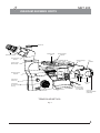
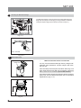
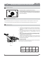
R
MET 400
User Manual
Inverted Metallurgical Microscopy
To ensure proper use of this instrument as well as to avoid injury while operating
instrument, understanding this manual completely before use is highly recommended.
CONTENTS
1
INTRODUCTION
1
2
SAFETY INFORMATION
2
3
UNPACKING YOUR MICROSCOPE
3
4
MET 400 TRINOCULAR DIAGRAM
4
5
INSTALLING THE INCIDENTAL LIGHT ILLUMINATOR
5
6
INITIAL SETUP & ASSEMBLY
7
DETAILED BRIGHT FIELD OBSERVATION PROCEDURE
8
DETAILED OBSERVATION PROCEDURE
10
9
OPTIONAL ACCESSORIES
11
10
CARE & MAINTENANCE
12
11
SPECIFICATION
13
12
TROUBLESHOOTING
14
6-8
9
1
INTRODUCTION
The MET 400 inverted microscope sets a new standard for inverted metallurgical microscopes.
It combines high performance and distinctive styling with the high quality craftsmanship for which Labomed is known. The
excellent image and comfort of use are the basics of Labomed MET400.
The ergonomics of the design, an aesthetically configured MET400 is the instant choice for Metallurgical Studies & relative
sciences. Offered with Infinity Corrected True color optical system, choices of observation tubes, soft feel
turret movement, stage with micro manipulation offer a paramount performance.
The user should be aware that the protection provided by the equipment may be impaired if used with accessories not
provided or recommended by the manufacturer or used in a manner not specified by the manufacturer.
1
2 SAFETY INFORMATION
MET 400
1.
It is important to follow Safety Instructions carefully to avoid any kind
of personal injury or damage to this Instrument. It is recomended for
your safety to read the manual throughly & do not discard this
manual rather preserve it for easy reference while operating for best
results.
2
To avoid potential electrical hazards when replacing halogen bulb,
turn the microscopes main switch to the OFF position and
disconnect power cord from wall outlet in advance. Whenever you
replace your microscope bulb, allow lamp socket and bulb to cool
before touching (Fig. 1)
Fig. 1
Applicable bulb replacement: 6V30W Halogen bulb P/N EL-455;
Safety Symbols
The following code categories describe the degree of danger or damage likely to be incurred in the event of
user error made in ignorance of these symbols.
Symbol
Explanation
Hot parts symbol.
This symbol is placed on bulb housing and on other parts to indicate that they
may be hot. Never touch those parts just after the equipment has been used.
Allow sufficient time to cool before touching them. In the event of user error,
it is possible to injury.
WARNING
!
ATTENTION
In the event of user error, death or serious injury is possible.
In the event of user error, product may be damaged.
The following describes icon directives
!
This icon denotes “Refer to User Manual” and “Caution”.
This icon represents the productive earth.
This icon represents alternating current.
This icon represents the power switch is turned OFF.
This icon represents the power switch is turned ON.
Labeling Infromation
SN
Number following this symbol indicate the serial number of the equipment.
REF
Character following the symbol indicate the catalog number of the equipment.
2
3
MET 400
UNPACKING YOUR MICROSCOPE
MET400 comes securely packed in the custom configured foam packing, to prevent it from all shocks and
transit damages.
After removing your Microscope from its packing, make sure that all of the following contents are present.
“Please note that the contents of your Microscope may vary as the optional configuration, contrasting method
or viewing body opted for may not be of the standard configuration highlighted here”:
1.
Microscope body
2.
Observation tubes, as ordered
3.
Eyepieces Pair
4.
2 Filter Sliders (ND & NCB)
5.
Stage Plate (fitted on Body)
6.
Objectives Set - Standard 5x, 10x, 20x & 50x
7.
Epi Illuminator assembly with Two Filter Slots
8.
Installation tools Allen Key - 3mm
9.
Power Cord
10.
Mechanical Stage (Optional) if ordered.
11.
Specimen Holder Plate
12.
Three different size of Petri Dish holders
13.
Two Hand Rests
3
4
MET 400
DIAGRAM SHOWING PARTS
Camera Port
Specimen Holder
Plate
Eyepieces (Focusable)
Mechanical Stage
(Optional)
Observation Head
Binocular
Aperture diaphragm
Lever
EPI
Illuminator
Screw For Fixing
Binocular head
Revolving Turret For
Objectives
Light Intensity
Control knob
2 Filter Sliders
Control Knobs
For Coarse & Fine
Focusing
Coaxial Control
Knobs For Stage
X & Y Movement
ON / OFF Switch
Lamp House
Cover
Lamp Holder
(Removable For Bulb
replacement)
TRINOCULAR MET-400
Fig. 2
4
5
MET 400
Installing the Incidental Light Illuminator
Illuminator
The Illuminator Unit is to be fixed to the main Microscope Body with 3 screws using Allen wrench supplied along with
Illuminator. Three Tapped Holes are provided in the Base Unit as shown in Diagram below.
Important Note:
Make sure the Power Cord is not connected at this stage.
After the Illuminator Assembly is properly fixed, connect the cable from Lamp House to the Socket provided in Base of
Microscope as shown in below picture.
Aperture Diaphragm lever
3 tapped holes
EPI Illuinator Cable
connecting to above
Fig. 3
Adjusting the Aperture Diaphragm
In order to achieve good resolution of the optical image, the contrast and depth of focus it is necessary to control the numerical
aperture of the Illumination system through the lever provided on the illuminator - See Diagram above.
Reducing the aperture increases the contrast & the depth of focus. Increasing the aperture increases the brightness &
resolution.
1.
2.
3.
4.
Place a specimen with plain surface on the stage.
Focus on the specimen with 10x Objective.
Remove one of the Eyepiece & look through the Eyepiece Tube to ensure the diaphragm image is visible in the
pupil of the Objective
It is recommended to keep the Aperture Diaphragm image in nearly 3/4th of the pupil of Objective. Adjust with
aperture lever your required image quality.
5
6
1
INITIAL SETUP & ASSEMBLY
Observation Head
Base unit is assembled with co-axial focus mechanism, turret and stage
plate, as per procedure below:
Install the observation head using the following procedure as shown in
INITIAL SETUP &
Fig.ASSEMBLY
4:
1.
2.
3.
Fig. 4
2
Using the 3mm allen wrench (provided), loosen the Head
Locking Screw (1) and remove the dust cover cap provided in
dovetail cavity as well as on the observation head dovetail.
Mount the Observation Head by engaging the dovetail provided
at the bottom of the head into the dovetail cavity provided in the
microscopes arm.
Tighten the Head Locking Screw (1) after positioning the
Observation Head as desired. See figure 4.
Mounting the Objectives
Settle down the nosepiece by rotating coarse adjustment knob towards
back. Remove the dust prevention caps from the nosepiece.
Screw the objective with the lowest magnification into the revolving
nosepiece from the left side of the microscope. Turn the nosepiece
clockwise and mount the remaining objectives in ascending
magnification order. (Fig. 5)
!
!
Clean the objectives periodically.
Be sure to cover any unused threaded position on Turret
with the dust prevention caps to prevent from dirt and dust
from getting inside.
Fig. 5
3
Mounting of Eyepieces
Insert the eyepieces into the ocular tube of Observation Head after
removing the protective caps from the observation tube.
For Dioptre Adjustment on Eye Piece See Page 7
Fig.6
6
4
Adjusting the Interpupillary Distance (IPD)
The inter-pupillary distance adjustment consists of regulating the two
eyepieces to align with both the eyes’ pupils so that you can observe a
single microscopic image through two eyepieces in stereo vision. This
greatly helps to reduce fatigue and discomfort during observation.
While looking through the eyepieces, move both eyepieces laterally until
the left and right fields of view coincide completely. The position of index
dot (•) indicates the inter-pupiliary distance value.
Fig. 7
5
Note your interpupillary distance so that it can be quickly referred to in the
future. This is especially important if multiple users work with the
microscope.
Adjusting the Diopter
Adjust the Diopter setting to “0” position by matching the fiducial lines on
both eyepieces. Now looking through one eye piece (either left or right),
turn the coarse and fine focus adjustment knobs to bring the specimen into
focus.
Adjust the focus of other side of eye piece by looking through it and at the
same time optimizing the Dioptre scale of the Eye Piece.
Fig. 8
Using the Eye Guards
When Wearing Eyeglasses
Use with the eye guards in the normal, folded-down position. This will
prevent the eyeglasses from being scratched (Fig # 9 Part 1).
1
When Not Wearing Eyeglasses
Extend the folded eye guards outwards (direction of the arrow) to prevent
ambient light from entering into your line of vision (Fig # 9 Part 2).
2
Fig.9
7
MET 400
7
Mounting the Mechanical Stage
The Mechanical stage is to be mounted on the Right Side of Square
Stage with the help of two clamping screws (provided) underneath
of the plain square stage (shown with arrow marks on Fig 10.1)
Fig. 10.1
Ref. # 7121300
Mounting
Holes
Fig. 10.2
5.0
8
Adjusting
Bulb
Replacement
the Interpupillary Distance and Diopter
*
Guide hole
Make sure the Power Cord is not connected.
Use only recommended 6V-30W high intensity Halogen bulb.
Applicable bulb replacement 6V-30W Halogen Bulb P/No.
Ref. # EL-455.
Pull out the lamp socket and pull out the blown bulb using a soft
cloth. Gently insert the new bulb. Do not squeeze or press the
bulb too much as it can cause damage to the bulb and hand.
Fig. 11
Fit the lamp socket by aligning the guide pins with the condenser
guide holes. Push the lamp socket gently into the transmitted
light illuminator. (Fig. 11, 12)
Guide
pins
Fig. 12
8
7
MET 400
SUMMARY OF BRIGHTFIELD OBSERVATION PROCEDURE
Click the main switch to “ON”
Place the specimen on the stage. Polished
surface facing the objectives below.
On/Off
Engage the 10X objective in the light path.
Adjust the observation tube and eyepieces
Adjust the interpupillary distance.
Adjust the dioptric setting.
Adjust the aperture iris diaphragm Epi Illuminator (Ref. Fig on Pg. 7
Engage the objective to be used in the light
path and bring the specimen in focus.
Engage the required filters.
Adjust the brightness.
Observe Specimen.
9
MET 400
8
1
DETAILED OBSERVATION PROCEDURE
Turning the Lamp ON
1. Click the main switch to ”I” (ON) as shown in Figure 17.
2. Rotating the light intensity adjustment knob in the direction of the arrow
increases the brightness and rotating the knob in the opposite direction
decreases the brightness. The intensity bar on the knob indicates the
direction of intensity level.
-
0
Fig. 13
2
Placing specimen on the stage
Place the Metallurgical specimen on the stage plate. The specimen should have sufficient polished - reflective surface.
In case your microscope has mechanical stage mounted, use appropriate holder plates. (See details on Page 13)
3
Adjusting the Focus
Focusing Procedure - use of Coarse focus knob & Fine Focus Knob.
1.
3
Rotate the coarse adjustment knob (1) clockwise so that the objective
(3) is as close as possible to the specimen (We recommend starting
with 10X).
2. While observing the specimen through the eyepieces, slowly rotate
the coarse adjustment knob (1) counterclockwise to lower the
objectives.
3. When coarse focusing of the specimen is obtained (an image is
observed), rotate the fine adjustment knob (2) for fine detail focusing.
4. Adjusting Torque for Coarse Focus Knob.
Rotation of tension adjusting ring towards coarse knob will increase
focusing torque. Rotating tension adjusting ring towards stand will
decrease the focusing torque.
Working Distance (WD)
The WD refers to the distance between each objective and the specimen,
when acute focus of the specimen is obtained.
4
2
1
Fig. 14
Objective
Magnification
WD (mm)
5X
10X
20X
50X
17.5
6.8
11.1
8.2
10
9
OPTIONAL ACCESSORIES
System Diagram of Optional Accessories
Video adapter
DSC adapter
iVu 3100
Binocular head
iVu 5100
Trinocular head
WF 16x
WF 10x
LW 5x
Ergonomic head
WF 20x
LW 10x
LW 20x
LW 50x (SL)
Mechanical stage
Dia: 25mm
Dia: 38mm
Dia: 53mm
Installation and Operation of Optional Accessories
1
iVu Camera Module System
1.
2.
Side View
Mount the Video adapter ½” (Ref. t # 3143300-712) on Trinocular
observation head.
Mount iVu Camera Module System on video adapter.
Back View
Fig. 15
11
MET 400
10
14
Care & Maintenance
Your microscope has been engineered for a long and safe operational life with the least amount of maintenance
required. In general, routine maintenance is limited to keeping the microscopes working parts lubricated and optics
clean. Always cover the microscope with the provided dust cover when not in use.
1. Optical Cleaning:
1. The objectives have been adjusted for a tight fit to prevent any damage during transportation. To remove an
objective, rotate it counterclockwise while gripping it with a rubber sheet, etc. to avoid any slippage.
2. To clean the lens surfaces, remove dust using a soft brush or compressed air (cans available at your local
electronics store). For removing finger marks or grease, soft cleaning cloth or lens tissue lightly moistened with
cleaning solution (85% petroleum ether and 15% isopropanol) should be used. For cleaning the objective optics,
use Methanol. Observe sufficient caution in handling Methanol. Place the objectives and/or eyepieces on a dustfree surface (e.g. aluminum foil). All other optical components to be cleaned should be as accessible as possible.
3.. Blow all loose dust particles away with compressed air or mini dust blower.
4. Remove all water-soluble dirt with distilled water. If this is unsuccessful repeat using a solution of diluted hand
soap liquid. Remove any remaining residue with a dry cotton swab.
5. To remove oil, use a solution of diluted hand-soap liquid initially. If this does not produce a satisfactory result,
repeat the cleaning using a solvent (Optical Cleaning Solution 85% petroleum ether and 15% isopropanol).
6. Grease must always be removed using a solvent.
7. Cleaning is achieved by using a spiral motion from the center to the rim. Never wipe using zig-zag movements as
this will only spread the dirt. With larger optical surfaces (e.g. tube lenses) the spiral motion starts initially at the rim
before moving to the middle and is then followed by a center to rim cleaning motion. Normally several spiral wipes
are recommended.
We recommend pure, volatile petroleum ether or Optical Cleaning Solution as explained in point 3 above.
zig-zag motion (X)
spiral motion ( )
Wipe using a spiral movement. Do not use a zig-zag motion!
2. Cleaning of painted surfaces :
Avoid the use of any organic solvent ( e.g. thinner, xylene, ether, alcohol etc.) for cleaning of painted surfaces of
the instrument. Painted surfaces can be cleaned with a very lightly moistened micro fiber cloth. Loose dust and
other dirt particles can be removed using a soft bristle brush used exclusively for this purpose.
12
MET 400
11 TECHNICAL SPECIFICATIONS SHEET
1. Illumination
Built-in Incident illumination system Halogen Lamp 6V-30W.
2. Focusing mechanism
Stage height adjustment mechanism
Fine adjustment scale: 0.002mm per graduation; Fine adjustment stroke: 0.2mm per
turn
Total stroke: 20mm
Co-axial coarse and fine focusing on ball drive
3. Revolving nosepiece
Quadruple positions fixed
4. Observation tube
5. Stage
Binocular
Trinocular
Ergonomic
Field number
22
22
22
Tube tilting angle
30°
30°
0°to 25°
Interpupillary distance
adjustment range
52-75
52-75
52-75
Size
240 x 160mm
Movement range
78 x 54mm with Mechanical Stage.
Specimen holder
3 Different Shapes.
7. Dimensions & Weight
495.0mm (L) x 300.0mm (W) x 470mm (H); 9.5 kg net
8. Electrical
Lamp
Halogen, 6V-30W
Lamp life
up to 100 hours
Input
100V-240V AC, 50/60 Hz
9. Operating environment
Indoor use
Altitude: Max. 2000 meters
Ambient temperature: 5° to 40°C (41° to 104° F)
Maximum relative humidity: 80% for temperature up to 31°C (88°F),
decreasing linearly through 70% at 34°C (93°F), to 50% relative humidity at 40°C
(104°F)
Supply voltage: 100 VAC TO 240 VAC
Supply voltage fluctuations: Not to exceed ±10% of the normal voltage.
Power consumption: 50W; Fuse: F5A/250V
Power supply to the halogen lamp: 6V AT 30W
Pollution degree: 2 (in accordance with IEC60664)
Installation/Overvoltage category: II (in accordance with IEC60664)
CAUTION: HIGH VOLTAGE
FUSE REPLACEMENT
WARNING: HIGH VOLTAGE
POWER INLET
EARTH
WARNING: HIGH TEMPERATURE
13
12
TROUBLESHOOTING GUIDE
Under certain conditions, performance of the unit may be adversely affected by factors other than defects. If problems occur,
please review the following list and take remedial action as needed. In case of any other problem which cannot be rectified as
below, please contact the service agents.
Cause
Trouble
1. Although the Power is on, the field of
view is dark.
2. Dirt or dust is visible in the field of view.
3. Visibility is poor.
- Image is not sharp.
- Contrast is not sharp.
- Details are indistinct.
4. One side of image is blurred.
5. The bulb flickers and the brightness is
unstable.
6.The coarse adjustment knob is too
difficult to rotate.
7.The field of view of one eye does not
match that of the other.
Remedy
The socket pin is not connected from the
illumination column to the back of the
instrument.
Connect it securely.
The bulb is burned out.
Replace the bulb.
The light intensity control is set to too low.
Set the illumination to desired position.
The objective is not in position.
Make sure the objective is clicked
properly.
Fuse is blown.
Replace fuses (250V / 5 Amps)
Dirt/dust on the specimen.
Clean the specimen.
Dirt/dust on the eyepieces.
Clean them thoroughly.
The specimen is not correctly engaged.
Replace it with a clean specimen.
The aperture iris diaphragm is opened or
stopped down too far in brightfield
observation.
Clean eyepieces gently.
Adjust the aperture.
The revolving nosepiece is not correctly
engaged
Make sure that the revolving nosepiece
clicks properly into place.
The specimen is not correctly mounted
on the stage.
Place it correctly on the stage.
The line voltage fluctuates
Use a voltage stabilizer.
The bulb is nearly burned out.
Replace the bulb.
The power cord is not connecting securely.
Connect it securely.
The tension adjustment ring is tightened
too much.
Adjust it appropriately.
The tension adjustment ring is loosened
too much.
Tighten it appropriately.
Incorrect interpupilary distance
adjustment.
Adjust the interpupilary distance.
Incorrect diopter adjustment.
Adjust the diopter.
14
www.laboamerica.com
Our policy is one of continuous development. Labo America, Inc., reserves the right to change design and specifications without prior notice.
Labo America Inc.
920 Auburn Court.
Fremont
CA 94538
U.S.A.
Telephone: 510 445 1257
Fax: 510 991 9862
[email protected]
LABOMED and TCM 400 are registered trademarks of Labo America, Inc.
With a policy of continuous development, Labo America, Inc. reserves the right to change design and specifications without prior notice.
© 2009 Labo America, Inc. | 7125000-990A 12-2009
ISO 9001 : 2008
File No. A9020