1
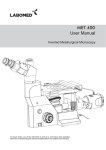
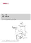
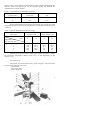
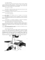
STEREOSCOPIC MICROSCOPE MBS-10
Maintenance manual
1
ATTENTION! The microscope design can be somewhat differ from
those described in this maintenance manual.
2
1 PURPOSE
The MBS-10 microscope is intended for observing both threedimensional and thin-film and transparent objects as well as for performing
preparatory operations.
The observation can be performed both in artificial and natural
illumination in reflected and transmitted light.
Field of application: botany, biology, medicine, mineralogy,
criminalistics, archeology, mechanical engineering, instrument making industry
and other fields of science and technology.
2 SPECIFICATIONS
2.1 Magnification, times, in the range
2.2 Linear field of vision, mm, in the range
2.3 Operating distance, mm, no less
2.4 Illumination source
2.5 Overall dimensions in operating state
(disregarding elbow-rest, eyepiece, illuminator),
mm, no more: length
width
height
2.6 Mass of device, kg, at most
2.7 Mass of device in packing, kg, at most
4–100
39–2.4
95
halogen lamp 12V/20W
265
160
475
8
11
Information of precious and non-ferrous metals content
Aluminum – 4.092 kg
Copper – 0.34 kg
Zinc – 0.053 kg
3 COMPONENTS
3.1 Body with drum
3.2 Binocular attachment
3.3 Table for operating in reflected light
3.4 Table for operating in transmitted light
3.5 Power supply unit
3.6 Objective f’=90mm
3.7 Illuminator
3.8 Elbow-rest
1 pc
1 pc
1 pc
1 pc
1 pc
1 pc
1 pc
2 pc
3
3.9 Lamp-holder (to fix the lamp when operated in reflected light)
3.10 Eyepiece 8x
3.11 Eyepiece 14x
3.12 Eyepiece 8x with scale
3.13 Eye shield
3.14 Halogen lamp 12V/20W
3.15 Light filter
3.16 Clump
3.17 Preparation glass
3.18 Plate
3.19 Rubber strap
3.20 Flannel cloth
3.21 Maintenance manual
3.22 Case
3.23 Case for spare parts
3.24 Packing box
3.25 Fused plug VP-1V 1.0 A/250 V
3.26 Fused plug VP-1V 3.15 A/250 V
1 pc
2 pc
2 pc
1 pc
2 pc
1 pc
1 pc
2 pc
1 pc
1 pc
1 pc
1 pc
1 copy
1 pc
1 pc
1 pc
2 pc
2 pc
4 DESIGN AND OPERATING PRINCIPLE
4.1 Microscope Optical Train
An object image is formed due to the successive rays transmission
through the f’=90mm objective 16; pair Galilean systems, set in the drum placed
in the body placed in the body 1; tubules lenses and Schmidt prisms, been in the
binocular attachment 5 and changeable eyepieces, which installed into the
eyepieces tubes 11 (Figure 1).
Galilean systems are alternatively switched on into the light beam path
and allow realizing four versions of the microscope object part magnifications.
The fifth version of magnification comes out if the Galilean systems are switched
off from the light beam path.
Magnifications values of the objective part of the microscope are given in
Table 1.
Table 1 - Magnification of objective part
Linear
magnification
of
1/3.5
Galilean system, mult.
General linear magnification
0.6
of objective part
1/2
1
2
3.5
1
2
4
7
The microscope is delivered with two pairs of changeable eyepieces
(characteristics are given in Table 2) and eyepiece 8× with changeable scale and
4
dioptric setting. The eyepieces are used for observing the image reproduced by the
objective part of the microscope. On the eyepieces bodies are indicated the
magnifications in round numbers.
Table 2 – Characteristics of changeable eyepieces
Magnification of
Diam. of linear field of
eyepiece, mult.
vision, mm
Range of output pupil,
mm
8
23.0
18.0
14
16.0
16.0
Optical characteristics of the microscope with the use of each pair of the
changeable eyepieces and of all the magnifications of the objective part are given
in Table 3.
Table 3 - Optical characteristics of the microscope
Characteristics of the
Magnification of
microscope
eyepiece, mult.
Magnification of eyepiece,
mult.
8
14
Magnification of
objective part, mult.
0.6
4.8
8.4
1
8.0
14.0
2
16.0
28.0
4
32.0
56.0
7
56.0
100.0
Field of vision in the
plane of object, mm
8
14
39.6
23.0
11.2
5.6
3.2
29.7
16.8
8.4
4.2
2.4
Schmidt prisms present a direct image of the object and allow to change
the instrument interpupilary distance from 56 to 72 mm depending on the
observer’s eye.
4.2 Construction
The general view of the microscope is given in Figure 1. The microscope
consists of the following basic units:
– optical head;
– microscope table;
– power supply unit.
5
Figure 1 – General view of the microscope
1 – body with drum; 2 – table for operating in reflected light; 3 – table for operating in
transmitted light; 4 – dioptric setting ring; 5 – binocular attachment; 6 – handle of
interpupilary distance change mechanism; 7 - table lock; 8,17 – screws, fixing the binocular
attachment and objective f’=90mm; 9 – illuminator bush; 10 – illuminator nut;
11 – eyepiece tube; 12 – mirror and clouded glass in mount; 13 – handle of magnification
switching; 14 – light filter; 15 – stand; 16 – objective f’=90mm; 18 – preparation glass;
19 – arm; 20 – elbow-rest; 21 – clamp; 22 – focusing handle; 23 – throw control;
24 – power supply unit; 25 – ring
The optical head consists of the body with the drum, the objective
f’=90mm, the binocular attachment, the illuminator.
The microscope table consists of the table for operating in reflected light
and the table for operating in transmitted light.
The necessary magnification is setting by rotation the handle 13 (Figure
1) to match the digit on the handle with the index point on the ring.
The focusing of the microscope on the object is carried out by the optical
head traveling relative to the microscope table along the guide line of “dovetail”
type by rotation the handles 22 (Figure 1).
ATTENTION! Rotation of focusing handles and magnification change
handles in the opposite directions is prohibited.
Throw control of focusing handles from slight to stiff is fulfilled by
revolving the handle 23 (Figure 1).
6
4.2.1 Body with drum
In the body of the optical head incorporates the drum with the Galilean
systems. Rotating the handles 13 (Figure 1) which are fixed on the drum shaft
changes over the value of magnification. On the handles 13 are indicated the
magnifications in round numbers (7, 4, 2, 1 and 0.6 mult.).
4.2.2 Objective f’=90mm
The objective is fixed to the body of the drum by the bayonet joint. The
fixing of the objective is fulfilled by the screw 17.
ATTENTION! To prevent dropping of the objective the screw 17 should
always be screwed against the stop.
4.2.3 Binocular attachment
The objectives and Schmidt prisms are installed in the binocular
attachment 5 (Figure 1).
The changing of interpupilary distance is fulfilled by rotation the Schmidt
prisms in the opposite direction by the screw mechanism that is put in motion by
handle 6 (Figure 1).
ATTENTION! It is absolutely prohibited to change the interpupilary
distance by moving the eyepiece tubes toward and apart by hand.
The changeable eyepieces are installed in the eyepiece tubes.
On the left eyepiece tube is a mechanism of dioptric focusing which is
fulfilled in the limits of ±5 diopters by rotation the ring 4. The diopters nought is
installed at the combination of index on the dioptric ring 4 with a mark on
eyepiece tube.
The binocular attachment is fixed to the body by the bayonet joint. Its
fixing in the seat is fulfilled by the screw 8.
4.2.4 The microscope table
On the stand 15 of the microscope table is fixed the optical head by the
clamping screw which should always be tightened. To prevent an accident
dropping of the optical head and for improvement of illumination in the right and
left branches of the microscope on the stand is a clip 28 (Figure 2), fixed in the
required position by screw 26 (Figure 2). The table has a round window (see
Figure 1), in which the preparation glass or the plate 18, two holes for the
clamp 21 and three holes for the substage ST-12 setting are installed, the latter is
7
Figure 2 – The microscope table
not included in the microscope standard equipment and is purchased separately.
The one side of the plate 18 is white and is intended for observing dark objects,
the other side is black and is intended for observing light objects. The table 2 for
operating in reflected light is mounted on the table 3 for operating in transmitted
light and is fixed by the lock 7, faced to the front open side of the table body.
There are mirror and clouded plate in mount 12 in the table 3. Their rotation is
fulfilled by knob 27 (Figure 2). The table rear wall has a seat for fixing the
illuminator in operating with reflected light. The side walls of the table have seats
for mounting the elbow-rests.
4.2.5 Illuminator
If operating at reflected light the illuminator is installed in the arm seat
19 (Figure 1) which makes possible to illuminate the object under different angles
and from different sides. The arm 19 can be fixed in the required position by
rotation the ring 25.
The disassembled illuminator is represented in Figure 3 and consists of
the lamp 1, the body 2, the seat flange 3, the chuck 4, the spring 5, the flex 6, and
the bush 7.
The microscope equipment has a light filter that is united through the
thread to the seat flange 3 of the illuminator.
The illuminator power can be controlled changing lamp power voltage.
8
Figure 3 – Illuminator
When replacing the lamp it is necessary, keeping safety precautions listed
in the paragraph 5.3, to weaken the flex 6 fixing (see Figure 3) by the bush 7
(counterclockwise rotation), screw the seat flange 3 out, remove the flex with the
lamp 1 and with the chuck 4 out of the body 2, replace the lamp in the chuck. The
assembling should by made vise versa.
4.2.6 Power supply unit
The power of the illuminator lamp is provided through the power supply
unit 24 (Figure 1) from alternating current mains 0f 220 V using the flex with the
plug of the side ground contact. The cover of the power supply unit has a
connecter of 12V for the illuminator switching on (by means of two prongs). The
side walls of the power supply unit have toggle switch, lamp voltage regulator,
holders of safety devices (of fused plugs) of 1.0A and 3.15A.
5 SAFETY PRECAUTIONS
5.1 The instrument is intended for indoor operation under conditions of
absence of increased electrical danger. The conditions increasing the mentioned
danger are:
a) increased humidity and dustiness of air;
b) current-conducting floor: metal, brick, reinforced-concrete;
c) temperatures above 400C.
5.2 Regularly, before connecting the instrument to the power mains, the
safety of the cord insulation, power supply unit and illuminator should be checked.
5.3 The lamp and fused plugs (safety devices) removing is required to
make under de-energized illuminator and power supply unit.
9
6 PREPARATIONS FOR USE
If the instrument is delivered indoors from cold, unpack it six hours after
bringing it inside.
After unpacking the instrument is needed to be prepared for the operating
for which is purpose:
a) install the body with the drum on the stand 15 and tighten the screw;
b) install the binocular attachment in the bayonet seat of the body with
drum and tighten screw 8. In operating with artificial lighting the binocular
attachment 5 should be installed as it is shown in Figure 1. At the natural lighting
it is necessary to rotate the binocular attachment at 1800C;
c) install the objective f’=90mm and tighten screw 17;
d)install the lamp in the lamp holder of illuminator and adjust
illumination as instructed in paragraph 4.2.5;
e) choose the pair of eyepieces of required magnification (see Table 2);
f) install the eye shield that is included in the microscope standard
equipment;
g) check up the correspondence of magnification to the reading on the
handle 13. Proceed as follows:
1 Take the binocular attachment 5 off.
2 Install the drum so that through the seat under the binocular attachment
should be seen the apertures in the drum without optics and at both sides of these
apertures should be seen the mounts with the small optics of the drum.
3 The index on the ring must coincide with figure 2 at the handle of the
drum that is between 7and 4. If index don’t coincide with the indicated figure,
return the ring with the index around its axis to combine with the indicated
figure 2.
7 OPERATION PROCEDURE
7.1 General Indication
Focus the microscope on the object by rotation the handle 22 (Figure1).
Install the interpupilary distance according to the base of observer’s eye, by
turning the handle 6.
When operating at the large magnifications use the handle of throw
control 23 at the focusing on the object. Choose the position of illuminator by
turning it with the arm about the objective and choose the handy angle of slope.
The dioptric focusing must be used after the microscope has been focus
on the object on the right branch that doesn’t have the dioptric focusing.
7.2 Operation with Eyepiece 8x with the Scale
10
The eyepiece has a mechanism of dioptric setting. The scale is set in the
focal plane; grid, which is delivered under the special order, can be set instead of
the scale. The name of grid for special order “Grid in box. IAZU. 305648.010”
The scale and the grid are actually plane-parallel glass round plates. The scale
division value is 0.1mm; the grid square side value is 1.0mm
To perform linear measurements or measurements of various object
areas, insert the eyepiece 8x with the scale into the one of the eyepiece tubes of the
microscope. By the mechanism of dioptric setting of the eyepiece obtain a sharp
image of the scale or the grid (depending on what is installed). Then, rotating the
knob of the focusing mechanism obtain the sharp image of the object. The table 4
shows to what actual value of the object corresponds one division of the scale or
the grid at all values of magnification of the microscope.
Table 4 - Conversion table of the microscope magnifications
Scale one division,
Square side, 1mm
Magnifications in round numbers
0.1mm
on the handles of the drum, mult.
Corresponds to actual value of the object
0.6
0.17
1.7
1
0.1
1.0
2
0.05
0.5
4
0.025
0.25
7
0.014
0.14
In order to determine the approximate dimensions of the object (its linear
dimensions or area) it will suffice to count the number of the division of the scale
which are laid in the measured section of the object and to multiply the obtained
result by the number indicated in the conversion. Table corresponding to the
magnification of the microscope at which the measurement is being performed.
To replace the scale (or the grid), proceed as follows:
1 turn the scale rim out of the eyepiece body. The rim is found in the
bottom part of the eyepiece;
2 turn out the nut fastening the scale (or the grid) and remove
carefully the scale from the rim;
3 install the grid into the rim and tighten up the nut;
4 turn the rim into the body of eyepiece.
8. MAINTENANCE
When receiving the microscope pay attention if the Manufacturer’s seal
is intact.
The microscope leaves the Manufacturer duly tested and can operate free
of trouble for a long time, provided it is kept clean, properly cared of and
11
prevented from any kind of mechanical damage. The Manufacturer’s package
ensures safety of the microscope during its transportation. When not using, the
microscope should be covered by the case.
To keep the microscope good appearance, it should be wiped
periodically, excepting optical surface, by a soft cloth impregnated by acid-free
vaseline after which the instrument should be dried by a soft clean cloth.
If after a certain time the grease in the focusing mechanism guides
becomes dirty and thick, remove it by using xylene or benzene, wipe the friction
surfaces with a clean soft cloth and greasy slightly the guides with the acid-free
vaseline or special grease. Pay special attention to the cleanness of the microscope
optical elements. During the operation the optical surface has to be prevented from
moisture.
To prevent the prisms surfaces from dust, the eyepieces should be always
left in the eyepieces tubes of the microscope. The eyepieces have to be also
prevented from dust.
The lenses surfaces should not be touched by fingers and hard objects in
order to avoid a spoilage of coated surfaces.
When cleaning the lenses surfaces, dust and other soiling should be
removed by using a soft clean cloth. If after that the optical surfaces are
insufficiently clean, use a soft batiste cloth slightly moistened by spirit.
9 ACCEPTANCE CERTIFICATE
The MBS-10 microscope, serial No______________________________
meets the technical specifications and has been found fit for service.
QCD Representative
«___» _________________200
10 PRESERVATION AND PACKING REPORT
The MBS-10 stereoscopic microscope, serial No____________________
has been subjected to preservation treatment and duly packed at the
Manufacturing factory in compliance with the requirements prescribed by the
technical documentation.
Preserved and packed on ____________________________
Preservation and packing were made by ________________
295-03
12
STEREOSCOPIC MICROSCOPE MBS-10
Maintenance manual
13


![KeyView [4823353_1.wpd]](http://vs1.manualzilla.com/store/data/005667242_1-589c8deb81b55e7c0d34a0d078158765-150x150.png)