1
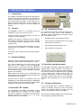
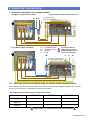
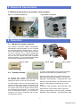
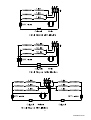
SCREENZONE
RECESSED WARM AIR CURTAINS
CATALOGUE NUMBERS
RAC0603, RAC0604, RAC1006
RAC0603RF, RAC0604RF, RAC1006RF
INSTALLATION AND OPERATING MANUAL
INDEX
Section
General Information ----------------------------------------------------------- 1
Dimensions ---------------------------------------------------------------------- 2
Installation Details -------------------------------------------------------------- 3
Operation ------------------------------------------------------------------------ 4
Electrical Connections -------------------------------------------------------- 5
Servicing & Maintenance ----------------------------------------------------- 6
Consort Equipment Products Limited
Thornton Industrial Estate, Milford Haven
Pembrokeshire, SA73 2RT
Tel: 01646 692172 Fax: 01646 695195
Email: [email protected] Web: www.consortepl.com
41000942 Iss 06
1. General Information
CLAUDGEN Wireless controllers
1.1 Introduction
The heaters are designed for discreet positioning in
a suspended ceiling or bulkhead in the doorways of
retail or commercial premises. Overall energy saving is likely when the heater is sited above a frequently opened external door as the airstream can
prevent heat loss. Will fit a recess as shallow as
195mm.
1.2 General
1.4 RF Controller Location
All installations must be in accordance with the
regulations in force in the country of use.
It is essential the Controller should be positioned on
the wail in the same room as the aircurtain. It
should be where its temperature will not be change
with local effects. Avoid:
These instructions must be handed to the user on
completion of the installation.
Installers and service engineers must be able to
demonstrate competence and be suitably qualified
in accordance with the regulations in force in the
country of use.
To ensure continued and safe operation it is recommended that the appliance is serviced annually.
( See 7.1 )
•
Draughty places near windows or doors
•
Places near the aircurtain itself or any other
heat sources in the room
•
Place where the sun will shine on it
•
Places where it may get wet
The heater outlet / inlet must not be obstructed during use.
1.3 Electrical Supply.
Electrical supply is 230/240V single phase, Neutral
and Earth. The maximum cable inlet size is 4mm².
It is recommended that the electrical supply to the
base unit in the heater is via an appropriate
switched isolator in accordance with the regulations
in force in the country of use and must be via a
fused isolator having a contact separation of greater
than 3mm on all poles.
1.5 Controller standard models
The RAC0603, RAC0604, RAC1006 heaters are
supplied with a remote controller. The remote control unit houses 3 double pole 20A rocker switches.
The heater can also be controlled remotely via BMS
or any controls with contact rated at 20A for
RAC0603, RAC0604 and 30A for RAC1006. The
controller is wired to the base unit via an appropriate sized cable specified by the current IEE standard.
BMS control, time switches, room thermostats and
door interlocks can be installed at the discretion and
responsibility of the installer.
All units must be wired in accordance with I.E.E
regulations for the Electrical Equipment of Buildings
and the installer should ensure that a suitable isolating switch is connected in the mains supply.
1.5 Clearance Distances
It is recommended that a minimum clearance of
100mm is allowed around the case and 55mm
above. The clearance allows for cable entry and
prevents combustible surfaces overheating.
1.4 Controller `RF` models
The HE7230RF, HE7245RF, HE7260RF heaters
are supplied without a controller. The `RF` models
will not work without the controller. There are three
wireless controllers to choose from in our range.
See section 6.1 for more details.
The minimum mounting height (floor to grille) is 2m.
The maximum mounting height is 3m.
2
41000942 Iss 06
2. Dimensions
2.1 Air Curtain Dimensions
3
41000942 Iss 06
3. Installation Details
3.1 Mounting
All units should be installed horizontally directly
over the door opening. It is recommended that the
air curtain is installed on the inside of the building,
within the open room space against a wall or
ceiling.
Care must be taken to allow complete free air
movement into the inlet grilles of the unit to ensure
correct working operation of the air curtain. The
discharge opening should be as close to the top of
the door as possible and cover the entire door
width.
Units can be mounted adjacent to each other to
cover the full door opening across wider
entrances.
ENSURE AIR OUTLET LOUVRES ARE NEAREST
TO THE DOOR APPERTURE.
The weight of the RAC0603 and RAC0604 is 8kg
The weight of the RAC1006 is 11.5kg
3.2 Electrical Installation
Fig.1 ceiling cutout for RAC0603 and RAC0604
These units are suitable for connection to 230/240
Volt 50 Hz single phase supply.
The appliance shall be connected to the supply
via an appropriate switched fused double pole
isolator having a contact separation of greater
than 3mm. Test for correct operation and refit the
grille.
For connection to the mains supply it will be
necessary to remove the grille from the unit. It will
be necessary to connect the mains supply and the
lead from the controls prior to refitting the cover.
Wire in accordance to wiring diagrams.
Fig.2 ceiling cutout for RAC1006
For safety reasons, a sound earth connection
must always be made to the unit before it is put to
use. The unit should be wired in accordance with
IEE Regulations for the Electrical Equipment of
Buildings.
Fig.3 Grille fixings detail
4
41000942 Iss 06
3. Installation Details
Fig.4 Fixing points
3.3 Installation
It is the sole responsibility of the installer to ensure
that the points of attachment to the building are
sound. Consultation with the consultant/architect or
owner of the building is recommended to ensure
that a sound, mechanically stable installation is
achieved.
Before fitting or wiring the air curtain, ensure the
outlet is facing the doorway as on the picture and
see the general installation guidance notes.
Fig.5 Wire fixing
Using a pozidrive screwdriver slacken the two M5
screws in the corners near air inlet side and remove
the two M5 screws in opposite corner near the outlet. Slide the lid sideways until the keyhole slots
pass over the screw heads. The grille assembly can
now be removed from the case.
Each unit has 2 fixing brackets from which it is suspended. The brackets may be removed to assist in
passing the air curtain through the recess then reattached when in-situ.
Either drop rods or catenary wire can be used to
fasten the air curtain to the ceiling support structure.
Fig.6 Rod fixing
The height between the ceiling face and the top of
the air curtain case needs to be adjusted to circa
140mm to enable the grille assembly to fit flush with
the ceiling. Adjust accordingly.
After fitting the product in the ceiling recess and adjusting the height to ensure that the grille sits flush
to the ceiling (when re-fitted) take the grille assembly and refit using the screws removed.
4. Electrical Connections
Fig.7 Grille Earth lead
4.1 Electrical connections
With grille removed, connect the electrical supply
and controls wiring to the appropriate terminals (see
relevant wiring diagram section).
The unit has four holes for the cable entry, two on
the top and two on the side. Cable entry may be
moved to alternative position if desired (see Fig.8
drawing).
Fig.8 Cable entry position
An EARTH lead is connected to the lid from the unit
body, push on connection at grille. When replacing
the grille onto the unit ensure the EARTH lead is reconnected. (see Fig.7 )
Electrical supply is 230/240V single phase, Neutral
and Earth. The maximum cable inlet size is 4mm².
5
41000942 Iss 06
5. Electrical Connections
5.1 Electrical connections for standard models
Fig.9 Mains supply direct to heater
Fig.10 Remote switch terminal side view
L connected by 30A
one way connector block
E N L
L
F
H1
H2
N
E
Fig.11 Mains supply via remote
-
Fan
Heating element 1
Heating element
Neutral
Earth
L
Two independent live
feeds must be used on
4,5kW and 6kW heaters as
shown on the diagrams
N
L
L
L
L
E
N and E connected by 30A
one way connector block
5.2 Electrical connections without using the remote switch standard models
If the heaters are to be controlled by means other than the remote switch supplied, eg BMS, then the heat
output can be selected by connecting the appropriate terminals.
Fig.12 Wiring of the heaters without using remote switch
WIRED TERMINALS
RAC0603
RAC0604
RAC1006
H1 + H2 + F
3000W
4500W
6000W
H1 + F
1000W
1500W
2000W
H2 + F
2000W
3000W
4000W
Please note the ‘F’ terminal must always be connected
6
41000942 Iss 06
5. Electrical Connections
5.3 Electrical connections for wireless control models
Fig.13 ‘L’ and ‘N’ connections
Fig.14 Earth connection
6. Operation
6.1 Models for wireless controls
The wireless controlled models RAC0603RF,
RAC0604RF and RAC1006RF can be controlled
by Claudgen wireless controllers CZC1, CZC2 or
CZC3. The heaters will not work without a controller. Each controller has a unique identification
code, it can control an unlimited number of heaters and will not interfere with other controllers
within the building. For more details please follow
the instructions supplied with the controller.
Fig.15 CZC1
6.2 Standard models
All standard RAC heaters
are supplied with a remote switch that gives the
following functions; On/off, fan only and heat.
For thermostatic control, a room thermostat of appropriate switch rating maybe connected to the
circuit. The thermostat should be wired between
the isolator switch and the heater remote switch.
For RAC0604 and RAC1006, or to control more
than one RAC0603 heaters by a thermostat, a
contactor or a relay in conjunction with the thermostat should be used.
Fig.16 CZC3
Fig.17 CZC2
To switch on the appliance and operate the blower,
depress the left-hand switch (marked “FAN”).
When the centre switch only (marked with a single
bar) is depressed the heat output is ⅓ of full heat.
RAC0603 - 1kW,RAC0604 - 1.5kW,RAC1006 - 2kW
When the right hand switch only (marked with a double bar) is depressed the heat output is ⅔ of full
heat.
RAC0603 - 2kW, RAC0604 - 3kW, RAC1006 - 4kW
When both the centre switch and the right-hand
switch are depressed the full heat output is available.
RAC0603 - 3kW, RAC0604 - 4.5kW,RAC1006 - 6kW
7
41000942 Iss 06
7. Servicing & Maintenance
7.1 Maintenance
ALWAYS ENSURE THAT THE MAIN EXTERNAL ELECTRICITY SUPPLY IS SWITCHED
OFF BEFORE COMMENCING ANY MAINTENANCE ON THIS HEATER.
If this happens, the thermal cut-outs effectively
switch off the appliance by disconnecting power to
the control circuit. The appliance will not operate
until the thermal cut-outs are manually reset. This
should be done by a competent electrician.
To obtain the best results from the heater, it is essential to avoid the accumulation of dust and dirt
within the unit on the air inlet and discharge grilles.
For this reason regular cleaning is necessary, paying particular attention to the removal of dirt build up
on the rotor blades.
The heaters are also protected by thermal fuses to
prevent catastrophic failure. The thermal fuse will
trip and disconnect power to the affected heater.
Thermal fuses are not resettable.
7.4 Fault Conditions
Cleaning of the fan is best carried out with a soft
brush.
If the heater will not operate, disconnect it from the
mains and arrange for a certified electrician to attend to investigate the reason.
The product should be serviced annually.
Servicing shall be undertaken by a competent person.
7.5 Replacing Fan Heater Assembly
Remove the lid.
7.2 General
Disconnect the internal wiring from the main terminal block. Remove the four nuts and washers fixing
the fan heater assembly to the back of the case.
The fan heater assembly can now be eased forward and removed from the heater case. Fit replacement fan heater and reassemble in reverse
order.
If the air curtain does not operate after switching on,
then a suitably competent service engineer should
be called to identify the nature of the fault.
All Air Curtains are fitted thermal cut-outs and motor
thermal protection.
Other faults in relation to the element, motor and
wiring should be identified using conventional fault
finding techniques.
7.6 Spares
It is essential when ordering spares or replacement
parts to state the model number and the serial
number on the rating place fixed to the top of the
unit.
In the event that electrical components are replaced,
please ensure that electrical safety checks in accordance with the regulations in force in the country of
use are undertaken.
In the interest of progress the Company reserve the
right to vary specifications from time to time without
notice. The material listed is offered subject to the
Company’s General Conditions of Sale, a copy of
which can be obtained on request.
7.3 Thermal and fault protection
The units are protected from overheating in the
event of fan failure or an obstruction of the free airflow by thermal cut-outs.
Consort Equipment Products Ltd
Registered Office: Thornton Industrial Estate
Milford Haven, Pembrokeshire, SA73 2RT
Tel: 01646 692172 Fax: 01646 695195
BS EN ISO 9001 Registered Company No FM12671
8
41000942 Iss 06
9
41000942 Iss 06
10
41000942 Iss 06