1
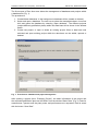
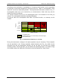
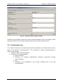
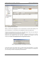
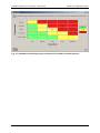
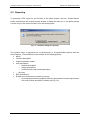
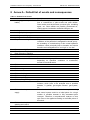
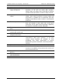
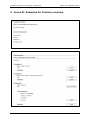
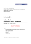
Grant agreement no. EIE/06/078/SI2.447511
Project acronym: Gasification Guide
Full title of the action: Guideline for safe and eco-friendly biomass gasification
Intelligent Energy – Europe (IEE)
Key action: ALTENER
Deliverable D11:
Software Tool
Risk Analyzer - User Manual
Software version, April 2008-04-18
DRAFT VERSION
Author:
Friedrich Lettner, Peter Haselbacher, Helmut Timmerer, Markus Seebacher
Institute of Thermal Engineering
Graz University of Technology
Inffeldgasse 25B
A-8010 Graz
Österreich - Austria
www: www.iwt.tugraz.at
The project is co-funded by the European Commission.
Software Tool RISK ANALYZER (beta) - User manual
EIE-06-078 - Gasification Guide
Table of Contents
Table of Contents .....................................................................................................................2
Foreword ..................................................................................................................................3
1
Software tool RISK ANALYSER ...........................................................................................4
1.1
Objective and target group .......................................................................................4
1.2
Method......................................................................................................................4
1.3
Required preparation and documents by the user (group) .......................................4
2
Installation and system requirements ...............................................................................5
2.1
System requirements................................................................................................5
2.2
Installation procedure ...............................................................................................5
2.3
Start Programme ......................................................................................................6
2.4
Uninstall ....................................................................................................................6
3
General descriptions.........................................................................................................6
3.1
Structure and hierarchy of the implemented database .............................................6
3.2
Reference designation (function and unit codes) .....................................................6
4
Definition of the process and the gasification plant ..........................................................6
4.1
Project selection and management ..........................................................................6
4.2
Definition of process units.........................................................................................8
4.3
Definition of functions for each process unit .............................................................9
4.4
Definition of units (for each function) ......................................................................10
4.5
Definition of design parameters (of units) ...............................................................12
4.6
Definition of auxiliary media (for units)....................................................................13
5
Risk analysis...................................................................................................................14
5.1
Risk analysis window..............................................................................................14
5.2
Definition of frequency and severity parameters ....................................................14
5.3
Definition of events and consequences and risk assessment ................................15
5.4
Countermeasures ...................................................................................................17
6
Summary & Reporting ....................................................................................................20
6.1
Summary (for each function) ..................................................................................20
6.2
Reporting ................................................................................................................21
7
References .....................................................................................................................23
8
Annex A - Default list of events and consequences .......................................................24
9
Annex B - Examples for Function summary ...................................................................27
Revision 1.0
DRAFT VERSION
2/27
Software Tool RISK ANALYZER (beta) - User manual
EIE-06-078 - Gasification Guide
Foreword
The software tool RISK ANALYSER was created in 2007/2008 under the "Gasification Guide"
project, which is supported by the Intelligent Energy for Europe programme under
contract.no. EIE-06-078.
Biomass gasification is a promising technology, which can contribute to the overall EU-policy
to develop future energy systems which are efficient, safe in design and operation as well as
environmental friendly and increase the share of renewable energy. Gasification technology
is near to commercialisation but today large-scale introduction is hampered by various
reasons.
Poor awareness and lack of understanding of the Health, Safety and environment (HSE)
hazards in the project development, planning, design, construction stage and during
operation and maintenance of gasification plants is recognized as a major non-technical
obstacle. The project "Guideline for Safe and Eco-friendly Biomass Gasification" aims to
effectively tackle this barrier.
The objective is to accelerate the market penetration of relatively small scale biomass
gasification systems (< 5 MWFuel) by the development of a Guideline and Software Tool for
easy and simple risk assessment of HSE.
The project homepage can be reached at http://www.gasification-guide.eu.
Legal Disclaimer
The sole responsibility for the content of this report lies with the author. It does not
necessarily reflect the opinion of the European Communities. The European Commission is
not responsible for any use that may be made of the information contained therein.
Whilst every effort has been made to ensure the accuracy of this document, the author
cannot accept and hereby expressly excludes all or any liability and gives no warranty,
covenant or undertaking (whether express or implied) in respect of the fitness for purpose of,
or any error, omission or discrepancy in, this document and reliance on contents hereof is
entirely at the user’s own risk.
Revision 1.0
DRAFT VERSION
3/27
Software Tool RISK ANALYZER (beta) - User manual
EIE-06-078 - Gasification Guide
1 Software tool RISK ANALYSER
1.1 Objective and target group
The generation of the software tool is part of the "Gasification Guide" project (EIE-06-078)
[1], with the objective to accelerate the market penetration of relatively small scale biomass
gasification systems (< 5 MWFuel) for the decentralises energy supply systems based on
renewable sources.
Together with the development of a guideline, the software tool facilitates the assessment of
health, safety and environment (HSE) issues of small scale biomass gasification plants. The
target group of the software tool are in the first place operators, manufacturers, project
developers, researchers, and implementers of biomass gasification plants.
Since the software is created generally open, in order to be used for any gasification
technology and process chain (compare with the “technology description” in the guideline,
also generated in this project), it can moreover also be used for other processes than
biomass gasification.
1.2 Method
From literature there are many possible approaches regarding risk assessment procedures
available [2-4]. The substantial differences between these methods often lie in the basic
approach and the degree of exactness of the reachable results.
Biomass gasification in small and medium scale systems is partly a unique technology where
no explicit techniques and no guidance for the conduction of risk assessment are available.
This software provides a recommended risk assessment procedure, which is practicable and
sufficient for the application in biomass gasification plants. The chosen method bases on a
HAZOP study and is enlarged by additional features which are demanded by the application
in biomass gasification plants. The method for the risk assessment which is implemented in
this software tool is described in detail in other reports of the project and in the draft guideline
as well as in the final guideline later on.
1.3 Required preparation and documents by the user (group)
Risk identification and assessment is a very extensive work, where one needs to be aware of
the process, its behaviour and the risk assessment methodology itself. A general suggestion
is that risk assessment should be done in team-work, since creativity is enhanced and
oversight of possible hazards can be reduced. Prior to starting the software aided risk
assessment the following points should be prepared:
• plant data (process schemes, piping and instrumentation diagram (P&I), plant part
reference designation codes, apparatuses design, etc.)
• predefined plant operation modes (knowledge about start-up, shut-down and normal
operation mode), process control strategies
• desired operation conditions (temperature, pressure, flows and expected gas
compositions)
• machinery lists, details construction drawings
• mass and energy balances, process stream information (composition and pollutant
load)
Revision 1.0
DRAFT VERSION
4/27
Software Tool RISK ANALYZER (beta) - User manual
EIE-06-078 - Gasification Guide
The above process information should reasonable be fed into the software by a single
person, before starting the risk assessment by the team.
2 Installation and system requirements
2.1 System requirements
The software RISK ANALYSER is programmed for the Java runtime environment. Java has to
be installed in order to run RISK ANALYSER.
The system requirements are:
•
•
•
Intel® Pentium® III or equivalent processor
Microsoft® Windows® Vista; Windows XP (or Tablet PC Edition); Microsoft Windows
2000;
512 MB of RAM
Java runtime environment
download Java from: http://www.java.com/en/download/
Since Java is platform independent, the software will be available for all other operating
systems in the future.
2.2 Installation procedure
RISKANALYSER comes with a (multi-language) self-installer (setup.exe), which is shown for
Windows in the following.
Revision 1.0
DRAFT VERSION
5/27
Software Tool RISK ANALYZER (beta) - User manual
EIE-06-078 - Gasification Guide
2.3 Start Programme
The programme Risk Analyser can be started via:
Start → Programs → RiskAnalyser
2.4 Uninstall
The uninstaller can be reached via :
Start → Programs → Uninstall RiskAnalyser
3 General descriptions
3.1 Structure and hierarchy of the implemented database
During the definition of the process and the gasification plant the following hierarchy has to
be used.
1. Process units (top):
2. Functions (of a process unit):
3. Units (needed to fulfil a function, and so belonging to the function):
For better clarity, the whole process has to be divided into process units (e.g. gasifier, or gas
scrubbing). Every process units is subdivided into functions (e.g. cooling of the gas).
Subsequently units (i.e. plant parts) are assigned for each function.
3.2 Reference designation (function and unit codes)
Each process function and unit is designated in the software tool by a code. It is
recommended to use a structured designation system according to latest international
standardisation for power plants, i.e. IEC 61346-1 “Structuring principles and reference
designation”, and the RDS-PP (reference designation system for power plants) respectively
[5, 6].
4 Definition of the process and the gasification plant
4.1 Project selection and management
RISK ANALYSER stores all information (all projects, all default settings, etc.) in one or more
database files.
This file is stored in e.g. <ProgramDirectory>\db and is called e.g. “database”. Any new
project will be saved into the selected database, given on the starting screen.
Revision 1.0
DRAFT VERSION
6/27
Software Tool RISK ANALYZER (beta) - User manual
EIE-06-078 - Gasification Guide
The first screen of RISK ANALYSER allows the management of databases and projects within
a database file (Fig. 1).
The procedure is
1. Create/delete databases: In the background a database will be created or deleted)
2. Select and open a database: The user has to select the wanted data base, via mouse
click and opens the database by selecting “Open database”. The different projects
(maybe different gasification plants) within this data base will be shown in the window
below.
3. Create new project, or open or delete an existing project: When a data base was
activated and open existing project within the data base can be added, opened or
deleted.
Fig. 1: Front Screen: Database and project management
After opening a project (here: “Example_Project”), the basic information of the project and
the evaluated gasification plant can be filled in into the window “Basic Data” (Fig. 2). Data for
manufacturer, operator and the plant power and performance are requested. Data is saved
with the button “Save Data”.
Revision 1.0
DRAFT VERSION
7/27
Software Tool RISK ANALYZER (beta) - User manual
EIE-06-078 - Gasification Guide
Fig. 2: Basic Data of the project and the gasification plant
4.2 Definition of process units
The next step is the definition of process units.
The procedure is
1. Click “Basic Data” in the Project Tree (Left part of the screen).
2. Click “New Process Unit” in the Control area of basic data window (bottom left)
3. Create new process unit.
Each process unit must have a name and a code. The code can be taken e.g. from the
piping and instrumentation diagram for example (P&I diagram).
Revision 1.0
DRAFT VERSION
8/27
Software Tool RISK ANALYZER (beta) - User manual
EIE-06-078 - Gasification Guide
Fig. 3: New process unit
Fig. 4: Example for the definition of process units for a typical gasification plant
A selected function can be deleted by the usage of the delete button.
! Warning: The “Delete-Button” removes the selected data irrecoverable. A undofunction is not implemented. If the foremost process unit is selected and deleted all
sub-items and information will be lost!
4.3 Definition of functions for each process unit
Every process unit is subdivided into functions. To define new functions, the procedure is
1. Click on the respective process unit for which the function should be defined (e.g.
Gas Scrubber) in the project tree
2. Click “New Function” (control area of process unit window - bottom left)
3. Create new function.
4. Assign name and code (at least)
Revision 1.0
DRAFT VERSION
9/27
Software Tool RISK ANALYZER (beta) - User manual
EIE-06-078 - Gasification Guide
5. Press “Save Data”
This is shown for the process unit “Gas Scrubber” in Fig. 5, where the following functions
were defined exemplarily:
• Gas scrubbing and transport
• Scrubbing media circulation
• Scrubbing media treatment
• Scrubbing media recirculation and waste water treatment
Again functions must have a name and a code. For each function a general description is
required as well as a description for the plant operation modes (verbally in the respective text
fields). The operation modes are
• Normal mode,
• Start-up,
• Shut-down,
• Emergency stop.
Fig. 5: Definition of functions for a process unit
4.4 Definition of units (for each function)
Every function consists of units (i.e. plant parts). The defining procedure is
1. Click on the respective function for which the unit should be defined (e.g. “Gas
Scrubbing and Transport”) in the project tree
2. Click “New Unit” (control area of function window - bottom left)
Revision 1.0
DRAFT VERSION
10/27
Software Tool RISK ANALYZER (beta) - User manual
EIE-06-078 - Gasification Guide
3. Create new unit
4. Assign name and code (at least)
5. Press “Save Data”
This is shown for the function “Gas Scrubbing and Transport” in Fig. 6, where the following
units were defined exemplarily:
• Quench
• Scrubber Tank
• Packing material
• Scrubbing column
Fig. 6: Definition of units for the function “Gas Scrubbing and Transport” (exemplarily)
Again units must have a name and a code. Units can be assigned with design parameters
and auxiliary media (solid, liquid, and gaseous). Exemplarily, these data for unit “Quench”
are shown in Fig. 6 as well:
Design parameter for unit “quench”, e.g. temperature: Min: 75°C, Normal: 90°C, Max: 120°C.
Auxiliary media:
Liquid: scrubbing water
Gaseous: producer gas after fabric filter (after process unit de-dusting)
Revision 1.0
DRAFT VERSION
11/27
Software Tool RISK ANALYZER (beta) - User manual
EIE-06-078 - Gasification Guide
4.5 Definition of design parameters (of units)
The user can define an unlimited number of design parameter for each unit (plant part). By
default there is a list of typical design parameters (temperature, pressure, pressure drop, tar
and particle load in the producer gas) to choose from. Any other design parameters can be
added by the user as necessary by pressing the button “Add design parameter”.
Fig. 7 shows the dialog window for the creation and assignment of design parameters. The
procedure is as follows:
1. Creation of a new parameter at the fields to the right
(e.g. Description: Water content producer gas, and Unit: vol% H2O_dry basis).
Pressing “create new design parameters” will add the new parameter to the list of
default design parameters at the left
2. Selection of a design parameter in the list
3. By pressing the “Add”-Button, the parameter will be added to the Unit window
4. Apply Min/Norm/Max values to your parameter
Design parameters can easily be imported from existing settings done for other units (Button:
“Import parameter from unit” in the unit window).
Deleting of parameters can be done via the “delete”-button.
! Warning: The “Delete-Button” removes the selected data irrecoverable. A undofunction is not implemented!
Fig. 7: Definition of design parameters (for units / plant parts)
Revision 1.0
DRAFT VERSION
12/27
Software Tool RISK ANALYZER (beta) - User manual
EIE-06-078 - Gasification Guide
4.6 Definition of auxiliary media (for units)
The user can define an unlimited number of auxiliary (solid, liquid, and gaseous) media (i.e.
process streams) for each unit (plant part) and assign parameters to them. Any process
streams can be added by the user as necessary by pressing the button “Add
Medium/Parameter”.
Fig. 8 shows the dialog window for the creation and assignment of auxiliary media for units.
Streams can be assigned with parameters in the following way:
1. Selection of a media from the drop-down list
2. Selection of a media parameter in the list
3. By pressing the “Add Parameter”-Button, the parameter will be added to the media
parameter list in the bottom of the screen (hence to the selected media)
4. New parameters can be created in the fields to the right (description and unit), and
pressing the ◄-button will add them to the media parameters list (left)
5. Alternatively media parameters can be deleted by the ►-button
Fig. 8: Definition of auxiliary media streams (for units / plant parts)
After closing the window the user returns to the unit window. Here media parameters can
easily be imported including their properties (media parameters) from existing settings done
for other units (Button: “Import auxiliary media from unit” in the unit window). Deleting of
parameters can be done via the “delete parameter”-button.
! Warning: The “Delete-Button” removes the selected data irrecoverable. An undofunction is not implemented!
Revision 1.0
DRAFT VERSION
13/27
Software Tool RISK ANALYZER (beta) - User manual
EIE-06-078 - Gasification Guide
5 Risk analysis
5.1 Risk analysis window
Fig. 9 shows the risk assessment window. Risk assessment has to be applied for each
process function (here: gas scrubbing and transport), which is selected in the project tree
(left). In the upper part of the window a list of all parts which belong to the selected function is
shown.
In the lower part of the window lists for events and consequences can be created. The
default database contains a list of 36 events and 17 preset consequences, which can be
extended by each user as necessary. These two lists can be found in Annex A to this manual
(Table I and Table II).
Fig. 9: The risk assessment window
5.2 Definition of frequency and severity parameters
In the lower left part of the risk assessment window, you can look at the currently used
frequency and severity parameters. You may also adjust them to your needs. These
parameters are defined for your whole project and will be used in your RiskMatrix and the
final report you create.
Revision 1.0
DRAFT VERSION
14/27
Software Tool RISK ANALYZER (beta) - User manual
EIE-06-078 - Gasification Guide
5.3 Definition of events and consequences and risk assessment
The user can define an unlimited number of events and consequences with the fields “New
events” and “new consequences” respectively.
The ▲ - button residing left to the “New event”\”New Consequence” text field will add the
new event/consequence to the list, the ▼ will delete a marked event\consequence from the
list.
The next step is the combination of all possible events in the respective process function with
possible consequences. The procedure is indicated in Fig. 10 and explained in the following:
1. Select the event you want to add by clicking on it
2. Select the consequences you want to add to the event by clicking the checkboxes in
the consequences window
3. By pressing the ▼ - Button in the ‘Add and Delete Events and Consequences’ group
you add them to the Risk Assessment
4. When the combination is selected (blue background) it can be evaluated with a risk:
5. Selection of a probability (slide bar)
6. Selection a severity (slide bar)
7. Save - Button
1
2
3
Fig. 10: Definition of events and consequences
Revision 1.0
DRAFT VERSION
15/27
Software Tool RISK ANALYZER (beta) - User manual
EIE-06-078 - Gasification Guide
According to the combination of probability (i.e. frequency) and severity a risk is associated
to each pair of event and consequence. The risk can be “ok”, “alarp” or “unacceptable”. Alarp
stands for “as low as reasonable possible”. The implemented risk matrix is shown in Fig. 11.
Unacceptable risks have to be removed by a countermeasure. Other risks may also be
lowered by counter measures.
If a counter measure will be set, the shield-symbol has to be activated in the CM (y/n)
column. For unacceptable risks this is activated obligatory.
As long as there are unacceptable risks within a process function, no summary can be
created.
Frequency
frequent
1
probable
A
casual
2
imaginable
3
improbable
B
unthinkable
inessential
marginally
critical
disastrous
Effects / Severity
acceptable region
ALARP region (As Low As Reasonably Practicable Region)
unacceptable region
Fig. 11: Risk matrix of frequency vs. severity
During risk assessment, changes in the plant operation may be necessary. These adoption
can be described in the “Change operation modes”-window (see Fig. 12), which can be
accessed from the risk assessment window. On the left side, you will find your original
operating modes. On the right side, you can define new operating modes. If you want to copy
one original mode to the right side, click into the mode and press the “Copy” button.
Revision 1.0
DRAFT VERSION
16/27
Software Tool RISK ANALYZER (beta) - User manual
EIE-06-078 - Gasification Guide
Fig. 12: “Change operation modes”-window
Changes in the operation mode will be part of the documentation of the risk analysis, which
will be generated at the summary-window (project tree) for each process function.
5.4 Countermeasures
For all pairs of events and consequences that were assigned for, countermeasures can be
taken in the window “Countermeasures”. The procedure of setting countermeasures is
shown in the following:
1. Selection of the event/consequence
2. Creation of the countermeasure:
a. Name (text field)
b. Selection of a category (organizational, technical, constructive, process
control strategy)
c. Add
d. Changing of the probability or the severity (lowering) due to the new
countermeasure
Revision 1.0
DRAFT VERSION
17/27
Software Tool RISK ANALYZER (beta) - User manual
EIE-06-078 - Gasification Guide
Fig. 13: Setting of countermeasures
When you select one consequence or one countermeasure, all items which belong to the
same consequence or countermeasure are highlighted to show their togetherness.
Technical countermeasures may involve new units (plant parts). These units can easily be
created at the bottom of the “countermeasures”-window.
At the end of the risk assessment, when you enter the “Summary” window the user is asked,
whether the new assigned units have also been considered and evaluated in the risk
analysis (see Fehler! Verweisquelle konnte nicht gefunden werden.).
Fig. 14: Question dialog for consideration of new units
In the lower left part of the window, there is a button called “Show Risk Matrix”. If you press
this button another window opens and displays the connection between the consequence
you are working on and the corresponding countermeasures.
Revision 1.0
DRAFT VERSION
18/27
Software Tool RISK ANALYZER (beta) - User manual
EIE-06-078 - Gasification Guide
Fig. 15: Risk Matrix containing selected consequence and added countermeassures
Revision 1.0
DRAFT VERSION
19/27
Software Tool RISK ANALYZER (beta) - User manual
EIE-06-078 - Gasification Guide
6 Summary & Reporting
6.1 Summary (for each function)
Summaries are created on a per function basis. When you enter the window, first the
program checks if you have rated all your consequences and countermeasures and if you
considered all you newly created parts (in the countermeasures – window). In the upper part
of the window, you see your original operating modes, the consequences with their risks and
a list of all countermeasures you created. Again operating modes (new after changes
through risk analysis) can be edited, this is done in the lower part of the window.
Fig. 16: Function Summary
Revision 1.0
DRAFT VERSION
20/27
Software Tool RISK ANALYZER (beta) - User manual
EIE-06-078 - Gasification Guide
6.2 Reporting
To generate a PDF report for you function or the whole project, click the “Create Report”
button at the bottom left of the summary window. A dialog box asks you, if you prefer printing
a report only for the current function or for the whole project.
Fig. 17: Selection dialog for reporting
The function report is generated as a pdf-document in <ProgramFolder>\reports with the
name Reports_<FunctionName> and consists of the following points:
• Name
• Function description
• Original operation modes
• Unit descriptions
o General description
o Design parameters
o Auxiliary media (with media parameter)
• … (all units)
• Risk Assessment
• Events and consequences (sorted by events)
o If countermeasures were applied, these are documented and the improvement
of the risk (before and after) is shown (see Fig. 18).
Revision 1.0
DRAFT VERSION
21/27
Software Tool RISK ANALYZER (beta) - User manual
EIE-06-078 - Gasification Guide
Fig. 18: Reporting of Risk assessment with countermeasures applied
If you chose to create a complete report, additional to all the function reports, the file also
includes your project’s basic data, your process units and the frequency and severity
parameters you created. It is also located in <ProgramFolder>\reports with
Report_<ProjectName> as filename.
Revision 1.0
DRAFT VERSION
22/27
Software Tool RISK ANALYZER (beta) - User manual
EIE-06-078 - Gasification Guide
7 References
[1]
[2]
[3]
[4]
[5]
[6]
"Gasification Guide", Guideline for safe and eco-friendly biomass gasification, project
no. EIE-06-078, www.gasification-guide.eu, in process.
Steinbach J, Antelmann O, Lambert M: Methoden zur Bewertung des
Gefahrenpotentials von verfahrenstechnischen Anlagen, Schriftenreihe der
Bundesanstalt für Arbeitssschutz und Arbeitsmedizin, Berlin-Dortmund, 1991.
Steen H: Handbuch des Explosionsschutzes, Wiley-VCH, Willingdon/England, 2000.
Kühnreich K, Bock F-J, Hitzbleck R, Kopp H, Roller U, Woizischke N: Ermittlung und
Bewertung des Gefahrenpotentials für Beschäftigte in verfahrenstechnischen
Anlagen und Lagereinrichtungen, Berlin-Dortmund, 1998.
DIN 6779-10, Kennzeichnungssystematik für technische Produkte und technische
Produktdokumentation - Teil 10: Kraftwerke, 2007-04.
EN 61346-1, Industrial systems, installations and equipment and industrial products.
Structuring principles and reference designations. Part 1: Basic Rules, 1998-01-14.
Revision 1.0
DRAFT VERSION
23/27
Software Tool RISK ANALYZER (beta) - User manual
EIE-06-078 - Gasification Guide
8 Annex A - Default list of events and consequences
Table I: Default list of events
i
name
1
Leakage (gas escape / air
intake)
2
3
4
5
6
Leakage steam
Leakage liquids (escape)
Leakage scrubbing agents
Leakage solids
Temperature too high/low
7
8
9
10
11
Pressure too high/low
Plant flows too high/low
Plant fill level too high/low
Concentration too high/low
Failure - mechanical stress
12
13
14
15
16
17
18
19
20
Failure - thermal stress
Failure - corrosion
Failure - icing
Failure - ware out
Failure - blocking
Failure - sealing
Failure - welding
Failure - fitting or flange
Hot surfaces
21
Failure - electric power
supply
22
Failure - electric plant
steering and control
Failure - electrical device
Failure - sensor
23
24
Revision 1.0
description
The term leakages includes the types of unpredictable
loss of containment of plant media and plant utilities.
Plant media could be biomass, producer gas, scrubbing
agent, etc. Plant utilities are possibly pressurised air,
cooling agents, inertisation media like nitrogen, etc.
Physical/chemical parameters gives defined operation
conditions of the particular investigated functional group an exceeding or undershooting of this normal operation
conditions could principally lead to hazards and should
therefore be investigated as for "too high" or "too low".
Part or functional group failure can have various shape,
depending on operation conditions or mechanical,
thermal or chemical stress.
Thermal conversion plants possess system immanent hot
surfaces, which have to be analysed due to possible
hazards, f.i. gasifier, gas engine exhaust gas system,
etc.
Failure in electrical installations, devices or plant steering
and control system could be a initial points for a huge
number of possible hazards in fully automated plant
concepts. Therefore a comprehensive analyse on that
topic have to be applied according to the listed points of
this rubric.
DRAFT VERSION
24/27
Software Tool RISK ANALYZER (beta) - User manual
i
25
name
Failure - plant media/utility
supply and disposal
26
Harmful plant media and
utilities
27
Transient operation - start-up
28
31
Transient operation - shutdown
Transient operation increase plant power load
Transient operation emergency shut-down
Operating error
32
33
Maintenance
Force of nature - flooding
34
Force of nature - stroke of
lightning
Force of nature storm/thunderstorm
Force of nature - earthquake
29
30
35
36
Revision 1.0
EIE-06-078 - Gasification Guide
description
The reliable supply with plant medias and plant utilities is
necessary for the safe and stable plant operation.
Failures within the supply chain could lead to transient
operation states (shut down) or failure of safety functions.
Biomass Gasification plants process different medias and
utilities, which could be harmful for human health and
environment. A possible loss of containment (see also
leakage) could directly result in health or environmental
impairment.
Transient plant operation states includes start-up, shut
down and changes of plant power load, where grave
intervention into the plant control parameters, applied by
the operator or automatic routines, take place.
Operating error are frequent reasons for hazardous
consequences within plant operation, so the plant
concept should therefore be analysed on such
possibilities and further improvement to prevent
maloperation (process automation, technical precaution fail-safe)
Forces of nature have generally to be considered and
focuses on the reliability of the process chain under such
environmental influences.
DRAFT VERSION
25/27
Software Tool RISK ANALYZER (beta) - User manual
EIE-06-078 - Gasification Guide
Table II: Default list of consequences
i
name
description
1
Abnormal operation
Abnormal operation conditions are typically described by
conditions
exceeding/undershooting of normal operation conditions
and physical/chemical media properties and can have
various reason.
2
Mechanic failure
This term contains various types of possible failure and
failure reasons - see also event list.
3
Danger from electricity
Danger from electricity includes hazards, where electrical
installation and their possible malfunctions are involved.
4
Failure gas engine /
Biomass conversion plants (gasification, combustion)
Emergency stop
process solid, liquid and/or gaseous fuels and have to
guarantee a safe utilisation of varying feedstock and
under different plant operation states (normal operation,
start up, shut down, etc.)
5
Failure of combustion system
6
Failure of flare / Emergency
gas utilisation
7
Failure of automation system The stable operation of the automation system assume a
functioning process electric system; f.i.: unpredictable
failure from plant sensor could lead to an total or partwise failure of the automation system.
8
Danger to health
Possible dangers to health and impact on environment
are summarised within this rubric.
9
Danger to health - skin burns
10 Danger to health - irritation of
skin mucous membrane
11 Noise pollution, ototoxic
noise
12 Immission (exhaust, flue gas
and smell/odour)
13 Poisoning
14 Smouldering fire
Fire and explosion are, apart from danger to health or
environment, consequences with an almost always high
severity. This type of consequence requires in most of
cases counter measures and an extended safety concept
for successful risk reduction - see risk assessment.
15 Fire
16 Explosion
17 Failure of function
Functions failure means the occurance of and specific
function of the investigated unit or sub unit, which leads
to fatal errors in the process chain.
18 others
Revision 1.0
DRAFT VERSION
26/27
Software Tool RISK ANALYZER (beta) - User manual
EIE-06-078 - Gasification Guide
9 Annex B - Examples for Function summary
Revision 1.0
DRAFT VERSION
27/27