1
Wifi Shield V2.0
Overview
This WiFi shield features the RN171 TCP/IP module to allow your Arduino/Seeeduino to
connect with up to 802.11b/g wireless networks.
The shield's default communication protocol with the Arduino is UART/Serial, and you may
select which digital pins (D0 to D7) to use for RX and TX with two jumper rows we've
incorporated. The shield also has two on-board Grove connectors for I2C and Serial to allow the
shield to be used with any of our Grove devices.
An on-board antenna allows the shield to cover a wider range and transmit stronger signals. The
RN171 module supports TCP, UDP, FTP, and HTTP communication protocols to meet the needs
of most wireless and Internet of Things (IoT) network projects e.g. smart home networks, robots
control, personal weather stations.
The shield is very well documented with our examples below and its user manual.
Specification
Operate voltage
3.3~5.5 V
Compatible board directly
Arduino Uno/Seeeduino
Current
25~400mA
Transmit power
0-10 dBm
Frequency
2402~2480 MHz
Channal
0~13
Network rate
1-11 Mbps for 802.11b/6-54Mbps for 802.11g
Dimension
60X56X19 mm
Net Weight
24±1 g
Secure WiFi authentication
WEP-128, WPA-PSK (TKIP), WPA2-PSK (AES)
Built-in networking
applications
DHCP client, DNS client, ARP, ICMP ping, FTP, TELNET, HTTP, UDP, TCP
Certification
RN171 : FCC, CE
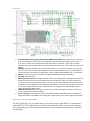
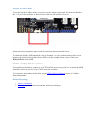
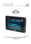
Shield Interface and Components
The WiFi shield is compatible with any Arduino/Seeeduino development board as it only
requires two digital pins of your choice between D0-D7 for UART/serial communication. To
install, simply stack the shield on the Arduino/Seeeduino board.
Overview
1. Serial Peripheral Interface (SPI) Connections (MOSI, SCK, MISO): These pins are not connected
to any of the Arduino's pins, they are independent and the logic level output/input of them is
3.3V. They can be used to communicate with the Arduino via SPI but a 3.3V logic converter
between these pins and the Arduino's will be needed. The data rate in SPI mode can reach up to
2Mbps.
RES_Wifi: The Wifi shield has an on-board "Rest Button" for the RN-171 module, you may also
reset the RN-171 via software by sending the reset command. Additionally, if you would like to
connect this pin to the Arduino's digital 6 pin, simply solder the pad labeled "P5" on the shield.
2. RN171: a super low power consumption wireless module with TCP/IP stack built in.
3. Antenna: I.PEX connector.
4. RN171 breakout section: The RN171 module has its own analog input and GPIO pins, which the
shield provides access to via this breakout section. The GPIO pins (IO3, IO7, IO8, and IO9) are
3.3V tolerant while the analog input pins (S_0 and S_1) can read 0-400mV (Do not exceed 1.2V).
The RN171 can be configured to use these pins by software or they may connected to other pins
to use other RN171 functions such as adhoc mode. The voltage of VCC is dependent on the
supply power of the WiFi shield.
5. UART/Serial Select area: Two jumper rows to let you select which RX and TX pins you want to
use to communicate with the Arduino.
6. Grove connectors: Analog I2C Grove (if using Arduino UNO or Seeeduino) for pins A4&A5 and
Digital Serial Grove for D8&D9. The voltage VCC is dependent on the power supply of the board.
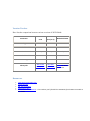
Pins Used / Shield Compatibility
The WiFi shield uses any two digital pins of your choice between D0 and D7 to communicate
with the RN171 WiFi module, however keep in mind that D0 and D1 are used by the Arduino
for programming and serial communication purposes and using them might interfere with these
two functions.
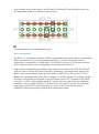
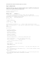
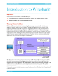
In the example codes in this page we use D2 and D3 as RX and TX for the shield. In this case,
the jumper hats should be connected as shown below:
D2 selected for WIFI_TX, D3 selected for WIFI_RX
RN171 WiFi Module
The RN-171 is a standalone complete TCP/IP wireless networking module. Due to its small form
factor and extremely low power consumption, the RN-171 is perfect for mobile wireless
applications. It incorporates a 2.4GHz radio, 32-bit SPARC processor, TCP/IP stack, real-time
clock, crypto accelerator, power management, and analog sensor interfaces.
In the simplest configuration the hardware only requires four connections (PWR, TX, RX and
GND) to create a wireless WiFi data connection. Additionally, the analog sensor inputs of the
RN171 can be used as analog input pins, their rating is 0-400 mV (Do not exceed 1.2V DC).
Power: The operating voltage of the RN-171 module is 3.3VDC typically, so a voltage regulator
and logic level translator are designed on the WiFi shield. The LD1117 regulator on the shield
converts to 3.3VDC, which supplies the RN171 module. However, due to the auto judgement
schematic of power supply, the RN-171 can be powered via both 3V3 pin and 5V pin. But the
supply power would be 5v if providing both 3.3v and 5v to the board. If using with an
Arduino/Seeeduino board simply stack the WiFi shield on the board.
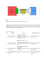
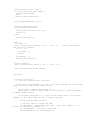
Diagram of how the RN171 module is interfaced to the Arduino
GPIO_6 : The GPIO6 pin of the RN171 WiFi module is by default only connected to the LED
labeled D5 on the WiFi shield. This LED is used to display the status of the Access Point (AP)
connection. If however, you would like to connect GPIO6 to digital pin 5 of the Arduino, simply
solder the pad labeled "P6" on the WiFi shield.
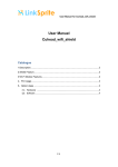
LED Status Indicators
Label
D5
Description
Green LED. Indicates the
association status.
Status
OFF: means the module is not
associated with a network.
Solid ON: indicates that it is associated
and Internet access is OK
Hardware Connection
Connected to GPIO6 of the
RN171 module
Solid ON: connected over TCP.
D1
Fast Toggle (2 times/second): No IP Connected to GPIO4 of the
Red LED. Indicates the
address or module is in command
TCP/IP connection status.
mode.
RN171 module
Slow Toggle (once/second): IP
address is OK.
RST
Red LED. WiFi module
reset status.
Solid ON: The reset button (WIFI_RST) is Connected to Reset of the
been pressed.
RN171 module.
Green LED. Indicates WiFi
Connected to the 3.3V output
Solid ON:The module/shield is powered
of the LD1117 voltage
PWR module's power up
up.
status.
regulator.
WiFi Library
We have created a library to help you interface with the shield, in this section we'll show you
how to set up the library and introduce some of the functions.
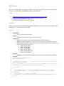
Setup
1.
2.
3.
4.
Download the library code as a zip file from the Wifi Shield github page.
Unzip the downloaded file into your …/arduino/libraries/ folder .
Rename the unzipped folder "WifiShield"
Start the Arduino IDE (or restart if it is open).
Functions
These are the most important/useful function in the library, we invite you to look at the .h files
yourself to see all the functions available.
join()
Description:
Used to join a WiFi access point
Syntax:
join(const char *ssid, const char *phrase, int auth)
Parameters:
ssid: The name of the access point you want the shield to connect to
phrase: The password/phrase of the access point you want the shield to connect to
auth: The authentication type of the access point you want the shield to connect to. Can
be one of the following constants:
WIFLY_AUTH_OPEN
WIFLY_AUTH_WEP
WIFLY_AUTH_WPA1
WIFLY_AUTH_WPA1_2
WIFLY_AUTH_WPA2_PSK
WIFLY_AUTH_ADHOC
Returns:
boolean: true if the connection to the access point was successful, false otherwise.
Example:
#include <SoftwareSerial.h>
#include "WiFly.h"
SoftwareSerial uart(2, 3); // create a serial connection to the WiFi
shield TX and RX pins.
WiFly wifly(&uart); // create a WiFly library object using the serial
connection to the WiFi shield we created above.
void setup()
{
uart.begin(9600); // start the serial connection to the shield
Serial.begin(9600); // start the Arduino serial monitor window
connection
wifly.reset(); // reset the shield
while(wifly.join("mySSID","mySSIDpassword",WIFLY_AUTH_WPA2_PSK) ==
false)
{
Serial.println("Failed to connect to accesspoint. Will try
again.");
}
Serial.println("Connected to access point!");
}
void loop()
{
}
receive()
Description:
o Can be used to read data from the shield, an alternative for the Arduino's read()
function.
Syntax:
o receive(uint8_t *buf, int len, int timeout)
Parameters:
o buf: A buffer array where the bytes read from the shield is stored.
o len: The length/size of the buffer array
o timeout: A timeout value to know when to stop trying to read.
Returns:
o int: The number of bytes read from the shield.
Example:
char c;
while (wifly.receive((uint8_t *)&c, 1, 300) > 0) {
Serial.print((char)c);
}
See File->Examples->WiFi_Shield->wifly_test sketch for a complete example.
sendCommand()
Description:
o Some our functions (e.g. join(), reboot(), save()) act as wrappers for the text commands
listed in the user manual of the RN171 module. The function sendCommand() allows
you to come up with your own wrapper function if ours do not meet your needs.
Syntax:
o sendCommand(const char *cmd, const char *ack, int timeout)
Parameters:
o cmd: Any command from the RN-171's user manual.
o ack: The expected return string from the command
o timeout: The time allowed before considering the output a bad request/response
Returns:
o boolean: true if the WiFi shield responded with the ack string, false otherwise.
Example:
// our join() function is wrapper for the join command, as seen below.
//The string "Associated" is what the user manual says the RN171 will
return on success.
if(sendCommand("join\r", "Associated",DEFAULT_WAIT_RESPONSE_TIME*10))
{
// joined
}else{
// not able to join
}
See File->Examples->WiFi_Shield->wifly_test sketch for a complete example.
WiFi Shield Examples/Applications
Example 1: Send Commands to WiFi Shield and Receive Response Via The Arduino Serial
Monitor Window
The WiFi shield's RN-171 module is configured by sending it the commands found in its
datasheet. You may write a sketch to send the commands automatically, but this is a great
example that we recommend you go through because it will teach you exactly how the WiFi
shield and RN-171 works.
To proceed follow the steps below, we have also created a video if you prefer to watch that
Video - Getting Started With Seeeduino's WiFi Shield.
Step 1: WiFi Shield Jumpers Configuration
Position the jumpers in the WiFi shield such that digital pin 2 (D2) is selected for WIFI_TX, and
digital pin 3 (D3) is selected for WIFI_RX as shown in the photo below. These are the pins we
will use to send and receive information from the RN-171.
Pins D2 for TX, and D3 for RX
Step 2: Software/Code
In the sketch below we have created a UART object to allow us to send and receive data from
the RN-171/WiFi Shield. We then use this object in conjunction with the WiFly library to send
data to the shield. The Arduino's Serial object is used to print the data we receive from the shield,
and to receive the commands we want to send to the shield via the WiFly/UART object.
Upload the following code to your Arduino board:
#include <Arduino.h>
#include <SoftwareSerial.h>
#include "WiFly.h"
// set up a new serial port.
SoftwareSerial uart(2, 3); // create a serial connection to the WiFi shield
TX and RX pins.
WiFly wifly(&uart); // create a WiFly library object using the serial
connection to the WiFi shield we created above.
void setup()
{
uart.begin(9600); // start the serial connection to the shield
Serial.begin(9600); // start the Arduino serial monitor window connection
delay(3000); // wait 3 second to allow the serial/uart object to start
}
void loop()
{
while (wifly.available()) // if there is data available from the shield
{
Serial.write(wifly.read()); // display the data in the Serial monitor
window.
}
while (Serial.available()) // if we typed a command
{
wifly.write(Serial.read()); // send the command to the WiFi shield.
}
}
Step 3: Entering Command Mode
The WiFly RN-171 module in the WiFi shield can operate in two modes: data, and command.
When in data mode, the shield is able to receive and initiate connections. When in command
mode, we are able to configure the module using the commands listed in its datasheet.
To enter command mode, follow these steps:
1.
2.
3.
4.
Open the Arduino Serial monitor.
Set the serial monitor to “No line ending”, baud rate to 9600.
Type "$$$" into the Arduino Serial Monitor and press enter.
The module will respond with the letters “CMD”, indicating that it has entered command mode.
Let's go ahead and test some commands, do the following:
1. In the Arduino Serial monitor window, select “Carriage return” and a baud rate of 9600.
2. Now type each of the commands in the table below into the Arduino Serial Monitor and press
enter.
3. The module will output a response, as described in the table, for each command.
Commands
Description
scan
This command performs an active probe scan of access points on all 13 channels.
When you use this command, the module returns the MAC address, signal strength,
SSID name, and security mode of the access points it finds.
get ip
This command displays the IP address and port number settings
For a complete list of configuration commands, please see the RN-171 Reference Guide starting
on page 11.
Example 2: Connect to An Access Point / Internet Router
In this example we will show you how to connect the WiFi shield to an access point (your
internet router) with and without you typing the commands required:
Connecting By Typing Commands
This section will teach you how to connect the WiFi shield to an access point using commands
from the RN-171 datasheet, by going through this section you will then know exactly what is
happening in the background when you use our WiFi Arduino libraries.
Do the following:
1. Upload the code in Example One to your Arduino board
2. Enter command mode:
1. Set the serial monitor to “No line ending”, baud rate to 9600.
2. Type $$$ into the Arduino Serial Monitor and press enter.
3. Set the serial monitor to “Carriage return”.
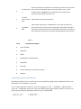
4. Scan for available access points:
1. Type scan and press enter. The Arduino serial monitor window will output a list of
comma separated values for each access point the WiFi shield has found. From left to
right the third value is the security mode, the last value is the SSID. This example shows
a security mode of 4 with an SSID name MySSID: 01,01,88,04,1104,1c,00,45:56:78:be:93:1f,MySSID
5. From the list of access points found, find the one which corresponds to your internet router and
note the security mode, and SSID as we will need these two values to connect to it.
6. Set the security mode in the shield:
1. Type set wlan auth m. Replace m with the security mode number (in this example that
would be 4) of the access point you wish to connect to.
2. The security modes supported by the WiFi shield are listed in Figure 1 below.
7. Set the access point phrase
1. Type set wlan phrase myPhrase. Replace myPhrase with your access point's
password/security key. Note: if your access point's security type is WEP use key instead
of phrase in the command above.
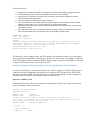
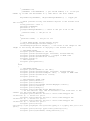
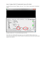
2. The access point's (internet router) phrase is the password you use to connect to it from
your PC. In Windows you can find it as shown in the animated image below:
How to find a networks' security key/password
8. Join the access point
1. Now that we have set the security type and phrase of the access point, we may connect
to it.
2. Type join MySSID. Replace MySSID with your access point's broadcast name.
3. The word "Associated!" will be displayed in the Arduino serial monitor window if
successful.
A description of the commands you entered in the steps above is available in the table below. A
more detailed description of each command can be found in the RN171's user manual.
Number Commands
1
scan
Description
This command performs an active probe scan of access points on all 13
channels. When you use this command, the module returns the MAC
address, signal strength, SSID name, and security mode of the access
points it finds.
2
Find the value that corresponds to the security protocol on your access
set wlan auth point. Then, tell the WiFly what security protocol to use, it is the
number shown in Fijure 1 that corresponds to the access point's
4
security protocol. Here we choose “4”.
3
set wlan
phrase seeed- Tell the WiFi shield your passphrase.
mkt
4
join SEEEDMKT
Tell the WiFi shield to join, “SEEED-MKT“ is the name of the access
point we choose to connect. After sending the command the module
should now connect and print out information about the connection. (If
the connection is failed, try to send the command again until it works )
Figure 1
Value
Authentication Mode
0
Open (Default)
1
WEP-128
2
WPA1
3
Mixed WPA1 and WPA2-PSK
4
WPA2-PSK
5
Not used
6
AD hoc mode (join any ad hoc network)
8
WPE-64
Connecting Using Our WiFi Libraries
Now that you know how to connect to an access point by typing each command it's time to use
the libraries and examples we provide.
To see code required to connect to an access point go to “File -> Examples -> Wifi_Shield ->
wifi_test”. Change the code to use your own SSID (access point name), and KEY (your access
point's password), then upload the sketch to your Arduino IDE.
#define SSID
#define KEY
" SEEED-MKT "
" seeed-mkt "
With the sketch uploaded to your Arduino board, open the serial monitor window. If the shield
was successful in joining the access point an "OK" message will be displayed along with the
connection information resulting from the "get everything" command. If the shield failed to join
the access point a "Failed" message will be displayed.
Configuring The Shield to Connect On Power-Up
The shield can be configured to connect on power up, you only have to do this once:
1. Send the "set wlan ssid mySSID" command replacing mySSID with your SSID
2. Send the "set wlan join 1" command.
3. Send the "save" command.
Now the shield will connect to the access point automatically on power up.
A description of what each command does can be found in the RN-171 datasheet and in the table
below.
Number
Commands
Description
1
set wlan ssid
<ssid>
"<ssid>" is the name of the access point you'd like to connect to
automatically
2
set wlan join 1
This tells the module to try and connect to the SSID stored in
memory automatically.
3
save
Store/Save these settings in the Wifi's config file
Setting a Static IP Address
To have the shield obtain a static IP address from the access point, once connected to the access
point, send the following commands:
Number
Commands
Description
1
set ip dhcp 0
Turn of DHCP .
2
set ip address <address> Set the IP address you want .
Example 3: Communicating With the Network (Introduction)
This example will show you how a device such as your PC and/or phone may talk to the WiFi
shield.
Follow these steps:
1. Configure the module with step1-7 in Example 2's section Connecting By Typing Commands
2. Set the listening IP port to "80" by sending the commands "set ip local 80"
3. Connect/Join your shield to an access point as shown in the step 8 in Example 2's section
Connecting By Typing Commands
4. Save these setting by sending the "save" command
5. Get the IP address of your shield with the command "get ip". The IP address and port will be
displayed to the right of "IP=" in the response (e.g. IP=192.168.0.10:80)
6. Open your web browser and type your shield's IP address in your web browser's URL bar and
press Enter to visit it.
7. Your Arduino's serial monitor window will display an HTTP response similar to the one below.
This is the information that your browser sent to the shield to request data.
*OPEN*GET / HTTP/1.1
Host: 192.168.0.10
Connection: keep-alive
Accept:
text/html,application/xhtml+xml,application/xml;q=0.9,image/webp,*/*;q=0.8
User-Agent: Mozilla/5.0 (Windows NT 6.1; WOW64) AppleWebKit/537.36 (KHTML,
like Gecko) Chrome/39.0.2171.95 Safari/537.36
Accept-Encoding: gzip, deflate, sdch
Accept-Language: en-US,en;q=0.8
The browser is now waiting for data, the Wifi module can send sensor values, serve web pages,
or any other data straight back to the browser! In this case, the browser is waiting for a web page.
If the Wifi module responds with an HTML-formatted page, the browser will display it. The next
examples will teach you how to do all this fun stuff.
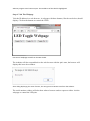
Example 4: Using the WiFi Shield as Webserver (Serving Webpages From the Shield)
As you saw in Example 3, an internet/web browser is able to connect to the WiFi shield. Once a
connection has been established (when the browser sends its HTTP request), the WiFi shield
may then send back HTML code for the browser to display as a webpage. In this example you
will learn what is needed for the shield to reply to a web browser.
Step One: Arduino Code
Upload the following code to your Arduino board replacing "myssid" and "mypassword" with
your accesspoint's values respectively:
#include <SoftwareSerial.h>
#include "WiFly.h"
#define SSID
"myssid"
#define KEY
"mypassword"
// check your access point's security mode, mine was WPA20-PSK
// if yours is different you'll need to change the AUTH constant, see the
file WiFly.h for avalable security codes
#define AUTH
WIFLY_AUTH_WPA2_PSK
int flag = 0;
// Pins' connection
// Arduino
WiFly
//
//
2
3
<---->
<---->
TX
RX
SoftwareSerial wiflyUart(2, 3); // create a WiFi shield serial object
WiFly wifly(&wiflyUart); // pass the wifi siheld serial object to the WiFly
class
void setup()
{
wiflyUart.begin(9600); // start wifi shield uart port
Serial.begin(9600); // start the arduino serial port
Serial.println("--------- WIFLY Webserver --------");
// wait for initilization of wifly
delay(1000);
wifly.reset(); // reset the shield
delay(1000);
//set WiFly params
wifly.sendCommand("set ip local 80\r"); // set the local comm port to 80
delay(100);
wifly.sendCommand("set comm remote 0\r"); // do not send a default string
when a connection opens
delay(100);
wifly.sendCommand("set comm open *OPEN*\r"); // set the string that the
wifi shield will output when a connection is opened
delay(100);
Serial.println("Join " SSID );
if (wifly.join(SSID, KEY, AUTH)) {
Serial.println("OK");
} else {
Serial.println("Failed");
}
wifly.sendCommand("get ip\r");
char c;
while (wifly.receive((uint8_t *)&c, 1, 300) > 0) { // print the response
from the get ip command
Serial.print((char)c);
}
Serial.println("Web server ready");
}
void loop()
{
if(wifly.available())
{ // the wifi shield has data available
if(wiflyUart.find("*OPEN*")) // see if the data available is from an open
connection by looking for the *OPEN* string
{
Serial.println("New Browser Request!");
delay(1000); // delay enough time for the browser to complete sending
its HTTP request string
// send HTTP header
wiflyUart.println("HTTP/1.1 200 OK");
wiflyUart.println("Content-Type: text/html; charset=UTF-8");
wiflyUart.println("Content-Length: 244"); // length of HTML code
wiflyUart.println("Connection: close");
wiflyUart.println();
// send webpage's HTML code
wiflyUart.print("<html>");
wiflyUart.print("<head>");
wiflyUart.print("<title>My WiFI Shield Webpage</title>");
wiflyUart.print("</head>");
wiflyUart.print("<body>");
wiflyUart.print("<h1>Hello World!</h1>");
wiflyUart.print("<h3>This website is served from my WiFi module</h3>");
wiflyUart.print("<a href=\"http://yahoo.com\">Yahoo!</a> <a
href=\"http://google.com\">Google</a>");
wiflyUart.print("<br/><button>My Button</button>");
wiflyUart.print("</body>");
wiflyUart.print("</html>");
}
}
}
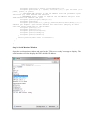
Step Two: Get the Shield's IP Address
Open the serial monitor window and wait for the "Web server ready" message to display. The
serial monitor will also display the WiFi shield's IP address:
Arduino program serial comm output. The IP address of the shield is highlighted.
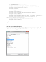
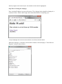
Step Three: Visiting the webpage
Now visit that IP address in your web browser. The webpage below should be displayed, it
contains a link to Yahoo! and Google and a button that doesn't do anything (yet):
A simple webpage with two links and one button served from the WiFi shield.
When the webpage is visited the serial monitor window will also display a "New Browser
Request!" string as shown below:
The Arduino serial comm window showing that it detected a new browser connection/request.
Note: In the case of some browsers, like Google Chrome, even typing the URL in the bar sends a
webpage request, this is because these browsers try to get the webpage's title for the user's
convenience even before he/she visits the webpage.
Example 5: Controlling The Arduino Digital Pins From a Webpage (Toggling LEDs From an
Webpage)
In this example we will create a webpage with three buttons to control three different digital pins
in the Arduino.
For this tutorial follow the steps below. We have also created a video where we explain the code
in more detail.
Video - WiFi Shield Arduino Digital Pin Control From Webpage
Step 1: Hardware
Connect three LEDs and resistor to digital pins 11, 12, and 13 as shown in the schematic below:
Three LEDs and 1k resistors connected to pins 11, 12, and 13.
Step 2: Arduino Sketch
Upload the following code to your Arduino board but replace "mySSID" and "myPassword"
with your access point's SSID name and password:
#include <SoftwareSerial.h>
#include "WiFly.h"
#define SSID
"mySSID"
#define KEY
"myPassword"
// check your access point's security mode, mine was WPA20-PSK
// if yours is different you'll need to change the AUTH constant, see the
file WiFly.h for avalable security codes
#define AUTH
WIFLY_AUTH_WPA2_PSK
int flag = 0;
// Pins' connection
// Arduino
WiFly
// 2
<---->
TX
// 3
<---->
RX
SoftwareSerial wiflyUart(2, 3); // create a WiFi shield serial object
WiFly wifly(&wiflyUart); // pass the wifi siheld serial object to the WiFly
class
char ip[16];
void setup()
{
pinMode(11,OUTPUT);
digitalWrite(11,LOW);
pinMode(12,OUTPUT);
digitalWrite(12,LOW);
pinMode(13,OUTPUT);
digitalWrite(13,LOW);
wiflyUart.begin(9600); // start wifi shield uart port
Serial.begin(9600); // start the arduino serial port
Serial.println("--------- WIFLY Webserver --------");
// wait for initilization of wifly
delay(1000);
wifly.reset(); // reset the shield
delay(1000);
//set WiFly params
wifly.sendCommand("set ip local 80\r"); // set the local comm port to 80
delay(100);
wifly.sendCommand("set comm remote 0\r"); // do not send a default string
when a connection opens
delay(100);
wifly.sendCommand("set comm open *OPEN*\r"); // set the string that the
wifi shield will output when a connection is opened
delay(100);
Serial.println("Join " SSID );
if (wifly.join(SSID, KEY, AUTH)) {
Serial.println("OK");
} else {
Serial.println("Failed");
}
wifly.sendCommand("get ip\r");
wiflyUart.setTimeout(500);
if(!wiflyUart.find("IP="))
{
Serial.println("can not get ip");
while(1);;
}else
{
Serial.print("IP:");
}
char c;
int index = 0;
while (wifly.receive((uint8_t *)&c, 1, 300) > 0) { // print the response
from the get ip command
if(c == ':')
{
ip[index] = 0;
break;
}
ip[index++] = c;
Serial.print((char)c);
}
Serial.println();
while (wifly.receive((uint8_t *)&c, 1, 300) > 0);;
Serial.println("Web server ready");
}
void loop()
{
if(wifly.available())
{ // the wifi shield has data available
if(wiflyUart.find("*OPEN*")) // see if the data available is from an open
connection by looking for the *OPEN* string
{
Serial.println("New Browser Request!");
delay(1000); // delay enough time for the browser to complete sending
its HTTP request string
if(wiflyUart.find("pin=")) // look for the string "pin=" in the http
request, if it's there then we want to control the LED
{
Serial.println("LED Control");
// the user wants to toggle the LEDs
int pinNumber = (wiflyUart.read()-48); // get first number i.e. if
the pin 13 then the 1st number is 1
int secondNumber = (wiflyUart.read()-48);
if(secondNumber>=0 && secondNumber<=9)
{
pinNumber*=10;
pinNumber +=secondNumber; // get second number, i.e. if the pin
number is 13 then the 2nd number is 3, then add to the first number
}
digitalWrite(pinNumber, !digitalRead(pinNumber)); // toggle pin
// Build pinstate string. The Arduino replies to the browser with
this string.
String pinState = "Pin ";
pinState+=pinNumber;
pinState+=" is ";
if(digitalRead(pinNumber)) // check if the pin is ON or OFF
{
pinState+="ON"; // the pin is on
}
else
{
pinState+="OFF"; // the pin is off
}
// build HTTP header Content-Length string.
String contentLength="Content-Length: ";
contentLength+=pinState.length(); // the value of the length is the
lenght of the string the Arduino is replying to the browser with.
// send HTTP header
wiflyUart.println("HTTP/1.1 200 OK");
wiflyUart.println("Content-Type: text/html; charset=UTF-8");
wiflyUart.println(contentLength); // length of HTML code
wiflyUart.println("Connection: close");
wiflyUart.println();
// send response
wiflyUart.print(pinState);
}
else
{
// send HTTP header
wiflyUart.println("HTTP/1.1 200 OK");
wiflyUart.println("Content-Type: text/html; charset=UTF-8");
wiflyUart.println("Content-Length: 540"); // length of HTML code
wiflyUart.println("Connection: close");
wiflyUart.println();
// send webpage's HTML code
wiflyUart.print("<html>");
wiflyUart.print("<head>");
wiflyUart.print("<title>WiFi Shield Webpage</title>");
wiflyUart.print("</head>");
wiflyUart.print("<body>");
wiflyUart.print("<h1>LED Toggle Webpage</h1>");
// In the <button> tags, the ID attribute is the value sent to the
arduino via the "pin" GET parameter
wiflyUart.print("<button id=\"11\" class=\"led\">Toggle Pin
11</button> "); // button for pin 11
wiflyUart.print("<button id=\"12\" class=\"led\">Toggle Pin
12</button> "); // button for pin 12
wiflyUart.print("<button id=\"13\" class=\"led\">Toggle Pin
13</button> "); // button for pin 13
wiflyUart.print("<script
src=\"http://ajax.googleapis.com/ajax/libs/jquery/2.1.3/jquery.min.js\"></scr
ipt>");
wiflyUart.print("<script type=\"text/javascript\">");
wiflyUart.print("$(document).ready(function(){");
wiflyUart.print("$(\".led\").click(function(){");
wiflyUart.print("var p = $(this).attr('id');"); // get id value (i.e.
pin13, pin12, or pin11)
// send HTTP GET request to the IP address with the parameter "pin"
and value "p", then execute the function
// IMPORTANT: dont' forget to replace the IP address and port with
YOUR shield's IP address and port
wiflyUart.print("$.get(\"http://");
wiflyUart.print(ip);
wiflyUart.print(":80/a\", {pin:p},function(data){alert(data)});");//
execute get request. Upon return execute the "function" (display an alert
with the "data" send back to the browser.
wiflyUart.print("});");
wiflyUart.print("});");
wiflyUart.print("</script>");
wiflyUart.print("</body>");
wiflyUart.print("</html>");
}
Serial.println("Data sent to browser");
}
}
}
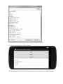
Step 3: Serial Monitor Window
Open the serial monitor window and wait for the "Web server ready" message to display. The
serial monitor will also display the WiFi shield's IP address:
Arduino program serial comm output. The IP address of the shield is highlighted.
Step 4: Visit The Webpage
Visit the IP address in a web browser. A webpage with three buttons, like the one below, should
display. Click on the buttons to control the LEDs.
LED control webpage served from the WiFi shield.
The Arduino will also respond back to the web browser with the pin's state, the browser will
display this in an alert window.
Alert dialog displaying the state of Pin12, The string Pin12 is ON was sent from the Arduino.
The serial monitor window will also show when a browser sends a request to either visit the
webpage or control the LED pins.
Arduino serial comm output when an HTTP request is sent to the shield.
Example 6: WiFi Shield and Android App
The Android app you can use to control the Arduino's pins through the WiFi or Ethernet Shield.
Android Application
We've created an Android app that can toggle the digital pins in the Arduino through the WiFi
shield, to see how the app works and learn about the code watch the video in this link:
Video - WiFi Shield Android App for Arduino Pin Control
Software
Download the Android Studio project/source form this link:
File:WiFiShieldLEDControl.zip
Example 7: Sending Data To and Retrieving Data From an External Server
The RN-171 module in the WiFi shield has the ability to act as an HTML client (a text based
web browser essentially), this means that we can use the shield to send and receive data from a
web server. In this example you will learn to use the shield with a web Application Programming
Interface (API) that displays any city's weather data (i.e. temperature, humidity, etc).
The name of the API we'll use is OpenWeatherMap, when you send the name of a city and
country to this website it returns a JSON string with weather information. If you want to display
the weather for London UK for example you would visit the following URL
http://api.openweathermap.org/data/2.5/weather?q=London,uk which would return a JSON
string like the following, where the weather data and other information is embedded.
{
"coord":{"lon":-0.13,"lat":51.51},
"sys":{"type":3,"id":60992,"message":0.0079,"country":"GB","sunrise":14213950
87,"sunset":1421425352},
"weather":[{"id":802,"main":"Clouds","description":"scattered
clouds","icon":"03n"}],
"base":"cmc stations",
"main":{
"temp":277.25,"humidity":79,"pressure":998.4,
"temp_min":277.25,"temp_max":277.25
},
"wind":{
"speed":2,"gust":5,"deg":180},
"rain":{"3h":0},"clouds":{"all":32},
"dt":1421372140,"id":2643743,"name":"London","cod":200
}
Step 1: The URL
Let us go ahead and retrieve the weather JSON string for San Francisco, US. The URL our WiFi
shield needs to visit is the following (you may test it in your web browser):
http://api.openweathermap.org/data/2.5/weather?q=San%20Francisco,US
Step 2: The Arduino Code
Section 13 of the WiFly manual teaches you different ways to connect to a web server, but in all
cases we need to specify the name of the server (or IP address if the server does not have a
domain name), and then the data we wish to send.
The commands we need to send to the WiFi shield to receive the JSON string from the
OpenWeatherMap server are the following:
set ip proto 18 //enable html client
set dns name api.openweathermap.org //name of your webserver
set ip address 0 // so WiFly will use DNS
set ip remote 80 // standard webserver port
set com remote 0 // turn off the REMOTE string so it does not interfere with
the post
open // to open the connection
GET /data/2.5/weather?q=San%20Francisco,US \n\n // to send the data
This is the arduino code that will send the commands:
#include <SoftwareSerial.h>
#include "WiFly.h"
#define SSID
"mySSID"
#define KEY
"myPassword"
// check your access point's security mode, mine was WPA20-PSK
// if yours is different you'll need to change the AUTH constant, see the
file WiFly.h for avalable security codes
#define AUTH
WIFLY_AUTH_WPA2_PSK
// Pins' connection
// Arduino
WiFly
// 2
<---->
TX
// 3
<---->
RX
SoftwareSerial wiflyUart(2, 3); // create a WiFi shield serial object
WiFly wifly(&wiflyUart); // pass the wifi siheld serial object to the WiFly
class
void setup()
{
wiflyUart.begin(9600); // start wifi shield uart port
Serial.begin(9600); // start the arduino serial port
Serial.println("--------- OpenWeatherMap API --------");
// wait for initilization of wifly
delay(3000);
wifly.reset(); // reset the shield
Serial.println("Join " SSID );
if (wifly.join(SSID, KEY, AUTH)) {
Serial.println("OK");
} else {
Serial.println("Failed");
}
wifly.sendCommand("set ip proto 18\r"); //enable html client
delay(100);
wifly.sendCommand("set dns name api.openweathermap.org\r"); // name of the
webserver we want to connect to
delay(100);
wifly.sendCommand("set ip address 0\r"); // so WiFly will use DNS
delay(100);
wifly.sendCommand("set ip remote 80\r"); /// standard webserver port
delay(100);
wifly.sendCommand("set com remote 0\r"); // turn off the REMOTE string so
it does not interfere with the post
delay(100);
wifly.sendCommand("open\r"); // open connection
delay(100);
wiflyUart.print("GET /data/2.5/weather?q=San%20Francisco,US \n\n");
delay(1000);
}
void loop()
{
//As soon as the data received from the Internet ,output the data through
the UART Port .
while (wifly.available())
{
Serial.write(wifly.read());
}
}
Step 3: Result
Open the serial monitor window, you should be able to see the same JSON string you saw in the
browser.
JSON weather string shown in the Arduino serial monitor window.
Example 8: TCP Communication With Terminal
In this example we'll show you how to send information from the WiFi shield to a PC terminal
program. We'll make a simple Arduino console with menus that will give you the option to see
the Arduino digital pin's state and toggle them.
Step 1: Download a TCP Terminal
Download and install RealTerm, a utility terminal that will allow us to connect to the WiFi
shield.
Step 2: Arduino Code
Upload the code below to your Arduino board replacing "mySSID", "myPassword", and
authentication code with your own access point's information:
#include <SoftwareSerial.h>
#include "WiFly.h"
#define SSID
"mySSID"
#define KEY
"myPassword"
// check your access point's security mode, mine was WPA20-PSK
// if yours is different you'll need to change the AUTH constant, see the
file WiFly.h for avalable security codes
#define AUTH
WIFLY_AUTH_WPA2_PSK
#define FLAG_MAIN_MENU 1
#define FLAG_SUB_MENU_2 2
int flag = FLAG_MAIN_MENU;
// Pins' connection
// Arduino
WiFly
// 2
<---->
TX
// 3
<---->
RX
SoftwareSerial wiflyUart(2, 3); // create a WiFi shield serial object
WiFly wifly(&wiflyUart); // pass the wifi siheld serial object to the WiFly
class
void setup()
{
// define the pins we can control
pinMode(11,OUTPUT);
digitalWrite(11,LOW);
pinMode(12,OUTPUT);
digitalWrite(12,LOW);
pinMode(13,OUTPUT);
digitalWrite(13,LOW);
pinMode(7,OUTPUT);
digitalWrite(7,LOW);
wiflyUart.begin(9600); // start wifi shield uart port
Serial.begin(9600); // start the arduino serial port
Serial.println("--------- TCP Communication --------");
// wait for initilization of wifly
delay(1000);
wifly.reset(); // reset the shield
delay(1000);
wifly.sendCommand("set ip local 80\r"); // set the local comm port to 80
delay(100);
wifly.sendCommand("set comm remote 0\r"); // do not send a default string
when a connection opens
delay(100);
wifly.sendCommand("set comm open *\r"); // set the string or character that
the wifi shield will output when a connection is opened "*"
delay(100);
wifly.sendCommand("set ip protocol 2\r"); // set TCP protocol
delay(100);
Serial.println("Join " SSID );
if (wifly.join(SSID, KEY, AUTH)) {
Serial.println("OK");
} else {
Serial.println("Failed");
}
wifly.sendCommand("get ip\r");
char c;
while (wifly.receive((uint8_t *)&c, 1, 300) > 0) { // print the response
from the get ip command
Serial.print((char)c);
}
Serial.println("TCP Ready");
}
void loop()
{
if(wifly.available())
{
delay(1000); // wait for all the characters to be sent to the WiFi shield
char val = wiflyUart.read(); // read the first character
if(flag == FLAG_MAIN_MENU)
{
switch(val)
{
case '*': // search for the new connection string
printMainMenu();
break;
case '1': // the user typed 1, display the pin states
printPinStates();
printMainMenu();
break;
case '2': // the user typed 2, display the sub menu (option to
select a particular pin)
printSubMenu2();
flag = FLAG_SUB_MENU_2; // flag to enter the sub menu
break;
default:
wiflyUart.print("INVALID SUBMENU\r\n");
break;
}
}
else if(flag == FLAG_SUB_MENU_2)
{
int pinNumber = val-48; // get first number i.e. if the pin 13 then
the 1st number is 1
int secondNumber = (wiflyUart.read()-48);
if(secondNumber>=0 && secondNumber<=9)
{
pinNumber*=10;
pinNumber +=secondNumber; // get second number, i.e. if the pin
number is 13 then the 2nd number is 3, then add to the first number
}
// Create the "You want to toggle pin x ? OK..." string.
String response = "\r\nYou want to toggle pin ";
response+=pinNumber;
response+="? OK...\r\n";
wiflyUart.print(response);
digitalWrite(pinNumber, !digitalRead(pinNumber)); // toggle pin
wiflyUart.print("Pin Toggled!\r\n"); // let user know the pin was
toggled.
printMainMenu();
flag = FLAG_MAIN_MENU;
}
}
}
/**
* Prints the main menu options
*/
void printMainMenu()
{
wiflyUart.print("\r\n\r\n");
wiflyUart.print("Arduino Console Menu: \r\n");
wiflyUart.print("1. Show digital pin states\r\n");
wiflyUart.print("2. Toggle a digital pin's state\r\n");
wiflyUart.print("\r\n\r\n");
}
// displays the pin states
void printPinStates()
{
String pinState = "Pin 7 is ";
pinState+=getPinState(7);
pinState+="\r\n";
pinState += "Pin 11 is ";
pinState+=getPinState(11);
pinState+="\r\n";
pinState += "Pin 12 is ";
pinState+=getPinState(12);
pinState+="\r\n";
pinState += "Pin 13 is ";
pinState+=getPinState(13);
pinState+="\r\n";
wiflyUart.print(pinState);
}
// prints the option to enter a pin number
void printSubMenu2()
{
wiflyUart.print("\r\nEnter the pin number you wish to toggle: ");
}
// get a pin state as a string.
String getPinState(int pinNumber)
{
if(digitalRead(pinNumber)) // check if the pin is ON or OFF
{
return "ON"; // the pin is on
}
else
{
return "OFF";
}
// the pin is off
}
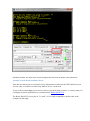
Step 3: Obtain the Shield's IP Address and Port
Open the Arduino serial monitor window to obtain the WiFiShield's IP address and port number,
highlighted in the image below.
Arduino serial monitor window output from TCP example, the ip address and port number are
highlighted.
In the image above the IP Address and Port would be the following:
192.168.0.10:80
Step 4: Configure The TCP Terminal and Connect to The Shield
Open RealTerm and in the "Display" tab enter "30" for "Rows" and select the "Scrollback"
option:
RealTerm window: rows = 30, and Scrollback option checked.
In the "Port" tab of the RealTerm program, type your shield's IP address and port e.g.
192.168.0.10:80, then click the "Open" button, the Arduino's hard coded main menu should
display in the terminal.
RealTerm window. Port field has WiFi shield's IP address and port number. The Arduino's menu is
displayed
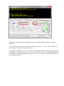
In the "Send" tab select one of the options from the menu either "1" or "2", enter it in the text
box and press "Send ASCII" to send the value.
For example, to toggle pin 13 enter "2" and press "Send ASCII", then when prompted "Enter the
pin number you wish you toggle" enter "13" and click "Send ASCII". The Arduino should reply
"Pin Toggled!" and go back to the main menu, now enter "1" and press "Send ASCII" to see the
present state of the pins.
RealTerm window. The state of pin 13 was changed from OFF to ON as shown in the yellow text.
Example 9: WiFi Shield and Relay Shield
Now that you know how to send and receive information to and from the WiFi shield you can
see how easy it would be to control any kind of device via the web.
If you wish to control high power devices such as your desk lamp, a motor, or a water pump via
a webpage or phone application we recommend our Relay Shield V2.0.
The Relay Shield V2.0 uses pins 4, 5, 6, and 7 so it is fully compatible with the code in the
examples in this page.
Example 10: Adhoc Mode
To use the shield in Adhoc mode, as an access point, simply connect pin IO9 from the shield to
the 3.3V pin in the Arduino, as shown below, and reset the shield if it was on.
Shield connection required for adhoc mode. Pin IO9 of the shiled connected to 3.3V.
To obtain the shield's SSID upload the code in Example 1 to your Arduino and open the serial
monitor, the shield will respond with it's SSID as in the example below, where in this case
WiFly-EZX-1b is the SSID.
AP mode as WiFly-EZX-1b on chan 1
You should now be able to connect to your WiFi shield as an access point, for example the SSID
should be visible in your PC's list of WiFi networks available.
To learn more about adhoc mode check out the WiFly RN User Manual section 16 "Adhoc
Networking Mode"
Related Reading
What is a Seeeduino
w3schools Great website to learn HTML, Javascript, and JQuery
Version Tracker
Here lists the comparison between various versions of WiFi Shield:
Parameter
Wifi Shield
V1.0
Wifi Shield
V1.1(v1.2)
Wifi Shield V2.0
Voltage
+3.5V~+5V
+3.5V~+5V
+3.5V~+5V
Standard Shield
Yes
Yes
Yes
Communication Mode
Serial port
Serial port
Serial port
Standard Shield
No
Yes
Yes
Antenna Type
Library File
mast antenna PCB antenna
onboard antenna
New Wifi Shield
Wifi Shield
New Wifi
Library the same to
Library V1.0 Shield Library
v1.2
Resources
WiFi Shield V2.0 Eagle Files
Schematic PDF
RN-171 Datasheet
Wifi Shield Library
WiFi Module User Manual -- This is where you'll find all the commands for the RN-171 module in
the shield.