1
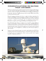
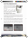
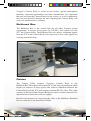
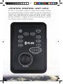
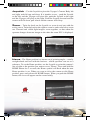
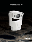
VOYAGER OPERATOR’S MANUAL Voyager Manual.indd 1 12/10/07 10:57:50 AM Voyager Manual.indd 2 12/10/07 10:57:51 AM TABLE OF CONTENTS 1 - CAUTIONS 6 2 - OPERATION 7-14 2.1 System Description 2.2 Joystick Control Unit (JCU) 2.3 Voyager Controls 8 10 11 3 MENUS 1518 3 GETTING STARTED 1922 4 - CARE AND MAINTENANCE 23-24 4 - FUNDAMENTALS OF INFRARED 25-32 4.1 Intro to Infrared Technology 26 4.2 More About Infrared 28 5 - APPENDIX 5.1 Parts and Accessories 5.2 Specifications Voyager Manual.indd 3 33-35 34 35 12/10/07 10:57:52 AM FLIR Systems, Inc. CVS World Headquarters FLIR Systems, Inc. 70 Castilian Dr. Goleta, CA 93117 USA PH: + 1 877 773 3547 PH: + 1 805 964 9797 FX: + 1 805 685 2711 [email protected] EUROPE CVS Eurasian Headquarters FLIR Systems CVS BV Charles Petitweg 21 4847 NW Teteringen Breda Netherlands PH: + 31 (0) 765 79 41 94 FX: + 31 (0) 765 79 41 99 [email protected] FLIR Systems, Inc. Corporate Headquarters FLIR Systems, Inc. 27700A SW Parkway Ave. Wilsonville, OR 97070 USA PH: + 1 877 773 3547 FX: + 1 503 498 3904 [email protected] Equipment described herein may require US Government authorization for export purposes. Diversion contrary to US law is prohibited. ©2007 FLIR Systems, Inc. Specifications are subject to change without notice, check our website: www.fl ir.com. 4 Voyager Manual.indd 4 12/10/07 10:57:54 AM CONGRATULATIONS ON BUYING YOUR VOYAGER… Welcome to the pioneering world of maritime thermal imaging! The Voyager is a state-of-the-art thermal imager that lets you see at night, through smoke and haze, without any lighting at all. FLIR has been building thermal imagers for decades, and we are confident that you will see why FLIR is the #1 name in infrared around the world. Thermal imaging technology has been a staple of military operations for decades, but FLIR has just recently made it available to the public, and only to a select few at that! By purchasing a FLIR thermal imager, you have established yourself as a mariner on the leading edge of technological advancement. Remember to register your Voyager by fi lling out the Registration card. You will find that the Voyager is simple to use; it includes a Camera Body to install on the deckhouse or mast location of your choice, a Bulkhead Box for installation below deck, and a Joystick Control Unit (JCU) for installation at the primary pilot station. Voyager will support up to 4 control stations onboard and the video can be displayed on virtually any multi-function display or video monitor. Voyager uses two thermal imagers: one with a wide field-of-view (FOV) for navigating and overall situational awareness, and another longer-range imager for hazard and vessel identification. Both cameras provide clear imagery regardless of lighting conditions. 5 Voyager Manual.indd 5 12/10/07 10:57:56 AM CAUTIONS In the Voyager Operator’s Manual, CAUTION notices indicate a potential hazard, which, if not avoided, may damage you, someone else, or the Voyager. For safety, and to achieve the highest levels of performance from your Voyager, always follow these Cautions when handling and operating your Voyager camera system. CAUTION! Failure to follow the caution may result in damage to the Voyager. CAUTION! • Do not use the Voyager imaging system as your primary navigation system. Use it in conjunction with other navigation aids and a primary manual navigation system. • Do not open the Voyager camera body for any reason. Disassembly of the camera (including removal of the cover) can cause permanent damage and will void the warranty. • Be careful not to leave fingerprints on the Voyager’s infrared camera optics. They are treated with a special coating that can be permanently damaged by the oils in your skin. Also, they are delicate and can be damaged with improper cleaning. • The Voyager runs off of 24 VDC. Operating the camera outside of the specified input voltage range or the specified operating temperature range can cause permanent damage. • Do not use the thermal imager to look at high-intensity radiation sources like the sun, lasers, arc welders, etc., as prolonged exposure can damage the imagers. • The Voyager is designed to withstand the shocks and vibrations commonly encountered in the normal maritime environment. Don’t expose the camera to excessive impacts. • Don’t paint your Voyager, as this may void your warranty 6 Voyager Manual.indd 6 12/10/07 10:57:57 AM OPERATION Voyager Manual.indd 7 12/10/07 10:57:58 AM SYSTEM DESCRIPTION Voyager is a stabilized maritime thermal and visible-light camera system for use on nearly any kind of vessel. It uses two thermal imagers to provide wide-angle and telephoto zoom images, instead of one imager with a long telescope. The Voyager consists of three main components: the Camera Body, Joystick Control Unit (JCU), and Bulkhead Box. Each of these components is designed for years of rugged, trouble-free use. The Voyager Camera Body The Camera Body’s pan/tilt mechanism allows the operator to look 360° in azimuth, and +/- 90° in elevation. The Camera Body houses all three of Voyager’s imaging sensors: wide-angle infrared, long-range infrared, and zoom color daylight/low-light camera. Each of the infrared cameras uses an uncooled vanadium oxide (VOx) detector sensitive to long-wave infrared (LWIR) energy. The wide-angle camera uses a 35mm lens, and the long-range camera uses a 140mm lens. In its default setting, Voyager will zoom digitally from the wide FOV camera to the narrow FOV camera. At that point, the system switches seamlessly over to the narrow FOV camera and zooms digitally to its maximum magnification. 8 Voyager Manual.indd 8 12/10/07 10:58:01 AM Voyager’s Camera Body is sealed at the factory against atmospheric humidity, suspended particulates and other contaminates. It is important that you not open the Camera Body for any reason, as it will compromise this seal and possibly damage the unit. Opening the Camera Body will void your manufacturer’s warranty. Bulkhead Box The Bulkhead Box is the central hub for all other Voyager system components. It accepts vessel power in (24VDC), and exports it to the JCU and Camera Body. The Bulkhead Box also passes command signals from the JCU to the Camera Body, and exports up to four video signals for viewing around the ship. Cables The Camera Cable connects Voyager’s Camera Body to the Bulkhead Box. This cable will be either 50’ or 100’ long, depending on which length you ordered. It relays power and control commands between the Camera Body and the JCU, and outputs standard RS-170 video. This cable connects to the back of the Camera Body base with a circular connector. It is important not to bend this cable too tightly. Detailed instructions for connecting the cable to the Bulkhead Breakout Box are included in the Installation Guide. 9 Voyager Manual.indd 9 12/10/07 10:58:03 AM JOYSTICK CONTROL UNIT (JCU) The JCU is your primary method of control for the Voyager. It allows you to point the Voyager, zoom the cameras in and out, switch between infrared and visible-light cameras, focus, and adjust Voyager’s image quality, among other functions. In conjunction with the Joystick, Voyager provides Accu-Point, a complete set of on-screen symbology, so you can see where the camera is pointed at all times. 10 Voyager Manual.indd 10 12/10/07 10:58:05 AM VOYAGER’S CONTROLS Each of the JCU’s functions, and their corresponding on-screen symbology, are described in this section. DESCRIPTION Power – Press this button to turn the system On and Off. When turning the system On, two splash screens will display. When the thermal image is displayed along with the pan and tilt symbols the Voyager is ready to use. It will take approximately 40 seconds before the system is completely active; a “LOADING, PLEASE WAIT...” message will display until the Voyager is ready for use. When turning Voyager Off, drive the Camera Body to the Park position with the Joystick (described below), and press the Power button to deactivate the system. Voyager is in the Park position when its optics are pointed straight down. This position protects the cameras from damage when not in use. Park the Voyager before turning the Voyager Off. Setup – Press this button to access the Setup menus. (See Menu section for full explanation.) VIS/IR – Press this button to switch between IR and visible-light cameras and back, as desired. Dim – Voyager’s JCU controls are backlit to make them easier to see at night. This button controls the brightness of the JCU backlighting, so you can adjust it for your comfort. Press this button to cycle through the four different settings or levels of brightness. 11 Voyager Manual.indd 11 12/10/07 10:58:06 AM Joystick – Use the Joystick to pivot the Voyager’s Camera Body left and right, and tilt it up and down. It is intuitive to use – push the Joystick to the left, and the Voyager will pivot left, push the Joystick to the right and the Voyager will pivot to the right. Push the Joystick forward and the camera will tilt down, pull it back and the camera will tilt up. Zoom – Twist the knob on the Joystick to zoom in and out with the active sensor. Twist the knob to the right to zoom in, and to the left to zoom out. Thermal and visible-light imagers zoom together, so that when the operator changes from one imager to the other the same FOV is displayed. Home – The Home position is a known set of pointing angles – usually straight ahead and level with the horizon – which operators can use as a reference. To set the Home position, use the Joystick to point the camera’s line of sight to the position you want to set as “Home.” Press and hold the HOME button for 3 seconds; the Home symbol will flash when the new Home position is set. When you want to drive the camera to this Home position, press and release the HOME button. When you push the HOME button, this icon will appear on the screen briefly. Home Icon 12 Voyager Manual.indd 12 12/10/07 10:58:07 AM Stab – Pressing this button cycles the 2-axis gyro-stabilization on and off. Point – The Point command turns off the Voyager’s pan stabilization. This can be helpful when you want Voyager to stay pointing in the same position relative to the vessel in a turn. Night – Voyager’s infrared imagery is normally black and red video. The NIGHT control toggles the IR imagery from black and red to black and white. Two rainbow color palettes are also available via the Setup menu. Focus – The Wide FOV thermal imager has a fixed focus; the operator can’t adjust it. If the operator tries to adjust the Wide imager’s focus, the Focus symbology will flash. The Autofocus (AF) and Manual focus (the IN and OUT buttons) control only the Narrow FOV thermal imager. Use the Manual Focus controls for coarse focus adjustment and press the AF button for fine focus adjustments of the thermal image. The visible-light camera uses a continuous autofocus and its focus cannot be adjusted manually. 13 Voyager Manual.indd 13 12/10/07 10:58:08 AM Scene – Voyager has four available auto-gain correction (AGC) settings: Day Running, Night Running, Night Docking and Man Overboard (shown below). Pressing this button toggles between these four presets. The infrared cameras in Voyager automatically adjust to the scenes they are viewing to provide you with the optimal image quality. However, you may want to view different areas of the temperature spectrum, or prefer an image that has more or less contrast than that provided. Toggling between these four presets will change the image gain and level settings used as a baseline. Which setting to use comes down to personal preference – if you like the way the Man Overboard setting looks, even though you are running on open water during the daytime, use it. Night Running Day Running Man Overboard Night Docking The Voyager system operation is intuitive and straightforward, but the more you use it the more you will get out of it. In turn, the more you know about your Voyager, the more you will like it. 14 Voyager Manual.indd 14 12/10/07 10:58:09 AM MENUS Voyager Manual.indd 15 12/10/07 10:58:10 AM MENUS Voyager’s menus allow the operator to customize certain system features. Pressing the SETUP button will activate the Voyager’s menu structure. Voyager is continually evolving as FLIR incorporates product improvements, so the menus you see may be slightly different from the ones shown here. If you have any questions, call an Applications Expert at 1.888.747.FLIR. To navigate the menus, use the Joystick to move the cursor up and down from one selection to the next. To activate a selection, move the Joystick left or right. Once you are satisfied with your changes, press the SETUP button to exit the menus. The Setup menu will time-out and disappear if it is left on for 30 seconds with no activity. Each of the menu items are explained on the next page. 16 Voyager Manual.indd 16 12/10/07 10:58:11 AM Elevation Icon – Selecting this item toggles the elevation icon on and off. Some operators prefer an image less cluttered with symbology, so they turn this icon off. Disable Set Video Polarity – Selecting this item will toggle the infrared imagery from white-hot (or red-hot, if the NIGHT setting is active) to black-hot. The difference between white-hot and black-hot are below; white-hot is on the left and black-hot on the right. The use of white-hot or black-hot display mode is strictly a personal preference; experiment with the different settings in different conditions and see which you prefer. – If the operator has selected to leave the Foveal View (picture-in-picture) active, the thermal images may require a small amount of alignment to counteract parallax. Select this item and use the Joystick to steer the inner image around until it is aligned with the outer image. Align Thermal Images – Operators can view Voyager’s two thermal imagers separately – with steps of electronic zoom providing transition from one to the other – or overlaid, with the Narrow FOV image nested within the Wide FOV image. This nested image presentation is a “Foveal” view, and lets the operator zoom from the Wide FOV to the Narrow without losing image resolution. Activating this menu selection toggles Foveal view on and off. Enable Foveal View 17 Voyager Manual.indd 17 12/10/07 10:58:12 AM Enable Color Thermal Video – Some operators prefer to look at their thermal images in color instead of grayscale. Selecting this menu item will activate two color palettes, called “rainbow” and “fusion,” and change the function of the JCU’s NIGHT button to cycle through all four settings instead of just two: grayscale, red, rainbow and fusion. – Selecting this menu item will turn all of the on-screen icons off except when their corresponding controls are actively in use. Hide Icons Display Version Info – Should a factory representative need to know your Voyager’s software revision levels, they can be found by selecting this menu item. Restore Factory Defaults Voyager to its factory default settings – Select this item to restore your 18 Voyager Manual.indd 18 12/10/07 10:58:13 AM GETTING STARTED Voyager Manual.indd 19 12/10/07 10:58:14 AM The qualified technician who installed your Voyager isolated it from vessel power with a customer-supplied switch or circuit breaker. The first step to take in using your Voyager is to make sure that this switch or circuit breaker is turned on. After that, turn on your display and select the Voyager as the video source for your display. (Remember that most multi-function displays (MFDs) allow you to select from a number of available inputs.) Finally, press the Power button on the JCU to turn the Voyager on. From there, use the controls on the Joystick Control Unit (JCU) to operate and configure your Voyager. If you choose to operate your Voyager with engines off, be aware that this may drain power from your batteries, unless connected to shore power and equipped with a suitable battery tender. The Voyager will go through its start-up routine – two splash screens will display for a few seconds, the IR wide FOV will display, and when the pointing icons are displayed, the system is ready to go (see images below). You will notice that the Voyager starts up in red-hot mode. This is because many users will be turning Voyager on when there is little or no light available, and is an effort to safeguard the operator’s night vision. If you would prefer to use white-hot display mode, simply press the NIGHT button on the JCU. 20 Voyager Manual.indd 20 12/10/07 10:58:15 AM Move the Joystick to the left and right to pan the camera body left and right, and see how the image responds on your monitor. The Joystick is pressure-sensitive; the farther you deflect it from center, the faster the camera will move. With a little practice, it won’t take long before you will be able to follow moving objects in the air and on the water. After you are familiar with how to make the camera point at what you want to see, take a look at the infrared image itself. Voyager’s thermal imagers don’t make pictures from light like the visible-light camera does; it senses differences in temperature and makes images based on those differences. When Voyager is in white-hot polarity, the warm things in the scene will display as white, or lighter shades of grey, and cold objects will display as black or darker shades of gray. (When you configure the Voyager for black-hot polarity, this will be reversed.) As you use the Voyager during daylight and nighttime, you will notice differences in the picture quality – this is normal. Objects absorb heat energy from the sun during the day, and radiate this energy off at night, so thermal contrast – and therefore how things will appear to the Voyager – will change based on the time of day, and the weather. 21 Voyager Manual.indd 21 12/10/07 10:58:16 AM Voyager automatically adjusts to these changing scene conditions to try and give you the best possible picture. The camera contains four preset conditions that might provide better imagery in certain conditions: Night Running, Day Running, Man Overboard, and Night Docking. While these names indicate their intended use, varying environmental conditions might make another setting preferable; night running while in a harbor, for instance. Experiment with the different settings, and find out for yourself which setting works best in different conditions. Four images showing the changes apparent in each setting are shown below. Night Running Day Running Man Overboard Night Docking As you experiment with your Voyager, you will see your world in a different light. Consider every object you view in terms of how it will look “thermally” as opposed to how it looks to your eye. Right after sunset, objects warmed by the sun will appear warmest. Early in the morning, many of these objects will appear cooler than their surroundings, so be sure to look for subtle differences in the scene, as opposed to just hot targets. If you have any questions about the operation of your Voyager, or you would like to provide feedback on the product, please feel free to call us at 1.888.747.FLIR in the United States. 22 Voyager Manual.indd 22 12/10/07 10:58:17 AM CARE AND MAINTENANCE Voyager Manual.indd 23 12/10/07 10:58:18 AM TROUBLESHOOTING CAUTION! Do not open the camera body for any reason. Disassembly of the camera (including removal of the cover) can cause permanent damage and will void the warranty. The Voyager is a simple, yet sophisticated device, built to provide years of trouble-free use. If you do run into problems with your Voyager, try these simple steps: • If the camera will not produce an image, check the fuses in the Breakout Box first. Make sure that power to the Voyager is off, and remove the fuses one at a time, checking to see if they are still intact. If one of the fuses has blown, determine the cause of the blown fuse, fi x the problem, and replace with one of the spare fuses supplied. • Check the wiring at both the electrical panel and at the termination to the JCU. Ensure that the contacts are clean dry and free from corrosion. If maintenance on the wiring connection is required, have an authorized service representative make the appropriate repairs. • If the camera still will not produce an image, check the video connection at the camera and at your display. If the connectors appear to be properly engaged but the camera still does not produce an image, have an authorized service representative make the appropriate repairs. CLEANING CAUTION! Clean the camera window only with low-pressure fresh water and a soft cloth. CAUTION! Improper care of the camera window can cause damage to its anti-reflective coating, degrade the camera’s performance, and void the camera warranty. The camera housing has a durable marine coating. Rinse the camera housing with very low-pressure fresh water to keep it clean. If the front window of the camera gets water spots, wipe it with a clean lens cloth folded in fourths and dampened with fresh water. 24 Voyager Manual.indd 24 12/10/07 10:58:19 AM FUNDAMENTALS OF INFRARED Voyager Manual.indd 25 12/10/07 10:58:20 AM INTRO TO INFRARED TECHNOLOGY The Voyager detects differences in heat and displays them as black and white TV video. It may look like a black and white version of what your eyes see, but it’s not. The Voyager sees heat, not light. The sooner you can understand and get comfortable with that difference, the more you will enjoy this incredible technology. Why things look the way they do The Voyager’s thermal imager makes video images from differences in heat, not from the light you see every day. It senses the minute differences in heat between objects, and (in white-hot mode) displays the warmer objects as white (or lighter shades of gray), and colder objects as black (or darker shades of gray). Everything you encounter in your day-to-day existence gives off heat – even ice! Chances are that the hotter something is, the easier it will be to see. While most things give off their own heat, some things actually reflect the heat given off by other things. Water and polished metal, for example, aren’t as hot as they appear when they reflect sunlight. What’s more, some things that are the same temperature (or close to it) look different because of their different surface textures. IR energy doesn’t go through glass efficiently, so Voyager won’t let you see through glass. Thermal imagers are passive – they only receive incoming energy. They don’t “see through” anything. While you might think you are seeing through the hull of the vessel on the right to see the bulkheads and heat from the engine, you’re not. These elements are actually changing the temperature of the hull itself, allowing you to see the bulkheads and the hot engine room. As you experiment with your Voyager, you will begin to see a world of heat. Consider every object you view in terms of how it will look “thermally” as opposed to how it looks in the visible spectrum. 26 Voyager Manual.indd 26 12/10/07 10:58:20 AM Weather Environmental conditions, including time of day, humidity, and precipitation, will affect image quality and contrast. Fog, smog and rain will decrease the range at which you can detect a given target. After sunset, objects warmed by the sun during the day will radiate their stored heat for several hours. Early in the morning, many of these objects will appear cooler than their surroundings, so be sure to look for subtle temperature differences in the scene, not just hot (white) targets. 27 Voyager Manual.indd 27 12/10/07 10:58:22 AM MORE ABOUT INFRARED At first blush, new technologies can appear intimidating. Infrared cameras may seem imposing, but they are not so different from digital camcorders. In fact, you can get years of enjoyable, productive use out of your Voyager without knowing anything in this section. But, if you would like to learn more about thermal imaging – how it was discovered and developed – read on. Infrared – the early years The road to modern thermal imaging began way back in 1666, when Sir Isaac Newton used a prism to split white light into the colors of the rainbow. Today, we call this rainbow the “Visible Light Spectrum.” Newton’s experiment proved that sunlight was not an indivisible whole, as was once thought, but was made of a range of subtly different light energies. In 1800, Sir William Herschel took this discovery one step further, when he found that the different colors of the Visible Light Spectrum have different temperatures, which increase from the violet band of the spectrum to the red. He did this by splitting sunlight with a prism and placing the darkened bulb of a thermometer in each color band. When he moved a thermometer past the red color band, Herschel found that the energy beyond visible red light was warmer than the red light itself. His name for this energy was “Calorific Rays.” Today we call it “infrared radiation” or “thermal energy,” and use the two terms interchangeably. 28 Voyager Manual.indd 28 12/10/07 10:58:23 AM High school physics revisited Infrared radiation combines with Gamma rays, X-rays, Ultra Violet, Visible Light, Microwaves and Radio Waves to form a range of energy called the Electromagnetic Spectrum. These are not exotically independent types of energy – in fact, the primary difference between each of these types of radiation is wavelength: Radio Waves have the longest wavelength and Gamma Rays have the shortest. Wavelengths are measured in micrometers, or “microns” (µ), which are equal to one millionth of a meter. Infrared radiation wavelengths are longer than those of visible light. Visible light wavelengths range from 0.4µ to 0.75µ, while infrared is between 1µ and 15µ. Thermal imagers make pictures from either the 3-5µ range (called mid-wave IR [MWIR]), or the 8-12µ range (called long-wave IR [LWIR]). Thermal images may look like black & white photographs, but the two types of images are actually quite different. Photographic cameras create images from reflected light energy, while infrared cameras create images from radiated thermal energy. The amount of radiated thermal energy that reaches the Voyager’s imager is a function of the viewed object’s temperature and emissivity. This relationship between temperature and emissivity can be a complex one, but we’ll sum it up with two basic rules: 1) The hotter an object gets, the more infrared energy it radiates. Even a small increase in temperature can result in a dramatic increase in the amount of radiated thermal energy. 29 Voyager Manual.indd 29 12/10/07 10:58:24 AM 2) At a given temperature, the amount of thermal energy radiated by an object depends on its emissivity. Emissivity is the measure of an object’s efficiency at radiating thermal energy. For example, shiny metals are poor emitters. Instead of radiating their own thermal energy, they tend to reflect radiation from their surroundings. Infrared, from theory to practical application Infrared imagers operate by detecting the relative intensities of thermal energy radiated from the surfaces of objects, and displaying these intensities in black and white video as shades of gray. They do not show a “heat picture.” Even if an object is very hot, it may not display well if there is little or no temperature contrast between the object and its surroundings. Thermal imagers primarily detect thermal energy radiated from an object’s surface; thermal imagers can’t “see through” much of anything, except some plastics and nylon materials. As you look at the thermal images created with your Voyager, you will see multiple sources of thermal energy in addition to your main object of interest. When looking at a scene with a large number of heat sources, it can get confusing trying to sort it all out. Kirchhoff ’s Law is an easy way to account for the different sources of thermal radiation you see in your images. Kirchhoff says that all of the thermal radiation in an image has been Emitted (given off by an object), Transmitted (passed through an object), or Reflected (bounced off an object). Most of the strong energy sources you will see in a given scene are from “emitted” energy. That is, they are giving off heat energy. Examples of strong emitters of thermal energy include people and boat engines. 30 Voyager Manual.indd 30 12/10/07 10:58:25 AM Thermal energy doesn’t pass through much, but it does “transmit” through some plastics. When a material is not transparent to infrared radiation, it is said to be “opaque.” Most commonly viewed materials are opaque to infrared radiation. Materials that mirror the infrared signatures around them are “reflective.” Everything is reflective to one degree or another, but the most highly reflective objects are those made of polished, unpainted metal. Painted metals, glass, and even wood can display greater or lesser degrees of reflectivity, but this becomes dependent upon myriad factors like their surface coatings, textures, and the angles from which they are viewed. Reflections can appear hotter or colder than they really are, based on what they are reflecting. Sun reflecting off of polished chrome looks quite bright, and a common mistake is to think that this section of chrome has suddenly become very hot. It hasn’t, it is just reflecting energy from the sun. Look also at the two images on the previous page, and note the reflections of thermal energy from the bridge and boat off the water, which can readily reflect thermal energy. Another reason to care about the weather The time of day and weather conditions in which you use your Voyager can have a significant influence on how objects look on the screen. Remember that thermal imagers detect and display differences in infrared radiation. If an object and its background do not display any appreciable temperature difference, that object will be very difficult to detect. Therefore, the time of day during which your Voyager is used can have a direct impact on your ability to detect and recognize objects. When things are exposed to the sun, they absorb infrared radiation. As the duration of this exposure increases throughout the day, thermal contrast between targets decreases. When the sun begins to set, objects begin to cool. In doing so they radiate some of this stored thermal energy back into the atmosphere, and a certain degree of thermal contrast is restored. This increase in contrast continues until the sun comes up the following morning. This daily sequence of heating and cooling is called the “Diurnal Cycle.” Atmospheric conditions can limit the range and imaging performance of your Voyager. Under ideal conditions, most of the infrared energy radiated from an object gets through the atmosphere and to the imager. Under typical conditions however, atmospheric moisture and dust scatter can absorb some of 31 Voyager Manual.indd 31 12/10/07 10:58:26 AM the radiated energy before it reaches the imager. The effect of this is to weaken the overall thermal signal and shorten the range at which you can detect it. The weather can impact more than just the range at which the Voyager can detect a specific object – it can also affect an entire scene’s thermal contrast and affect overall system performance. Cloud cover affects the diurnal cycle in two ways: First, cloud cover decreases the amount of solar radiation allowed to strike the earth’s surface, keeping days cooler and nights warmer. Second, clouds form a layer of insulation over the earth that prevents heat from being radiated back into space at night. Like clouds, humidity tends to reduce contrast and wash out the effects of the diurnal cycle. While humidity doesn’t block out solar radiation during the day, it does tend to keep nights warmer. Rain acts differently because water tends to cool the surfaces it touches. Remember that thermal imagers only detect differences in thermal energy radiated from an object’s surface; therefore, rain can markedly reduce a scene’s contrast. While rain reduces contrast between objects with no heat source, it will allow objects with a heat source (like, people, animals, running vehicles, some structures) to show up with even more contrast to their now-cooler surroundings. Conclusion Tired? Confused? No problem. If you see something through your Voyager that looks suspicious, don’t get too hung up on trying to figure out why it looks the way it does. Just remember: if something is in your way, play it safe and steer clear! 32 Voyager Manual.indd 32 12/10/07 10:58:26 AM APPENDIX A PARTS AND ACCESSORIES Voyager Manual.indd 33 12/10/07 10:58:27 AM APPENDIX Parts List The Voyager includes the following thermal imaging components: If the components you have are different from those enumerated in this Parts List, please call us immediately at 888.747.3547. Voyager FLIR Part Number Camera Body 7.3”x4.0”x8.0” 432-0002-01-00 432-0002-01-00S 432-0002-02-00 432-0002-02-00S Bulkhead Box 6lb 500-0348-00 500-0353-00 Joystick Control Unit (JCU) Camera Cable 50’ or 100’ 308-0149-50 or 308-0149-100 JCU Cable 100’ 308-0139-00 432-0002-00-11 Operator’s Manual Accessories Dual Control Station Accessory Kit 500-0353-00 JCU, 100’ cable (one end terminated) JCU Extension Cable terminated both ends 6lb 308-0139-101 34 Voyager Manual.indd 34 12/10/07 10:58:28 AM Voyager ™ SYSTEM OVERVIEW 15” x 23” Size 45 lb Weight 360° Continuous Azimuth Field-of-Regard +/-90° Elevation Field-of-Regard Variable to 120°/sec Slew Rate Thermal Imaging Performance 2 Microbolometer Cameras Sensor Type 20° x 15° (35mm) Wide FOV Imager 5° x 3.75° (140mm) Narrow FOV Imager 7.5 to 13.5 µm Spectral Range Daylight Imaging Performance 1/4” Super HAD Sensor Type Wide FOV Limit 42° h @ F1.6 Narrow FOV Limit 1.6° h @ F3.8 System Specifications 360° Az/ +/-90° El Pan/Tilt Coverage NTSC or PAL Video output 24VDC Power Requirements Environmental Operating Temp. Range -32°C to 55°C Non-Operating Temp. Range -50°C to 85°C per MIL-STD-810 Vibration 35 Voyager Manual.indd 35 12/10/07 10:58:30 AM Document Number: 432-0002-00-11 ©FLIR Systems, Inc., 2007. All rights reserved worldwide. No parts of this manual, in whole or in part, may be copied, photocopied, translated, or transmitted to any electronic medium or machine readable form without the prior written permission of FLIR Systems, Inc. Names and marks appearing on the products herein are either registered trademarks or trademarks of FLIR Systems, Inc. and/or its subsidiaries. All other trademarks, trade names, or company names referenced herein are used for identification only and are the property of their respective owners. This product is protected by patents, design patents, patents pending, or design patents pending. The Voyager imaging system is controlled by US export laws. There are special versions of this system that are approved for international distribution. Please contact FLIR Systems if you have any questions. FLIR Systems, Inc. 70 Castilian Drive Goleta, CA 93117 Phone: +1.888.747.FLIR (+1.888.747.3547) www.fl ir.com 36 Voyager Manual.indd 36 12/10/07 10:58:31 AM Voyager Manual.indd 37 12/10/07 10:58:32 AM Voyager Manual.indd 38 12/10/07 10:58:33 AM