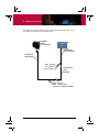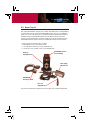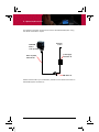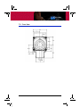
1
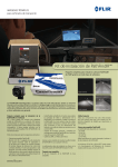
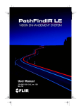
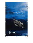
PathFindIR®
Aftermarket User Manual
334-0001-00-10, Version 130
October 2009
© 2009 FLIR Commercial Vision Systems, Inc.. All rights reserved worldwide.
No parts of this manual, in whole or in part, may be copied, photocopied,
translated, or transmitted to any electronic medium or machine readable form
without the prior written permission of FLIR Commercial Vision Systems, Inc.
Names and marks appearing on the products herein are either registered
trademarks or trademarks of FLIR Commercial Vision Systems, Inc. and/or its
subsidiaries. All other trademarks, trade names, or company names
referenced herein are used for identification only and are the property of their
respective owners.
This product is protected by patents, design patents, patents pending, or
design patents pending.
This equipment must be disposed of as electronic waste. Contact your
nearest FLIR Commercial Vision Systems, Inc. representative for
instructions on how to return the product to FLIR for proper disposal.
This document is controlled to FLIR Technology Level EAR 1. The information
contained in this document is proprietary and/or restricted and pertains to a
dual use product controlled for export by the Export Administration
Regulations (EAR). This document and data disclosed herein or herewith is not
to be reproduced, used, or disclosed in whole or in part to anyone without the
written permission of FLIR Systems, Inc. Diversion contrary to US law is
prohibited. US Department of Commerce authorization is not required prior to
export or transfer to foreign persons, parties, or uses otherwise prohibited.
FLIR Commercial Vision Systems, Inc.
70 Castilian Drive
Goleta, CA 93117
Phone: 1-888-747-FLIR (3547)
www.flir.com
Table of Contents
1 Warnings and Cautions
1.1 Cautions ................................................................................................................................. 1
1.2 General Information ......................................................................................................... 2
2 Introduction
2.1 Overview ................................................................................................................................ 3
2.2 Thermal Imaging Driver Vision Enhancement System .................................... 3
2.3 What is Thermal Imaging? ........................................................................................... 5
2.4 Vehicles that use PathFindIR Systems ................................................................... 5
2.5 PathFindIR Camera Model Numbers ...................................................................... 6
2.6 Full Feature PathFindIR Camera ................................................................................ 7
3 Getting Started
3.1 Using your PathFindIR Camera .................................................................................. 9
3.2 Initial System Startup ...................................................................................................... 9
3.3 Heater Element ............................................................................................................... 10
3.4 Automatic Shutter ......................................................................................................... 10
3.5 In Case of Difficulty ........................................................................................................ 10
3.6 Troubleshooting .............................................................................................................. 11
4 Caring for your PathFindIR System
4.1 Product Cleaning ............................................................................................................ 13
4.2 Temperature .................................................................................................................... 13
4.3 Maintenance .................................................................................................................... 14
5 Options and Accessories
5.1 Accessories ...................................................................................................................... 15
5.2 Aftermarket Installation Kit ....................................................................................... 17
5.3 Bench Top Kit .................................................................................................................. 19
6 Installation
6.1 PathFindIR System Installation ................................................................................ 21
6.2 Preparation ....................................................................................................................... 21
6.3 Installation ......................................................................................................................... 22
6.4 Installation Guidelines and Precautions .............................................................. 22
6.5 Installation Assistance ................................................................................................. 24
6.6 Mounting Assistance ................................................................................................... 24
7 Technical Data
7.1 Performance Specification ........................................................................................ 25
7.2 Side Views ......................................................................................................................... 26
7.3 Front View ......................................................................................................................... 27
334-0001-00-10, version 130
iii
iv
October 2009
1
Warnings and Cautions
1.1 Cautions
Caution!
This guide uses the term Caution to indicate a potentially hazardous situation,
which, if not avoided, may result in injury, damage to the vehicle or PathFindIR
system, or other property damage.
Caution!
The PathFindIR thermal imaging system is designed for commercial, over the
road, automotive applications. While many other applications are possible, you
must carefully consider additional protection and installation methods that
might be required for any given application. Mechanical, environmental and
electrical requirements should be evaluated to assure that the PathFindIR
system can be utilized with satisfactory results.
Do not operate any function that takes your attention away from safely
driving your vehicle.
Any function that requires your prolonged attention should only be performed
after coming to a complete stop. Always stop the vehicle in a safe location
before performing these functions. Failure to do so may result in an accident.
Consult your local and state driving regulations prior to installation.
In many states using active monitors in view of the driver is prohibited. Consult
your local and state driving regulations for laws and guidelines. User assumes
all risks and indemnifies the manufacturer from any liability.
Minimize display viewing while driving.
Viewing the display may distract you from looking ahead and may result in an
accident. Do not use the PathFindIR thermal imaging system as a substitute
for headlights or headlight assisted human vision during vehicle operation.
Use this product for mobile 12v applications.
The PathFindIR system is designed for the automotive 12 VDC power
environment and conforms to ISO 7637-2 requirements for transients and
disturbances on the typical automotive power system. If the PathFindIR system
is installed in applications other than commercial automobiles, additional
power conditioning or protection may be required.
When installing the PathFindIR camera, do not block the vehicle’s vents or
radiator panels.
Doing so may result in heat buildup, equipment breakage, and/or fire.
334-0001-00-10, version 130
1
1 – Warnings and Cautions
1.2 General Information
Caution!
The PathFindIR thermal imaging system is not intended to be used as the
primary navigation system. The PathFindIR system should not to be used as a
substitution for headlights or headlight assisted human vision during vehicle
operation. It should be used only as an aid to cautious night-time driving.
Do not open the camera body for any reason. Disassembly of the camera
(including removal of the cover) can cause permanent damage and will void the
warranty.
Operating the camera outside of the specified input voltage range or the
specified operating temperature range can cause permanent damage.
Do not image extremely high intensity radiation sources, such as the sun,
lasers, arc welders, etc.
The camera is a precision optical instrument and should not be exposed to
excessive shock and/or vibration. Refer to paragraph 7.1 “Performance
Specification” on page 25 for detailed environmental requirements.
Great care should be used with your camera optics. They are delicate and can
be damaged by improper cleaning. Refer to Chapter 4 “Caring for your
PathFindIR System” on page 13. Normal wear can be expected and scratches
and small pits in the window from normal wear will not usually adversely affect
the image displayed on the monitor.
Note
All thermal imaging systems are subject to export control. Please contact FLIR
for export compliance information concerning your application or geographic
area.
2
October 2009
2
Introduction
2.1 Overview
Congratulations! You have purchased one of the most sophisticated and
important instruments you will have on your vehicle. The FLIR PathFindIR
camera is a state-of-the-art thermal imaging system that will provide you with
excellent night visibility and situational awareness, even in absolute darkness.
The PathFindIR camera system is designed for simple, intuitive operation. The
PathFindIR camera is a sophisticated thermal sensor that converts thermal
content (heat) of a scene into a 2-dimensional image for display on a video
monitor inside your vehicle.
2.2 Thermal Imaging Driver Vision Enhancement System
The PathFindIR camera is designed to provide enhanced vision and better
situational awareness for the driver during normal night time driving and in
adverse weather conditions than with traditional headlights alone.
Many serious accidents occur at night because the driver is not able to see the
cause of the accident in time to prevent the collision. PathFindIR systems
directly address this problem, allowing drivers to see farther ahead on
nighttime roadways and identify potential problems earlier. Humans and other
warm blooded animals offer significant thermal contrast to driving
backgrounds and are easy to spot with the PathFindIR camera. The system
allows drivers to see without any additional lighting and provides real-time
imaging at any speed.
Different than visible light cameras, thermal imagers do not display reflected
light as seen with human eyes. Rather, thermal imaging cameras only 'see'
temperature differences which are converted into shades of grey, from black
to white. The PathFindIR camera in the standard configuration displays cold
objects as black and hot objects as white.
When using a thermal imager in darkness, the image is created based on
temperature differences of objects in the field of view, rather than reflected
light from headlights.
Because thermal imaging cameras only 'see' heat sources and not reflected
light, they are ideal to assist with driver vision and situational awareness for
oncoming obstructions such as animals, people, and other vehicles
334-0001-00-10, version 130
3
2 – Introduction
The above images show comparisons of typical night time driving compared to
using the PathFindIR thermal imager. The image on the left is from an ordinary
digital camera and shows the amount of visible light; the image on the right is a
thermal image created by the PathFindIR thermal imaging camera. Note the
PathFindIR camera is sensitive to warm objects, such as pedestrians, and
provides visibility over a much greater distance.
Some of the objects that are most critical for a driver to avoid are people and
animals. Because these objects are naturally warm, they are particularly easy
to see with the PathFindIR system and clearly stand out in the video image.
Although adverse conditions such as heavy fog will affect any driver vision
enhancement system, thermal imaging cameras such as the PathFindIR
camera have been shown to continue to provide useful information in
conditions of reduced visibility, such as haze and smoke. While the PathFindIR
4
October 2009
2 – Introduction
camera can assist drivers with detection of obstructions in the vehicle’s path,
thermal imagers should not be used as the sole vision method of the driver.
PathFindIR cameras are specifically designed for the harsh automotive
environment, with a hermetically-sealed external housing resistant to rocks,
sand, salt, and under-hood contaminants. Additionally, the wide operating
temperature range allows the PathFindIR camera to maintain high
performance in severe weather conditions.
2.3 What is Thermal Imaging?
With our eyes, we see visible light. With a thermal imager, we can see
infrared—a form of light just beyond the visible spectrum. Thermal imagers
show subtle differences in temperature; with a PathFindIR camera in the
standard configuration, warm objects appear white and cooler objects appear
black.
In addition to driver vision enhancement, FLIR's thermal imaging cameras are
used in a wide variety of applications—fire fighting, security, maritime, industrial,
and medical applications. They continue to be used by militaries worldwide to
navigate at night and in battlefield conditions. Over the last few years, volume
production of these systems has allowed FLIR to offer the same high
performance cameras designed for military use to the commercial market.
2.4 Vehicles that use PathFindIR Systems
Passenger Vehicles, Commercial Trucks, Buses, Construction, Mining, and
Recreational Vehicles - PathFindIR systems can increase the detection time
for hazards and reduce the probability of an accident—saving lives, property,
and profits.
Emergency Vehicles - The high speeds and degraded stopping distances of
Emergency vehicles increase the chance of an accident. PathFindIR systems
improve hazard detection at high speeds.
Commuter and Freight Trains - PathFindIR systems can reveal railway
obstructions at long ranges in complete darkness. This early detection
capability can significantly increase the warning time depending on the size of
the obstruction.
Heavy Construction and Mining Vehicles - For heavy equipment navigation,
PathFindIR systems improve awareness in conditions that render eyesight and
daylight cameras useless. The PathFindIR camera can see clearly through dust
and smoke, increasing safety for everyone on the job site.
334-0001-00-10, version 130
5
2 – Introduction
2.5 PathFindIR Camera Model Numbers
Standard PathFindIR Camera
334-0001-00
PathFindIR, 30Hz, NTSC
334-0001-00S
PathFindIR, 7.5Hz, NTSC
334-0001-00P
PathFindIR, 25Hz, PAL
334-0001-00PS PathFindIR, 8.3Hz, PAL
Full Feature PathFindIR Camera
334-0008-00
PathFindIR FF, 30Hz, NTSC
334-0008-00S
PathFindIR FF, 7.5Hz, NTSC
334-0008-00P
PathFindIR FF, 25Hz, PAL
334-0008-00PS PathFindIR FF, 8.3Hz, PAL
Note
All thermal imaging systems are subject to export control. Standard NTSC
(30Hz) and PAL (25Hz) units are subject to export restrictions and licensing
by the United States Government. Models with video frame rates at or below
9Hz do not require licensing but do require compliance with other export
requirements. Please contact FLIR for details concerning export compliance
for your application or geographic area.
6
October 2009
2 – Introduction
2.6 Full Feature PathFindIR Camera
The Full Feature PathFindIR camera is provided for OEMs and installers who
want to utilize custom features for their applications. The additional features
available on the Full Feature PathFindIR camera are selected and set via a LIN
(local interconnect network) communications channel. The white wire in the
standard PathFindIR System Cable (308-0159-00) provides the means to
send the LIN commands to the PathFindIR camera.
The additional custom features provided by the Full Feature PathFindIR camera
include the following:
•
•
Selectable color palettes—white hot, black hot, sepia, and rainbow
Selectable automatic gain control (AGC)—four AGC settings can be
selected
•
Additional signal outputs for 8-bit digital video data, clock signal, and sync
signal requires OEM cable 308-0152-00.
•
2× Zoom—The central part of the image is magnified twice its normal size.
•
LIN command to restore factory defaults
If you have purchased the Full Feature PathFindIR camera and need
information on these functions, contact your FLIR representative and request
the Electrical Interface Control Document (ICD) that describes the connector
interface and the proper formatting of the commands controlling these
additional functions. A non-disclosure agreement (NDA) is required in order for
FLIR to provide this document.
Note
The ICD describes the FLIR serial commands for the PathFindIR camera. An
aftermarket serial to LIN level shifter is required to convert the serial
commands LIN protocol and may further require client supported software
(for example an SDK). FLIR does not make recommendations for hardware
and cannot provide information or support for third party software use or
modification outside of the information provided in the ICD.
334-0001-00-10, version 130
7
2 – Introduction
8
October 2009
3
Getting Started
The thermal imaging core inside the PathFindIR camera is completely sealed
and extremely rugged. The camera has been qualified for operation in all types
of weather conditions over the specified operating temperature range and
includes an automatic window heater that will prevent icing under most
conditions.
3.1 Using your PathFindIR Camera
The PathFindIR camera is easy to use, but you should take a moment to
carefully read this section so you fully understand what you are seeing on your
display monitor. While the imagery you will see on the monitor may look like
black and white daylight video, it isn’t! A few tips on how to interpret some of
the imagery will help you to make the most of your system.
The camera automatically adjusts to changing scene conditions so no
additional camera control is necessary. Scenes with familiar objects will be
easy to interpret with some experience. The camera automatically optimizes
the image to provide you with the best contrast in most conditions.
The thermal imager inside the camera does not sense light like conventional
cameras; it senses heat or temperature differences. As you experiment with
the system during nighttime operation, you will notice variances in the “picture
quality”; this is normal. The camera senses small “differences” in apparent
radiation from the objects in view, and in the standard configuration displays
them as either white (or lighter shades of gray) for warmer objects, and black
(or darker shades of gray) for colder objects.
3.2 Initial System Startup
The PathFindIR camera requires a standard 12 VDC power source and a
connection to an external monitor to provide imagery. Make sure to test the
system prior to installation to assure the system is functioning properly. Be
sure to remove the protective window sticker prior to test and installation.
Upon initial power up you will hear a slight clicking sound. This click is the
internal image correction. This noise is the mechanical shutter assembly which
will cause the image to momentarily “freeze.” This noise and image freezing will
occur until the unit has reached a thermally stable temperature and
periodically thereafter. See “Automatic Shutter” on page 10.
334-0001-00-10, version 130
9
3 – Getting Started
3.3 Heater Element
The PathFindIR camera has a built-in heating element to stabilize the window
and prevent ice build-up in cold weather conditions. The heating element is
automatically turned on when the temperature of the window falls below 4ºC
and is tuned off when the temperature reaches 6ºC.
3.4 Automatic Shutter
The PathFindIR camera incorporates
an automatic image correction
feature via the internal calibration
shutter. This shutter will activate every
2 minutes or more frequently during
initial start up and large environmental
temperature changes. During this
function the image will be “frozen” for
approximately half a second.
The frozen image will display a small white box in the upper left corner of the
image during this calibration, as shown in the image above.
3.5 In Case of Difficulty
The PathFindIR camera comes with a 24 month limited warranty from the
date of purchase. DO NOT OPEN, MODIFY, or ALTER the PathFindIR camera or
accessories. Doing so will void any warranty and may cause system
malfunction, loss of performance, fire, or bodily harm.
The PathFindIR system is a highly sophisticated electronic imaging system.
Should the system fail for any reason do not attempt to fix the system or wiring
cables yourself. Check wiring connections, power input, video output. If system
is not performing please contact the manufacture at +1.888.747.3547 or
+1.805.964.9797 and ask to speak to the service department. You will need
the serial number of the unit to obtain a Return Material Authorization (RMA).
10
October 2009
3 – Getting Started
3.6 Troubleshooting
No Video but the system is running and has power supplied to it.
Place your ear next to the PathFindIR camera. If you hear the mechanical
shutter (clicking noise, see section 3.2 “Initial System Startup” on page 9) but
you are not getting an image, check the video connections. The PathFindIR
camera works with most standard NTSC or PAL monitors that have 75 ohm
input.
No Video, no clicking.
If video is not displayed and you do not hear a “clicking” sound from the
PathFindIR camera, check the power inputs. The camera runs on +6 VDC to
+16 VDC power through one of the optional power/video cables. If this voltage
range is not adhered to the unit will not function and may be damaged.
The image is cloudy or hazy, or the window has fog or ice built up.
The PathFindIR camera is equipped with an automatic heating element which
turns on at cold temperatures. The heater requires a few moments to stabilize
the window. Once the window is thermally stabilized the heating element will
turn off automatically.
The image has "lines" or screen door appearance.
Check to see if the image “freezes” or if you hear a mechanical “clicking noise”
from the PathFindIR camera. If you do not see the image freeze momentarily
(this may take a few minutes), the internal shutter may be damaged. Contact
the manufacturer.
The image is shaky.
Check your mounting. The PathFindIR camera does not incorporate image
stabilization and must be mounted securely.
Image is dim.
Check your monitor and video connections. It is recommended that you use
separate power supplies for the PathFindIR camera and the local display
monitor to make sure you have clean uninterrupted power. Also, verify the
PathFindIR camera is connected to the 75 ohm input on the monitor. The
image may be dim if the camera is connected to an input that requires a
different impedance.
334-0001-00-10, version 130
11
3 – Getting Started
The image is dark and no objects are seen.
Recycle the power and see if you get the “Splash Screen” (as seen below) on
the display monitor. If you get the Splash Screen but no image afterwards (only
a black screen), check to make sure that the window is clear of all obstructions
(refer to the maintenance section for information on window cleaning). If you do
not see the Splash Screen, check the power input and video output.
If you see the Splash Screen but no image afterwards, it is possible the
mechanical shutter is stuck in the on position. Contact FLIR customer service
for additional help.
Figure 3-1: Startup Splash Screen
12
October 2009
4
Caring for your PathFindIR System
4.1 Product Cleaning
Caution!
Do not open the camera body for any reason. Disassembly of the camera
(including removal of the cover) can cause permanent damage and will void the
warranty.
Your PathFindIR camera images through an infrared transparent window. This
window is designed for the harsh automotive environment of normal driving,
but may require occasional cleaning. FLIR Commercial Vision Systems, Inc.
suggests that you clean the window of the PathFindIR camera when image
quality degradation is noticed or excessive contaminant build-up is seen on the
window.
Note
During normal use the camera window may become scratched or develop
small pits. These usually will not cause a noticeable degradation of the
displayed image.
The camera housing has a durable coating and the rugged protective window
is designed to withstand normal cleaning. Rinse the camera housing with low
pressure fresh water to keep it clean. If the front window of the PathFindIR
camera gets water spots, wipe it with a clean soft cotton cloth dampened with
fresh water. If the window requires further cleaning, use a soft moist cottonbased cloth with isopropyl alcohol or dish soap.
Do not use abrasive materials, such as paper or scrub brushes as this will
possibly damage the window by scratching it. Only clean the window when you
can visually see contamination on the surface.
4.2 Temperature
The PathFindIR camera has an operating temperature range of -40 to 80oC.
Choose an installation location so that the PathFindIR camera is not subject to
temperature extremes that exceed this range.
334-0001-00-10, version 130
13
4 – Caring for your PathFindIR System
4.3 Maintenance
If you have problems do not attempt to repair the PathFindIR system yourself.
The PathFindIR camera is a water-tight sealed unit and can not be opened or
serviced in the field. Consult your installation dealer or FLIR Systems Inc. for
repair information.
If the camera will not produce an image, check the video connection at the
camera and at your display monitor. If the connectors appear to be properly
engaged but the camera still does not produce an image, have an authorized
service representative make the appropriate repairs.
Front
Window
Figure 4-1: Front Window
Caution!
Improper care of the camera window can cause damage to the anti-reflective
coating, degrade the camera’s performance, and void the camera warranty.
14
October 2009
5
Options and Accessories
5.1 Accessories
Camera options and accessories are subject to change. Refer to the FLIR web
site http://www.flir.com or contact your local dealer to obtain up-to-date
information regarding available accessories such as mounting kits, monitor
options, cables, and accessories.
PathFindIR System Cable: 308-0159-00
The standard 20-foot system cable ensures a sealed connection to the
PathFindIR camera—a requirement for harsh vehicle environments. The cable
has a sealed PathFindIR connector at one end; two power leads (red and
black), a communications lead (white), and a BNC video connector at the other
end.
To Camera
Video output
White
Communications
Black
12 VDC (-)
Red
12 VDC (+)
For standard operation the white communications lead can be clipped off or
dressed back and secured out of the way—it is not used. Refer to paragraph
2.6 “Full Feature PathFindIR Camera” on page 7 for a description of
applications that utilize the PathFindIR camera communications feature.
334-0001-00-10, version 130
15
5 – Options and Accessories
PathFindIR Universal Mounting Bracket: 261-1470-00
The Universal Mounting Bracket is shown below with the PathFindIR camera
inserted, but not secured. The bracket has mounting holes on all four sides
providing flexibility in choosing a mounting location. The camera has two pivot
posts that are inserted into slots allowing about 45° of adjustment. A kit of
mounting hardware is provided with the bracket. There are two M4 × 0.7
metric screws with washers and lockwashers to secure the camera to the
bracket and four ¼ × 20 bolts and lockwashers for attaching the bracket to
the vehicle.
Universal Mounting Bracket
¼ × 20 threaded insert
sixteen places
Screw slot
Pivot post
PathFindIR camera
16
October 2009
5 – Options and Accessories
5.2 Aftermarket Installation Kit
The FLIR Aftermarket Installation Kit, part number 421-0029-00, is made
available to facilitate installation in most vehicle applications and includes a
video monitor, cables, and mounting hardware. The kit will work with any
PathFindIR camera, which while included and shipped in the kit must be
selected and purchased separately. The kit contains:
•
•
•
•
•
•
Universal Mounting Bracket and hardware: 261-1470-00
PathFindIR System Cable: 308-0159-00
Safety Vision 7” Monitor with Mounting Bracket and Sun Shield: 4105734
Video Interface Cable: 4105735
PathFindIR User Manual and CD ROM (not shown)
PathFindIR Camera (chosen and purchased separately)
Mounting bracket
Monitor
Video
interface cable
PathFindIR
interface cable
PathFindIR camera
(purchased separately)
Any of the components supplied in this kit can also be purchased separately.
Note that the monitor part number 4105734 will require the video interface
cable part number 4105735 to operate properly.
334-0001-00-10, version 130
17
5 – Options and Accessories
The following schematic shows how to connect the PathFindIR system using
the cables in the Aftermarket Installation Kit.
PathFindIR
Camera
(sold separately)
4105734
Monitor
Monitor Cable
(part of 4105734)
System Cable
308-0159-00
green - not used
red - power (+)
black - power (-)
Video Interface
Cable
4105735
red - power (+)
black - power (-)
white - communications
(not used for standard installation)
18
October 2009
5 – Options and Accessories
5.3 Bench Top Kit
The optional FLIR Bench Top Kit, part number 421-0027-00, is made available
for those who want to operate the PathFindIR system from a 110/240VAC
power source, for lab testing or for applications where standard AC power is
available. Using the PathFindIR system with the Bench Top Kit requires a
monitor (not supplied) having a 75-ohm video input. The kit will work with any
PathFindIR camera, which must be purchased separately. The kit contains:
•
•
•
•
Bench Top Mounting Bracket: 261-1418-00
PathFindIR Bench Top Cable: 308-0142-00
110/240 VAC to 9VDC power supply: 206-0001-20
110 VAC Line cord for 9VDC power supply: 208-0004-02
PathFindIR camera
(not included)
Bench top
mounting bracket
Power supply
206-0001-20
PathFindIR
bench top cable
Line cord
208-0004-02
Any of the components supplied in this kit can also be purchased separately.
334-0001-00-10, version 130
19
5 – Options and Accessories
The following schematic shows how to connect the PathFindIR system using
the cables in the Bench Top Kit.
PathFindIR
Camera
(sold separately)
Bench Top Cable
308-0142-00
AC Power
Source
Power Supply
206-0001-20
BNC Video out
Please contact FLIR or your local dealer/installer for the latest information on
PathFindIR system accessories.
20
October 2009
6
Installation
6.1 PathFindIR System Installation
Caution!
The PathFindIR thermal imaging system is designed for commercial, over the
road, automotive applications. While many other applications are possible,
each user should carefully consider additional protection and installation
methods that might be required for any given application. Mechanical,
environmental, and electrical requirements should be evaluated to assure that
the PathFindIR system can be utilized with satisfactory results.
The PathFindIR camera is a compact, sealed imaging system that fits easily
behind vehicle grilles and in other compact locations. It includes an internal
heater to keep the lens clear in icy conditions, and delivers superior image
quality. It can be ordered as a camera module alone, with a commercial grade
cable, mounting bracket, or as part of a complete installation kit.
The PathFindIR camera must be mounted in a location where it is not
obstructed by the windshield or other glass materials. Although glass is
transparent to the human eye, it is opaque in the infrared spectrum.
The PathFindIR should be installed by an installer or dealer trained by FLIR
Commercial Vision Systems, Inc. If one is not available in your area we
recommend that you use a reputable car audio/video installation shop that
specializes in mobile video system integration. The wiring and installation
requires special care and integration techniques. Improper installation may
result in damage to the camera and may void the warranty.
Some modifications to the vehicle’s exterior may be required, as well as
integration into various display monitor units, including factory LCD or
aftermarket multi-functional units.
6.2 Preparation
The PathFindIR standard 20-foot system cable has two open power leads—red,
12 VDC (+); black, 12 VDC (-)—for connecting to a power source of 6 –16 VDC.
The cable also includes a white wire and a BNC male adapter. The white wire is
not used for standard installations. It can be clipped off or dressed back and
secured out of the way. This wire is only used for Full Feature camera
installations as described in paragraph 2.6 “Full Feature PathFindIR Camera”
on page 7. Refer to the model number to determine your specific PathFindIR
camera analog video output format. See “PathFindIR Camera Model Numbers”
on page 6.
334-0001-00-10, version 130
21
6 – Installation
It is recommended that power to the monitor be supplied separately from
power to the PathFindIR camera to assure clean (low noise) power to both
components. Otherwise the video image may appear to have interference,
ghosting, or undesirable video artifacts.
6.3 Installation
Caution!
Before wiring the camera, disconnect all power from the battery. Failure to do
so may result in shock, bodily harm, or damage to the vehicle, camera, or
accessories.
Installation using incorrect connections may result in system malfunction or
risk of shock. FLIR Commercial Vision Systems, Inc. recommends the standard
20-foot system cable for proper installation (refer to paragraph 5.1
“Accessories” on page 15). This cable is sealed and provides two power input
leads, a communications lead (used only for Full Feature camera installation),
and video output via the connected BNC adapter.
The proper mating connector must be used when installing the PathFindIR
camera. The use of other connectors may result in damage to the camera that
is not covered by the limited product warranty.
The standard 20-foot system cable has a BNC connector for video output. You
may need to purchase connectors/converters to connect to aftermarket or
factory-installed video monitors.
6.4 Installation Guidelines and Precautions
Caution!
Supplying power to the unit outside of the recommended and stated values will
result in system malfunction and void the warranty. This may also result in
excessive heat build up, shock, or fire.
Note
For standard installations, the white communications wire is not used. If you
are installing a Full Feature camera system, refer to paragraph 2.6 “Full
Feature PathFindIR Camera” on page 7.
Do not splice cables or tap into existing cables for power or video. Doing so
may result in shock, fire, or damage to electrical system/equipment. Power
22
October 2009
6 – Installation
connections should be made to the fused side of the vehicle’s power
distribution block.
Do not install in areas where the unit will hinder vehicle operation, i.e. radiator,
steering, headlights, braking systems. Doing so may interfere with the vehicle's
operation and cause an accident.
Do not install in areas of high moisture, dust or air intake paths. Doing so may
hinder the performance of the PathFindIR unit and cause image degradation
or window damage.
Use only authorized parts and accessories. Doing so helps assure proper
mounting and connectivity and limits external issues associated with poorly
secured mounting and wiring.
Disconnect the negative (-) battery terminal prior to installation.
Connect the unit to the vehicle power distribution block using an available fused
(2 amp) connection. Be sure to connect each lead to the correct polarity (redpositive and black-negative).
Caution!
The PathFindIR system is designed for the automotive 12 VDC power
environment and conforms to ISO 7637-2 requirements for transients and
disturbances on the typical automotive power system. If the PathFindIR system
is installed in applications other than commercial automobiles, additional
power conditioning or protection may be required.
Be sure to securely mount the system to assure reliable connections and
stable system performance.
Record the serial number, date of purchase, location of purchase and keep this
record in a safe place.
Do not mount a display monitor where it will distract the driver or adversely
affect the driver’s vision.
334-0001-00-10, version 130
23
6 – Installation
6.5 Installation Assistance
FLIR offers the Aftermarket Installation Kit which is suitable for many
applications. Refer to paragraph 5.2 “Aftermarket Installation Kit” on page 17
for more information about installing the camera with the kit.
If your company has applications utilizing a large number of PathFindIR
cameras on a specific vehicle please contact FLIR Commercial Vision Systems,
Inc. directly to discuss your needs.
6.6 Mounting Assistance
The following are some general guidelines which will assist your professional
service and installer with good mounting positions and connections.
The PathFindIR camera is a thermal imaging system. As such, it will not “see
through” windows or obstructions. The camera should be mounted outside the
vehicle's cabin (interior) and in such a location to assure a similar driving field
of view as normal headlights and human vision.
Carefully position and adjust the camera mounting so that the largest area of
interest (road and roadside) are in the field of view. If the camera is pointed too
low, the range will be limited. If the camera is pointed too high, too much of the
sky will be in the field of view limiting the usable information and reducing the
effectiveness of the PathFindIR AGC (automatic gain control) function.
Caution!
Contact your vehicle manufacture to assure that your mounting location does
not affect any sensors found in bumpers or grilles (such as for air bag
deployment devices). Mounting the PathFindIR system components should
never interfere with the mechanical or electrical components, or airways to
maintain vehicle performance or operations.
FLIR Commercial Vision Systems, Inc. is not liable for any modifications made
to the vehicle's body, or aftermarket parts. Owner assumes all risk when
modifying vehicles body, frame, grille, or any other structure. Care should be
taken when drilling or cutting into parts.
Mounting should be performed by a FLIR-authorized service center or
professional installer of automotive aftermarket equipment. Many shops
familiar with rear vision cameras will be able to assist in the mounting and
location of the PathFindIR system, as well as proper display monitor mounting
and integration.
24
October 2009
7
Technical Data
7.1 Performance Specification
Thermal Imaging Performance
Sensor type
Uncooled microbolometer
Field of view
36° h x 27° v
Spectral band
8 - 14 μ
Resolution
320 x 240 pixels
Time to Image
< 2 sec.
Focal Length
19 millimeters
Outputs
Video
NTSC or PAL
Connector types
12-pin automotive connector for power in, video out
Frame Rate
30-Hz for NTSC Video, 25 Hz for PAL video
Note: Hz is equivalent to 7.5-Hz for NTSC Video, 8.3 Hz for PAL video
(< 9 Hz Export Compliant)
frames per second
Power
Power requirements
12 Vdc nominal (range 6V to 16V)
Power consumption
2 Watts (nominal)
6 Watts with window heater turned on
Environmental
Operating temperature -40º C to +80ºC
Impact protection
High-impact resistant window with heating element
Weather Resistance
Hermetically sealed, pressurized enclosure
For additional information, contact FLIR.
Dimensions and Weight
Dimensions (Width ×
Height × Length)
58 mm × 57 mm × 72 mm (2.3” × 2.2” × 2.8”)
excluding connector
Connector adds 25.7 mm to height
Weight
less than 0.4 kg (0.88 lb.)
Mounting Points
one per side, M4 × 0.7
two 6 mm screws required
334-0001-00-10, version 130
25
7 – Technical Data
7.2 Side Views
26
October 2009
7 – Technical Data
7.3 Front View
334-0001-00-10, version 130
27
7 – Technical Data
28
October 2009
Santa Barbara
Portland
CVS World Headquarters
FLIR Corporate Headquarters
FLIR Systems, Inc.
70 Castilian Dr.
Goleta, CA 93117
USA
PH: +1.888.747.FLIR
(+1.888.747.3547)
FLIR Systems, Inc.
27700A SW Parkway Ave.
Wilsonville, OR 97070
USA
Netherlands
CVS Eurasian Headquarters
FLIR Commercial Vision
Systems B.V.
Charles Petitweg 21
4847 NW Teteringen - Breda
The Netherlands