1
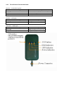
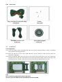
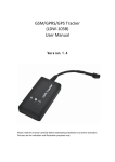
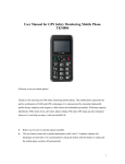
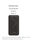
GSM/GPRS/GPS Tracker
(LDW-101-B)
User Manual
Version 1.0
Chapter I Preface
1. 1 General
LDW-101 represents the perfect combination of GSM, GPRS and GPS technologies.
This model, with precise dimensions and compact appearance, expresses the
advanced workmanship in the GSM and GPS field and is the typical design combing
communication products and GPS services.
As a professional security and positioning company, we will provide you with more
and better products and services. Before use, please spend several minutes reading
this user’s manual in order to understand operation details and obtain better
services.
1.2 Notices
1) Please read carefully this user’s manual and always use correct operation
methods to prevent any possible errors.
2) This user’s manual is for reference only. If some contents and operation steps are
inconsistent with those for the actual product, the latter will prevail.
3) The defaulted password of this product is 0000.
GPS Tracker LDW-101 is a perfect combination of GSM, GPRS and GPS. Small size
and simple appearance are the typical design of the combination of telecommunication
products and GPS positioning products. Advanced technology and craft in GSM and
GPS area are embodied in this product.
Chapter II About the Device
LDW-101 is remote vehicle positioning device comprising GPS and GSM/GPRS
modules. Based upon the GPS satellite, it shall offer you precise positioning
information on dynamic conditions. The remote vehicle positioning device shall send
longitudinal and latitudinal coordinates to the authorized cell phone, which can be
utilized by you to position and manage your own vehicles.
2.1 Major Functions of the Product
Vehicle Positioning and Tracking
Real-time polling and sending back GPS positioning information (which contains longitude,
latitude, speed and direction) and the vehicle information to the service platform
www.gpsph.com, displaying vehicle’s real-time condition of the vehicles.
Trace Playback
Related information such as the passed trace, speed and time and so on of the vehicles in the
past period can be replayed.
Historical Data Backup
In the data base, vehicle’s driving time, trace and speed etc. can be conserved in one day or
more. In order to keep the response speed of the data service, the system shall automatically
transfer the current database into historical database at regular intervals.
Anti-burglary and Anti-robbery
In case of emergency situation, driver can press the SOS button for sending the message to
pre-set number to ask for help.
Message Dispatching
If necessary, the administrator can send messages to the driver’s mobile-phone to dispatch,
direct the vehicle.
2.2 Components
2.2.1 Built-in GPS module and GSM module
Instructions: the red line connects to the power positive; the black line connects to the
power negative.
2.2.2 Internet Service Center: www.gpsph.com.
2.3 Product Features
● Individual or fleet GPS polling
● Worldwide use
● Supports GSM frequencies 900/1800/1900MHz or 850/900/1800/1900MHz
● High-sensitivity, latest technology and the most advanced GPS chip
● Can accurately position even if with weak signal
● Can work effectively in limited space such as the remote and narrow places;
● compact size, easy for hiding
● Low energy consumption
● Fast signal capturing
● supports two modes: text message polling and GPRS trace tracking
● Alarm function
2.4 Product Specifications
2.4.1 Technical specifications
GSM FREQUENCY
900/1800/1900MHz or 850/900/1800/1900MHz
GPS CHIPS
SIRF Star III
GPRS
Class 12, TCP/IP build in GSM MODULE
GPS SENSITIVITY
-159dBm
GPS ACCURACY
10m(2D RM)
GSM ACCURACY
50-200m
SPEED ACCURACY
0.1m/s
COLD STATUS
-38s
WARM STATUS
-32s
HOT STATUS
-2s
MAXIMUM ALTITUDE
18000m
HIGHEST SPEED
515m/s
ACCELERATION OF GRAVITY
SIZE
﹤4g
90.00(L) x 45.0(W) x12.0(H) mm
WEIGHT
45g
2.4.2 Others
WORKING TEMPERATURE
-20--+70℃
HUMIDITY
20%---80%RH
VOLTAGE
7—30v DC
CURRENT
STUANDY AVERAGE CURRENT
~60mA(12v DC)
<80MA
LED
LED indicate GPS、GSM working status or other condition
~35mA(24v DC)
2.4.3 The indication of the terminal state
Red LED------Power/Running-state
The state of the light
Meaning
Always light
Indicate the power supply, normal working state
Flash
Abnormal working state
No light
Out of power or internal fault
BlueLED------GPS Signal
The state of the light
Meaning
Always light
GPS signal received normally
No light
GPS signal close
Green LED------GSM Signal
The state of the light
Meaning
Always light
GSM 信号接收正常/有电话打进
No light
未搜到 GSM 信号
2.4.4 Accessories
2.5 Installation
2.5.1 Preparation
2.5..1 Check the product: open the package, and check the terminal model and fittings. If there is something
wrong, please contact the distributor.
2.5.2 Select the SIM card: it must insult a GSM SIM card, and the selection of SIM card must follow the
distributor's suggestion.
2.5.3 Install the SIM card. Firstly, open the cover of the terminal, remove the cover on the slot for SIM card;
secondly, insult the card into the slot with the metal side in the bottom; thirdly, fasten the slot (do as the
following instruction); finally, recover the terminal and lock the shell tightly with three screws.
Tips:
Don't insult the terminal SIM card up-side-down.
You must open the GPRS function provided by the terminal SIM;
If your SIM card has been setup, but it requires you to input SIM PIN, please close the SIM PIN
function under the instruction written in the user manual.
Make sure the sufficient money to pay for the terminal SIM card charge
Check the GPRS network connection with your mobile phone.
2.5.2 The selection and installation of the terminal
This terminal is a product with GPS polling, a kind of high-tech product; you'd better to install it with the
help of professional companies or workers authorized by the distributor.
Please install it according to the following order, don't revise it, or supply power for the terminal.
There are two ways to install the terminal: hidden installation and open installation. Hidden installation is
suitable for the application of the terminal in the specialized vehicle. While open installation is suitable for the
adoption of the terminal in the provisional vehicle.
2.5.1 The hidden installation should be completed by the professional institution authorized by the distributor.
1) To avoid the thief’s destruction, the terminal should be installed in a hidden place. Suggestions are as
follow:
Hidden beneath the decoration board below the front windshield.
Hidden around the front panel (with a surface made of non-metal materials)
Hidden beneath the decoration board under the back windshield.
2) Don’t put the terminal together with the emission sources, such as the parking radar system, alarms and
other vehicle-carried communication terminals.
3) You can fix the terminal with the cable tie, or glue it with wide strong sponge double-sided tapes.
4) As there are GSM and GPS antennae furnished inside the terminal, it must make sure the reception side of
GSP upward (facing the sky), besides there is no shelter caused by metal articles.
Attention:
If there is a metal insulation or a heating level glued in the windshield, it will reduce the
efficiency of GPS signal reception, and lead to change the installation position of the terminal
due to the malfunction of GPS.
2.5.2 AS for the open installation, at first it should glue the soft robber magnet (in the fitting picture) on the
decoration below the front windshield; then put the terminal on the magnet and fix it.
Attention:
If you have no soft robber magnet, please purchase after connect with the distributor.
Installation
map:
Installation steps (caution: the following installation should be made without power supply,
otherwise it will be dangerous)
Wire for cutting off oil of the tracker
Yellow wire connects the relay feet 86; 85 feet to 12 V DC anode, 87 feet and 30 feet in series in
the supply oil circuits.
Wire for cutting off circuit of the tracker
White wire connects relay feet 86; 85 feet to 12 V DC anode, 87 feet and 30 feet are in series in
the supply power circuits.
2.6 The cable connection of the terminal
2.6.1 The standard power supply is 7V-30V; the red line connects to the power positive, while
the black line connects to the power negative.
2.6.2 The negative end should connect the ground or the metal alone, don't connect with other
ground cord.
2.6.3 After connecting the power cord, please pull the power cord plug near the terminal, and
supply power for it after installation.
2.6.4 As for the hidden installation, the connection cords for the power should be the main
power cord provided by the original manufacturer (in the fitting pictures), the red end connects
with the fuse box (contains 2A FUSE), which can avoid the short circuit and over current.
2.6.5 As for the open installation, the connection cords for the power should be the lighter
power cord provided by the original manufacturer (in the fitting pictures), the lighter, which has
2A FUSE can avoid the short circuit and over current.
Remind:
Please contact your distributor if you don’t have the lighter power cord.
2.7 Terminal working
2.7.1 Starting up:The terminal automatically starts up with power connecting, the red indicator
on means the power supply normally. Working normally, the red indicator will keeps on; the
blue GPS indicator will always bright means GPS polling standy already; the green indicator
shows GSM connecting successfully.
2.7.2 Working exception: after working for some time, the red indicator light flashes, blue GPS
Light off, means that GPS is off or failure, GSM indicator not on shows that GSM fails to receive
signal, please see the troubleshooting method to eliminate the problem.
2.7.3 Powering off: Pull the plug, and the terminal will be powering off after cutting off the
electricity.
2.8 Side key function
In normal light conditions, press the side button 3S, then the current location information
will be sent back to the center number
2.9Terminal failure recovery
2.9.1 Disconnecting between terminal and service center:
Firstly, please checks the three lights of terminal, if there is no conditions for observation, please call the
terminal SIM card number using a mobile phone, and according to instruction to judge the terminal state.
● If not connected, and suggests that the terminal cannot be connected or temporarily out of service.
Terminal may not be covered by the GSM signal, or in weak for signal such as the basement, please drive to
some place covered by GSM net.
● If not connected, and suggests insufficient funds of the terminal or shut down. Please recharge for this SIM
card.
● If it is connected and there is the "beep" sound.
Terminal SIM card is installed correctly and has remaining, please contact the operator of this SIM card to
check whether the card has opened GPRS ; or you can also use the phone browser, enter your favorite Web
site to see whether can open the Web page. Otherwise, it should not open GPRS service, please contact
network operators to open it for you.
● If not connected, and the terminal has turned off
At this point, must call vehicle back to check the working status of the terminal, dealing with the following
steps:
a) Check the red indicator, if not light, check the terminal connections at the fuse or power supply terminal; it
also can be measured with a millimeter to check the 2P main power line voltage, if the voltage is normal,
then please remove the terminal machine and send it back to the original dealer for maintenance service.
b) If the red power indicator is constantly on, green light for GSM is not on, then please check SIM card is
properly installed, if the installation has no problem and please change for another SIM card to use.
2.9.2 When the GPS signal reception is abnormal:
Please drive to a more open area to locate. It takes one or two minutes for the first time. If it does not
locate, please check the installation location of the terminal, which is usually installed in the place
without metallic shelter.
2.9.3 When the GSM signal reception is abnormal:
Please check whether the terminal's SIM card is correctly installed; or the place may not be covered by
GSM signal (such as in the basement), please drive to the places covered by signal.
2.9.4 At the moment connecting power:
If the red light is not on, check the insurance of power lines to see whether the wire is fused, if it is fused,
please contact your dealer for the same model FUSE and exclude internal fault of the terminal before
reuse.
2.10 Location queries
Global Services Platform Website: www.gps288.com
2.10.1 Operation
●Setup of Center Number
Set the center number by means of SMS through mobile phone. After the setup is successful, then
the mobile phone sending the SMS will receive the “config OK” response message from the
terminal.
Format: #710# center number # user password # user password #
For example: #710#134xxxxxxxx#0000#0000#
Note: All alarming information thereafter including SOS, low power, electronic fence, etc will be
returned to such number.
● Setting the pre-stored phone numbers(SMS center number):
Before setting Center number, the device will respond any mobile phone’s command, after successfully setting,
the device will respond no other number except the center number. 9 numbers can be pre-stored at most.
Format:#711#phone number#password#serial##
For example:You want to set three stored numbers
#711# Phone number 1#0000#1## ---------------The first number
#711#phone number 2#0000#2## ----------------The second number
#711#phone number 3#0000#3## ----------------The third number
Only one phone number can be pre-sorted per time, as above mentioned three numbers need to send SMS
three times separately. GPS tracking device received an order and confirm that the password is correct, and the
new numbers will replace the existing serial number location, and after that send confirmation to the
sender….CONFG OK
● SOS button(Emergency call button):
In case of emergency, please press SOS button over 3 seconds, an emergency will be reported SMS
center number with current location, and call the pre-stored numbers in turn.
● Change the password
Format: #770# new password # old password ##”
Example: #770#1111#0000##
After successful sending, the GPS tracker will return a message “CHANGE OK”. And the user
password would change into: 1111.
Remind: Now all set-up format’s password change accordingly into “1111”
● Geo-fence set up
Set up a geo-fence for the unit to restrict its movements within a district. The unit will send the
message to the authorized numbers when it breaches the district.
Tips: Only settings pre-stored number successfully, this function can be realize
Format: #750#radius (5 digits)#sampling interval (minutes)#password # #
Choose current location as basic reference point; carry out above mentioned format to open
fortified state. In the fortified state get the GPS data according to the time and compare it with
fortified data. If out of maximum fortified range, it will dial-up or set alert message to users based
on alert setting. If the setting is correct, the module will reply CONFIG OK to the setting phone,
and if the password is wrong, it will reply PASSWORD ER.
For example: #750#500#5#0000##
After the setup is successful, a fence with the radius of 500 meters will be set up, and the setting
mobile phone will receive a returned SMS “config ok”. Then, when the ward leaves this area, the
terminal will send the alarming information “OBJECT OUT” of being out of the fence to the center
number.
● Cancel geo-fence
Format: #760#password##
Example: #760#0000##
After the terminal receiving this command, all fence settings will be cancelled, and return a SMS
“CONFIG OK”. The device will also reply “PASSORD ER” when the format’s password wrong.
●Setup of Server Address
Format: #803# Fixed IP address# port number#4-digit password##
This command is used to set GPRS center server address, which could be fixed IP number. After the
setup is successful, the module will send a reply with ‘&803&successful setting&&’ or
‘&803&PASSWORD ER&&’ if the password is wrong.
Example: #803#116.255.144.138#8479#0000##
Setup via domain name:
Example: #803#www.gps009.com#8479#0000##
● Set APN Command
Create the SMS “802#APN letters or digits, 4-20 bits # Log user name letters or digits 4-20 bits in
# Log password letter or digits 4-20 bits in # terminal password 4 bits ##” and send it to the
terminal; after executing this command, the terminal will automatically restart and connect to
GPRS with APN set. As the PAN letter as “0”, the APN defaulted as CMNET; and when the log user
name and log password be set as “0” means disuse user name and password.
Command example 1: #802#0#0#0#0000##
Terminal’s APN be set up as CMNET
Command example 2: #802#CCDLEN#QIUXIA.21#RX0000#0000##
After this command is executed, APN will be CCDLEN; the login user name is QIUXIA.21 and login
password is RX0000.
Note: The default APN of this product is CMNET.
● Regular Upload Interval Setup
The defaulted factory upload interval of this device is 2 minutes for getting the point and 10
minutes for uploading one piece of positioning information. The user may change such parameter
according to actual demand.
Format: # command number 730# Sampling interval # Pieces of uploads # User password ##
For example: 730#20#4#0000##
Note: The parameter “20” indicates getting one point every 20s; after getting points accumulatively for 4 times,
upload one piece of positioning information with the upload interval as 20*4=80s. The user may change this
parameter as the case may be.
●Auxiliary Functions:
(1)#901## Command of reading user parameters;
(2)#902## Command of reading GPRS parameters
(3)#903## Restart command
(4)#904## GPRS connection command
(5)#905## GPRS disconnection command
2.10.2 Location query
● SMS query
Sending SMS Format:666+Password(Defaulted Password:0000)
For example: Shenzhen City, Guangdong, 20 meters near the Lau Sin Wah Kee Hakka food hall north of 83
degrees within distance of 9 meters (22 5847,113 9448)
(Figures in brackets denote the target latitude and longitude of the current location) if the terminal don’t
receive the GPS signal of Latitude and longitude (-000.000. 000.00)
Please enter 22.5847, 1139,448. at website: http://earth.google.com (GOOGLE MAP) for querying location.
● Cut oil supply by SMS
Format: 233+password
Example: 2330000
After sending command successfully, the tracker will return a message “SET OK” and cut oil supply of the
vehicle.
● Cut power supply by SMS
Format: 232+password
Example: 2320000
After sending command successfully, the tracker will return a message “SET OK” and cut power supply of the vehicle.
● Resume power supply and oil supply by SMS
Format: 230+password
Example: 2300000
After sending command successfully, the tracker will return a message “SET OK” and resume power supply and oil supply
of the vehicle.
● Platform query
Step one:Log on our service website www.gpsph.com
Step two:Click the terminal name, the map will automatically indicate terminal’s location
Remark:If you already have the user name, you could login our service website directly,
if not, please call your distributor for opening user account.
Open your Internet Explorer, and enter our service website address, then fill in your
user name & password, and click “Login”.
Our distributor will provide you the “Service Platform User Manual” for your reference.