1
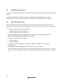
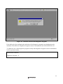
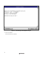
To our customers, Old Company Name in Catalogs and Other Documents On April 1st, 2010, NEC Electronics Corporation merged with Renesas Technology Corporation, and Renesas Electronics Corporation took over all the business of both companies. Therefore, although the old company name remains in this document, it is a valid Renesas Electronics document. We appreciate your understanding. Renesas Electronics website: http://www.renesas.com April 1st, 2010 Renesas Electronics Corporation Issued by: Renesas Electronics Corporation (http://www.renesas.com) Send any inquiries to http://www.renesas.com/inquiry. Notice 1. 2. 3. 4. 5. 6. 7. All information included in this document is current as of the date this document is issued. Such information, however, is subject to change without any prior notice. Before purchasing or using any Renesas Electronics products listed herein, please confirm the latest product information with a Renesas Electronics sales office. Also, please pay regular and careful attention to additional and different information to be disclosed by Renesas Electronics such as that disclosed through our website. Renesas Electronics does not assume any liability for infringement of patents, copyrights, or other intellectual property rights of third parties by or arising from the use of Renesas Electronics products or technical information described in this document. No license, express, implied or otherwise, is granted hereby under any patents, copyrights or other intellectual property rights of Renesas Electronics or others. You should not alter, modify, copy, or otherwise misappropriate any Renesas Electronics product, whether in whole or in part. Descriptions of circuits, software and other related information in this document are provided only to illustrate the operation of semiconductor products and application examples. You are fully responsible for the incorporation of these circuits, software, and information in the design of your equipment. Renesas Electronics assumes no responsibility for any losses incurred by you or third parties arising from the use of these circuits, software, or information. When exporting the products or technology described in this document, you should comply with the applicable export control laws and regulations and follow the procedures required by such laws and regulations. You should not use Renesas Electronics products or the technology described in this document for any purpose relating to military applications or use by the military, including but not limited to the development of weapons of mass destruction. Renesas Electronics products and technology may not be used for or incorporated into any products or systems whose manufacture, use, or sale is prohibited under any applicable domestic or foreign laws or regulations. Renesas Electronics has used reasonable care in preparing the information included in this document, but Renesas Electronics does not warrant that such information is error free. Renesas Electronics assumes no liability whatsoever for any damages incurred by you resulting from errors in or omissions from the information included herein. Renesas Electronics products are classified according to the following three quality grades: “Standard”, “High Quality”, and “Specific”. The recommended applications for each Renesas Electronics product depends on the product’s quality grade, as indicated below. You must check the quality grade of each Renesas Electronics product before using it in a particular application. You may not use any Renesas Electronics product for any application categorized as “Specific” without the prior written consent of Renesas Electronics. Further, you may not use any Renesas Electronics product for any application for which it is not intended without the prior written consent of Renesas Electronics. Renesas Electronics shall not be in any way liable for any damages or losses incurred by you or third parties arising from the use of any Renesas Electronics product for an application categorized as “Specific” or for which the product is not intended where you have failed to obtain the prior written consent of Renesas Electronics. The quality grade of each Renesas Electronics product is “Standard” unless otherwise expressly specified in a Renesas Electronics data sheets or data books, etc. “Standard”: 8. 9. 10. 11. 12. Computers; office equipment; communications equipment; test and measurement equipment; audio and visual equipment; home electronic appliances; machine tools; personal electronic equipment; and industrial robots. “High Quality”: Transportation equipment (automobiles, trains, ships, etc.); traffic control systems; anti-disaster systems; anticrime systems; safety equipment; and medical equipment not specifically designed for life support. “Specific”: Aircraft; aerospace equipment; submersible repeaters; nuclear reactor control systems; medical equipment or systems for life support (e.g. artificial life support devices or systems), surgical implantations, or healthcare intervention (e.g. excision, etc.), and any other applications or purposes that pose a direct threat to human life. You should use the Renesas Electronics products described in this document within the range specified by Renesas Electronics, especially with respect to the maximum rating, operating supply voltage range, movement power voltage range, heat radiation characteristics, installation and other product characteristics. Renesas Electronics shall have no liability for malfunctions or damages arising out of the use of Renesas Electronics products beyond such specified ranges. Although Renesas Electronics endeavors to improve the quality and reliability of its products, semiconductor products have specific characteristics such as the occurrence of failure at a certain rate and malfunctions under certain use conditions. Further, Renesas Electronics products are not subject to radiation resistance design. Please be sure to implement safety measures to guard them against the possibility of physical injury, and injury or damage caused by fire in the event of the failure of a Renesas Electronics product, such as safety design for hardware and software including but not limited to redundancy, fire control and malfunction prevention, appropriate treatment for aging degradation or any other appropriate measures. Because the evaluation of microcomputer software alone is very difficult, please evaluate the safety of the final products or system manufactured by you. Please contact a Renesas Electronics sales office for details as to environmental matters such as the environmental compatibility of each Renesas Electronics product. Please use Renesas Electronics products in compliance with all applicable laws and regulations that regulate the inclusion or use of controlled substances, including without limitation, the EU RoHS Directive. Renesas Electronics assumes no liability for damages or losses occurring as a result of your noncompliance with applicable laws and regulations. This document may not be reproduced or duplicated, in any form, in whole or in part, without prior written consent of Renesas Electronics. Please contact a Renesas Electronics sales office if you have any questions regarding the information contained in this document or Renesas Electronics products, or if you have any other inquiries. (Note 1) “Renesas Electronics” as used in this document means Renesas Electronics Corporation and also includes its majorityowned subsidiaries. (Note 2) “Renesas Electronics product(s)” means any product developed or manufactured by or for Renesas Electronics. To all our customers Regarding the change of names mentioned in the document, such as Hitachi Electric and Hitachi XX, to Renesas Technology Corp. The semiconductor operations of Mitsubishi Electric and Hitachi were transferred to Renesas Technology Corporation on April 1st 2003. These operations include microcomputer, logic, analog and discrete devices, and memory chips other than DRAMs (flash memory, SRAMs etc.) Accordingly, although Hitachi, Hitachi, Ltd., Hitachi Semiconductors, and other Hitachi brand names are mentioned in the document, these names have in fact all been changed to Renesas Technology Corp. Thank you for your understanding. Except for our corporate trademark, logo and corporate statement, no changes whatsoever have been made to the contents of the document, and these changes do not constitute any alteration to the contents of the document itself. Renesas Technology Home Page: http://www.renesas.com Renesas Technology Corp. Customer Support Dept. April 1, 2003 Cautions Keep safety first in your circuit designs! 1. Renesas Technology Corporation puts the maximum effort into making semiconductor products better and more reliable, but there is always the possibility that trouble may occur with them. Trouble with semiconductors may lead to personal injury, fire or property damage. Remember to give due consideration to safety when making your circuit designs, with appropriate measures such as (i) placement of substitutive, auxiliary circuits, (ii) use of nonflammable material or (iii) prevention against any malfunction or mishap. Notes regarding these materials 1. These materials are intended as a reference to assist our customers in the selection of the Renesas Technology Corporation product best suited to the customer's application; they do not convey any license under any intellectual property rights, or any other rights, belonging to Renesas Technology Corporation or a third party. 2. Renesas Technology Corporation assumes no responsibility for any damage, or infringement of any third-party's rights, originating in the use of any product data, diagrams, charts, programs, algorithms, or circuit application examples contained in these materials. 3. All information contained in these materials, including product data, diagrams, charts, programs and algorithms represents information on products at the time of publication of these materials, and are subject to change by Renesas Technology Corporation without notice due to product improvements or other reasons. It is therefore recommended that customers contact Renesas Technology Corporation or an authorized Renesas Technology Corporation product distributor for the latest product information before purchasing a product listed herein. The information described here may contain technical inaccuracies or typographical errors. Renesas Technology Corporation assumes no responsibility for any damage, liability, or other loss rising from these inaccuracies or errors. Please also pay attention to information published by Renesas Technology Corporation by various means, including the Renesas Technology Corporation Semiconductor home page (http://www.renesas.com). 4. When using any or all of the information contained in these materials, including product data, diagrams, charts, programs, and algorithms, please be sure to evaluate all information as a total system before making a final decision on the applicability of the information and products. Renesas Technology Corporation assumes no responsibility for any damage, liability or other loss resulting from the information contained herein. 5. Renesas Technology Corporation semiconductors are not designed or manufactured for use in a device or system that is used under circumstances in which human life is potentially at stake. Please contact Renesas Technology Corporation or an authorized Renesas Technology Corporation product distributor when considering the use of a product contained herein for any specific purposes, such as apparatus or systems for transportation, vehicular, medical, aerospace, nuclear, or undersea repeater use. 6. The prior written approval of Renesas Technology Corporation is necessary to reprint or reproduce in whole or in part these materials. 7. If these products or technologies are subject to the Japanese export control restrictions, they must be exported under a license from the Japanese government and cannot be imported into a country other than the approved destination. Any diversion or reexport contrary to the export control laws and regulations of Japan and/or the country of destination is prohibited. 8. Please contact Renesas Technology Corporation for further details on these materials or the products contained therein. User’s Manual SH7046 E8000S Emulator Diagnostic Program Manual Rev.1.0 2001.07 Cautions 1. Hitachi neither warrants nor grants licenses of any rights of Hitachi’s or any third party’s patent, copyright, trademark, or other intellectual property rights for information contained in this document. Hitachi bears no responsibility for problems that may arise with third party’s rights, including intellectual property rights, in connection with use of the information contained in this document. 2. Products and product specifications may be subject to change without notice. Confirm that you have received the latest product standards or specifications before final design, purchase or use. 3. Hitachi makes every attempt to ensure that its products are of high quality and reliability. However, contact Hitachi’s sales office before using the product in an application that demands especially high quality and reliability or where its failure or malfunction may directly threaten human life or cause risk of bodily injury, such as aerospace, aeronautics, nuclear power, combustion control, transportation, traffic, safety equipment or medical equipment for life support. 4. Design your application so that the product is used within the ranges guaranteed by Hitachi particularly for maximum rating, operating supply voltage range, heat radiation characteristics, installation conditions and other characteristics. Hitachi bears no responsibility for failure or damage when used beyond the guaranteed ranges. Even within the guaranteed ranges, consider normally foreseeable failure rates or failure modes in semiconductor devices and employ systemic measures such as fail-safes, so that the equipment incorporating Hitachi product does not cause bodily injury, fire or other consequential damage due to operation of the Hitachi product. 5. This product is not designed to be radiation resistant. 6. No one is permitted to reproduce or duplicate, in any form, the whole or part of this document without written approval from Hitachi. 7. Contact Hitachi’s sales office for any questions regarding this document or Hitachi semiconductor products. Preface Thank you for purchasing the E8000S emulator for Hitachi's original microcomputer SH7046. The diagnostic program automatically checks whether the E8000S emulator is operating correctly. Read this manual and understand it before using the diagnostic program. CAUTION Read section 3, Preparation before Use in the SH7046 E8000S Emulator User’s Manual before using the emulator product. Incorrect operation or connection will damage the user system, the emulator product, and the user program. The emulator is an efficient software and hardware development tool for systems based on Hitachi microcomputer SH7046. By exchanging the device control board and the evaluation chip board, this emulator can also be used for systems using other microcomputers. The emulator is operated by using the Hitachi Debugging Interface (hereafter referred to as HDI). This interface program is supported by Windows 95, Windows 98, Windows Me, WindowsNT 4.0, and Windows 2000. Note: The PC interface board (HS6000EII01H, ISA specifications) is not supported by Windows Me or Windows 2000. Related Manuals: Description Notes on Using the PC Interface Board (HS6000EII01H) Description Notes on Using the PC Card Interface (HS6000EIP01H) for the E6000/E8000 Emulator Description Notes on Using the PCI Interface Board (HS6000EIC01H) for the E6000/E8000 Emulator Description Notes on Using the PCI Interface Board (HS6000EIC02H) for the E6000/E8000 Emulator Description Notes on Using the LAN Adapter (HS6000ELN01H) for the E6000/E8000 Emulator Hitachi Embedded Workshop User’s Manual SuperH RISC engine C/C++ Compiler User's Manual SuperH RISC engine Assembler User's Manual H Series Linkage Editor, Librarian, Object Converter User's Manual Hitachi Debugging Interface User's Manual Hardware Manual supporting each MCU Programming Manual supporting each MCU i Notes: 1. IBM PC is a registered trademark of International Business Machines Corporation. 2. Microsoft, Windows, and WindowsNT 4.0 are registered trademarks of Microsoft Corporation in the United States and/or in other countries. 3. PentiumΙΙΙ is a registered trademark of Intel Corporation in the United States. Abbreviation: 1.Windows 95 is an abbreviation for Microsoft Windows 95 operating system. 2.Windows 98 is an abbreviation for Microsoft Windows 98 operating system. 3.Windows Me is an abbreviation for Microsoft Windows Millenium Edition. 4.WindowsNT 4.0 is an abbreviation for Microsoft WindowsNT 4.0 operating system. 5.Windows 2000 is an abbreviation for Microsoft Windows 2000 operating system. ii Contents Section 1 Overview .............................................................................................1 1.1 Purpose.............................................................................................................................. 1 Section 2 Configuration ......................................................................................2 2.1 Test System Configuration................................................................................................ 2 Section 3 Diagnostic Program Function..............................................................4 3.1 3.2 3.3 General Description .......................................................................................................... 4 Test Items of the Diagnostic Program............................................................................... 6 Operation Flowchart ......................................................................................................... 8 Section 4 Diagnostic Program Operation Procedures .........................................9 4.1 4.2 Installation Procedure ....................................................................................................... 10 Operation Procedure ......................................................................................................... 10 Section 5 Error Handling .....................................................................................20 5.1 Acquiring Execution Results and Printing Them.............................................................. 20 5.1.1 Acquiring Diagnostic Program Execution Results................................................. 20 5.1.2 Printing Execution Results ..................................................................................... 21 iii Section 1 Overview 1.1 Purpose This diagnostic program is used to automatically troubleshoot and maintain a SH7046 E8000S emulator (hereinafter referred to as the E8000S emulator) hardware system. When an error indicating a failure in the emulator occurs, execute the diagnostic program according to this manual. The diagnostic program is on a CD-R (HS7046EBK81SR). Notes: 1. This diagnostic program is not capable of finding all failures possible to occur in the E8000S emulator. 2. If execution results of the diagnostic program indicate a failure in the E8000S emulator, inform a Hitachi sales agency of the test results in detail. 3. Hitachi makes no warranties for an E8000S emulator that has been taken apart, repaired, or remodeled by the user based on the test results of the diagnostic program. 4. In addition to this diagnostic program, run the emulator internal system test described in section 5, Troubleshooting, in the SH7046 E8000S Emulator User's Manual. 1 Section 2 Configuration 2.1 Test System Configuration Components required for diagnostic program execution are shown in table 2.1, and the test system configuration is shown in figure 2.1. Table 2.1 Test System Components Components E8000S emulator (HS8000EST11H) Remarks Device control board (HS7046EDD81H) Always necessary Trace board (HS8000PWB20H) Always necessary Control board (HS8000PWB81H) Always necessary PC I/F board (HS8000PWB85H) Always necessary EV-chip board (HS7046EBK81H) Always necessary PC interface board (ISA bus interface, PCI interface, PCMCIA interface, or LAN adapter) Optional Host computer Always necessary CD-R (HS7046EBK81SR) Always necessary 2 CD-R (HS7046EBK81SF) Device control board HS7046EDD81H HDI Host computer LAN adapter HITACHI E8000S ISA bus interface board POWER PCI bus interface board PCMICA interface board PC interface cable E8000S station HS8000EST11H RUN Evaluation chip board HS7046EBK81H Figure 2.1 Test System Configuration 3 Section 3 Diagnostic Program Function 3.1 General Description The diagnostic program is registered to the flash memory in the E8000S station and executed from the HDI. For the operation procedures, refer to section 4, Diagnostic Program Operation Procedures. The diagnostic program has three test-system configurations: E8000S ONLY test and E8000S + EVCHIP test and E8000S + EVCHIP + FIXED USER test. Note that the E8000S + EVCHIP + FIXED USER test cannot be executed, for it is the E8000S emulator system test at shipment and needs an additional system for testing. CAUTION Before executing an independent E8000S emulator system test, remove the EV-CHIP BOARD from the USER SYSTEM. Correct test results cannot be obtained when the E8000S emulator is still connected to the user system. 1. E8000S Emulator System Test (E8000S ONLY) The system configuration shown in figure 2.1 is used for testing the E8000S emulator system. The test results are displayed on the host computer display. After start-up, the system enters an endless test loop without operator intervention until an error is detected. When an error occurs and ERROR CONTINUE is not specified, the test is terminated. If ERROR CONTINUE is specified, the test resumes execution after an error content display. When initiating the diagnostic program, select whether to execute the following tests: Operation tests 2. Test of E8000S Emulator and SH7046 EV-Chip Board (E8000S + EVCHIP) The system configuration shown in figure 2.1 is used for testing the E8000S emulator, and the SH7046 EV-chip board for the E8000S emulator. The test results are displayed on the host computer display. After start-up, the system enters an endless test loop without operator intervention until an error is detected. When an error occurs and ERROR CONTINUE is not specified, the test is terminated. If ERROR CONTINUE is specified, the test resumes execution after an error content display. When initiating the diagnostic program, select whether to execute the following test: Operation test 4 Notes: Stop diagnostic program execution, after it has been executed for two times by pressing the STOP button on the [DIAGNOSTIC PROGRAM] dialog box and interrupt the test. 5 3.2 Test Items of the Diagnostic Program The test items to be tested by this diagnostic program are listed in table 3.1. The test items to be executed depend on the test system configuration. Table 3.1 Diagnostic Program Test Items Executed or Not No. Test Item Description E8000S ONLY E8000S + EVCHIP TEST01 FLASH MEMORY READ TEST Control board flash memory test O O TEST02 CONT WORK RAM TEST Control board work RAM test O O TEST03 RESERVE Reserved O O TEST04 RESERVE Reserved O O TEST05 RESERVE Reserved O O TEST06 RESERVE Reserved X X TEST07 RESERVE Reserved X X TEST08 RESERVE Reserved X X TEST09 RESERVE Reserved O O TEST10 CONT REG. TEST Control board register test O O TEST11 IDR READ TEST E8000S hardware configuration check O O TEST12 DIP SWITCH TEST Control board DIP switch test X X TEST13 TRACE REG. TEST Trace board register test O O TEST14 TRACE RAM TEST Trace board RAM test O O TEST15 RESERVE Reserved O O TEST16 EBOX TEST DCONT firmware and ID check O TEST17 ERAM WINDOW TEST ERAM read/write test O TEST18 ERAM STEP TEST ERAM step test O TEST19 ERAM HARD BREAK TEST1 ERAM hardware break test O TEST20 ERAM HARD BREAK TEST2 ERAM hardware break test O TEST21 ERAM SOFT BREAK TEST ERAM software break test O TEST22 COMPULSORY BREAK TEST CBR register break test O 6 Table 3.1 Diagnostic Program Test Items (cont) Executed or Not E8000S ONLY E8000S + EVCHIP No. Test Item Description TEST23 ERAM TRACE TEST ERAM trace mode test O TEST24 ERAM TIME MEASUREMENT TEST Time measurement function check O TEST25 ERAM PARALLEL MONITOR TEST ERAM parallel monitor test O TEST26 INROM READ/WRITE TEST Internal ROM read/write test O TEST27 JTAG CONTROLLER TEST JTAG controller test O TEST28 PC COVERAGE TEST PC coverage test O TEST29 EMCLK TEST SH7046 operating clock test O TEST30 RESERVE Reserved O TEST31 RESERVE Reserved O Notes: O: Executed without operator intervention X: Executed when specified None: Not executed Note: If an error occurs and ERROR CONTINUE is not specified, displays an error message, stops test execution, and displays the following message: Retry (Y/N) ? If Y is entered, retests the test item wherein the error occurred. If N is entered, displays the following message: Continue (Y/N) ? If Y is entered, quits testing the test item wherein the error occurred and goes on to the next test item. If N is entered, displays the following message: Abort (Y/N) ? If Y is entered, resets the system software. If N is entered, returns to the first message (Retry (Y/N) ?) and repeats the above procedure until Y is entered. 7 3.3 Operation Flowchart Figure 3.1 shows the diagnostic program operation flowchart. START Start HDI Select diagnostic program Independent E8000S emulator system test (E8000S ONLY or E8000S + EVCHIP) Test system selection E8000S + EVCHIP + FIXED USER The user cannot perform this test. Specify test conditions Initiate diagnostic program TEST01 to TEST27 END Figure 3.1 Diagnostic Program Operation Flowchart Note: TEST12 is executed when the operation tests are specified. TEST16 to TEST28 are not executed when the E8000S ONLY test is selected. 8 Section 4 Diagnostic Program Operation Procedures This section describes the diagnostic program operation procedure. WARNING Always switch OFF all devices before connecting or disconnecting the E8000S EMULATOR and OTHER DEVICES. Failure to do so will result in a FIRE HAZARD and will damage the E8000S emulator and other devices, or will result in PERSONAL INJURY. When the diagnostic program is executed by using the ISA bus interface (PCI interface, PCMCIA interface, or LAN adapter is included), execute the program from the HDI. For HDI installation and diagnostic program operation, refer to sections 2 and 5 in the SH7046 E8000 Hitachi Debugging Interface User's Manual. Notes: 1. To execute the diagnostic program, DIAG.SYS, E8000.SYS, SHCNF046.SYS, and SHDCT046.SYS must be installed in flash memory, according to the instructions in the SH7046 E8000S Emulator User's Manual (HS7046EBK81HE). 2. Before executing the diagnostic program, make sure the DIP switches have the same settings as at shipment (refer to figure 4.1). 3. When using the ISA bus interface, execute the diagnostic program from HDI. Figure 4.1 DIP Switch Setting at Shipment 9 4.1 Installation Procedure To execute the diagnostic program, file DIAG.SYS must be installed in the E8000S emulator flash memory. For details on installation, refer to section 3.5 Installing the System Program, in section 3 Preparation before Use, in the SH7046 E8000S Emulator HS7046EBK81H User's Manual 4.2 Operation Procedure All documents should contain the following section break and paragraph as the last item. The footers of this document refer to the paragraph in order to reference the last page of the document. 1. Correctly connect the following components. E8000S emulator and host computer E8000S emulator and EV-chip board For other components, check connection according to the user system configuration. Remove the EV-chip board from the user system. 2. Turn on the following power supplies. Host computer E8000S emulator For other components, supply an appropriate voltage according to the user system configuration. 3. Start up the Hitachi Debugging Interface (HDI) on the host computer. After the HDI is initiated, the selection screen will be displayed as shown in figure 4.2. Select Yes to execute the diagnostic program. The start message will be displayed as shown in figure 4.3. 10 Figure 4.2 Selection Screen of the Diagnostic Program If the dialog box for confirming the initiation of the diagnostic program is not displayed on the initiation of the HDI, the Diagnostic Program resource information in the E87046.INI file is N. To enable the use of the diagnostic program, modify the Diagnostic Program resource information in the way shown below. [E8000 HDI TARGET] Diagnostic Program = Y 11 Figure 4.3 Start Message of the Diagnostic Program 4. Select test condition Select the desired test conditions. 12 Figure 4.4 Selection of the Test Condition Description: (a) Only for tests requiring operator intervention. Enter Y to execute the operation tests. Otherwise, enter N. (b) Y: Test continues when an error occurs. N: Test stops when an error occurs. (c) 1: E8000S emulator system test (independent E8000S emulator system test) 2: E8000S emulator, device control board, and EV-chip board test 3: E8000S emulator system test at shipment — cannot be used. (d) The test starts by entering Y. If N is entered, the diagnostic program main title will be displayed again. 6. Execute the diagnostic program using the procedure shown in figure 3.1. Execute each test item following the diagnostic program specifications. OK is displayed if a test is executed with no errors. An example of the E8000S + EVCHIP test is shown at the end of section 4. 7. For executing the operation tests (TEST12) 13 To execute the operation tests, operator interventions are required during diagnostic program execution. Perform the following operations while executing the operation tests. Operation Procedures for TEST12 (DIP SWITCH TEST): (1) Enter Y to the following message at diagnostic program initiation: OPERATION TEST EXECUTE (Y/N)? Y (RET) (2) When the diagnostic program is executed, the E8000S emulator will halt at the following message and wait for command input: TEST12 DIP SW TEST (COUNT = 001) DIPSW = C0 DIPSWITCH 1= 55 SET OK (Y/N) (3) After setting the DIP switches as shown in figure 4.5 (1), enter Y. (4) If no error occurs, the following message is displayed: TEST OK (5) The E8000 emulator will halt again at the following message: DIPSWITCH 1= AA SET OK (Y/N) (6) After setting the DIP switches as shown in figure 4.5 (2), enter Y. (7) If no error occurs, the following message is displayed: TEST OK (8) The E8000 emulator will halt again at the following message: DIPSWITCH 1= C0 SET OK (Y/N) (9) After setting the DIP switches as shown in figure 4.5 (3), enter Y. (10) If no error occurs, the following message is displayed: TEST OK Note: (RET): RETURN key 14 (1) DIP switch setting (55) (2) DIP switch setting (AA) (3) DIP switch setting (CO (at shipment)) Figure 4.5 DIP Switch Settings 15 E8000S TEST & MAINTENANCE PROGRAM (DIAG.SYS) Version No. = x.xx 14/03/2001 Copyright (C) Hitachi, LTD. 2000 Please,key in TEST PARAMETER OPERATOR TEST EXECUTE (Y/N) ? n ERROR CONTINUE (Y/N) ? n TEST MODE SELECT 1. E8000S ONLY 2. E8000S + EVCHIP 3. E8000S + EVCHIP + FIXED USER TEST MODE(1/2/3) ? 2 DEVICE TYPE SH7046 START (Y/N) ? y TEST01 FLASH MEMORY READ TEST (COUNT=001 ) (1)MONITOR SUM CHECK OK (2)SYSTEM SUM CHECK OK (3)EVCHIP FIRM SUM CHECK OK (4)CONFIG SUM CHECK OK (5)T/M SUM CHECK OK (6)ITRON SUM CHECK NO TRON FILE TEST02 CONT WORK RAM TEST (COUNT=001 ) (1)PAUSE TEST OK (2)MARCHING TEST OK TEST03 RESERVE (COUNT=001 ) TEST04 RESERVE (COUNT=001 ) TEST05 RESERVE (COUNT=001 ) TEST06 RESERVE (COUNT=001 ) TEST07 RESERVE (COUNT=001 ) Figure 4.6 Diagnostic Program Output Example (E8000S + EVCHIP Test) 16 TEST08 RESERVE (COUNT=001 ) TEST09 JTAG TEST (COUNT=001 ) OK TEST10 CONT REG. TEST (COUNT=001 ) OK TEST11 IDR READ TEST (COUNT=001 ) ID CODE = 0000EEED PC I/F BOARD :CONNECT TRC BOARD :CONNECT DCONT BOARD :CONNECT EVCH BOARD :CONNECT TEST13 TRACE REG. TEST (COUNT=001 ) TEST14 TRACE RAM TEST (COUNT=001 ) (1)PAUSE TEST OK OK (2)MARCHING TEST OK TEST15 RESERVE (COUNT=001 ) TEST16 EBOX TEST (COUNT=001 ) (1)BOX ID CODE OK (2)EBOX ID CHECK OK (3)ULSR TEST OK (4)MAPR R/W TEST OK TEST17 ERAM WINDOW TEST (COUNT=001 ) (1)ERAM WINDOW TEST (1-0)ERAM CS0 R/W TEST OK (1-1)ERAM CS1 R/W TEST OK (1-2)ERAM CS2 R/W TEST OK (1-3)ERAM CS3 R/W TEST OK (1-4)ERAM CS0 R/W MAP CHANGE TEST OK (2)ERAM WP TEST OK (3)ERAM GDD TEST OK TEST18 ERAM STEP TEST (COUNT=001 ) TEST19 ERAM HARD BREAK TEST1 (COUNT=001 ) OK (1)UBC HARDBREAK TEST OK (2)CHA0-7 HARDBREAK TEST OK (3)CHB0-7 HARDBREAK TEST OK (4)CHC0-7 HARDBREAK TEST OK Figure 4.6 Diagnostic Program Output Example (E8000S + EVCHIP Test) (cont) 17 TEST20 ERAM HARD BREAK TEST2 (COUNT=001 ) (1)SEQUENTIAL BREAK TEST OK (2)TBM OVERFLOW BREAK TEST OK (3)CHC TIMEOUT BREAK TEST OK (4)CHB0 INTERRUPT TEST OK TEST21 ERAM SOFT BREAK TEST (COUNT=001 ) OK TEST22 COMPULSORY BREAK TEST (COUNT=001 ) OK TEST23 ERAM TRACE TEST (COUNT=001 ) (1)RANGE TRACE TEST OK (2)TRACE STOP TEST OK (3)SEQUENTIAL TRACE STOP TEST OK (4)RAR OVERFLOW TRACE STOP TEST OK (5)TIMEOUT TRACE STOP TEST OK (6)ERAM DATA CONTINUOUS ACCESS TEST OK (7)SUNBOUTINE TRACE TEST OK (8)INROM TRACE TEST TEST24 ERAM TIME MEASURE TEST OK (COUNT=001 ) (1)SUBROUTINE TIME MEASURE TEST1 OK (2)SUBROUTINE TIME MEASURE TEST2 OK (3)SUBROUTINE TIME MEASURE TEST3 OK (4)SUBROUTINE TIME MEASURE TEST4 OK (5)TIME STAMP TEST OK TEST25 ERAM PARALLEL MONITOR TEST (COUNT=001 ) (1)ERAM PARALLEL RAM MONITOR TEST OK (2)INROM PARALLEL ACCESS TEST OK (3)ERAM PARALLEL ACCESS TEST OK TEST26 INROM READ/WRITE TEST (COUNT=001 ) (1)INROM R/W TEST OK (2)INRAM R/W TEST OK (3)INROM WRITE PROTECT TEST OK TEST27 JTAG CONTROLLER TEST TEST28 PC COVERAGE TEST (COUNT=001 ) (COUNT=001 ) OK OK Figure 4.6 Diagnostic Program Output Example (E8000S + EVCHIP Test) (cont) 18 TEST29 EMCLK TEST (COUNT=001 ) (1)4MHZ EMCLK TEST OK (2)12MHZ EMCLK TEST OK (3)20MHZ EMCLK TEST OK (4)25MHZ EMCLK TEST OK (5)32MHZ EMCLK TEST OK (6)50MHZ EMCLK TEST OK TEST30 RESERVE (COUNT=001 ) TEST31 RESERVE (COUNT=001 ) TEST01 FLASH MEMORY READ TEST (COUNT=002 ) (a) (b) (c) (1)MONITOR SUM CHECK OK (2)SYSTEM SUM CHECK OK (3)EVCHIP FIRM SUM CHECK OK (4)CONFIG SUM CHECK OK (5)T/M SUM CHECK OK (6)ITRON SUM CHECK (d) NO TRON FILE Figure 4.6 Diagnostic Program Output Example (E8000S + EVCHIP Test) (cont) Description: (a) Test item number (b) Test item (c) Execution count (d) Test result 19 Section 5 Error Handling 5.1 Acquiring Execution Results and Printing Them If an error occurs, provide a Hitachi sales agency with a detailed description of the problem. The description given below is about the procedure to acquire execution results and print them. 5.1.1 Acquiring Diagnostic Program Execution Results (a) Select test conditions as shown in figure 5.1. Always select N for ERROR CONTINUE (Y/N) ? so that test will stop when an error occurs. Figure 5.1 Testing Condition (b) Execute the diagnostic program. (c) When the test stops after an error occurs, cut and paste where the error occurred in the text file (TM.LOG) by using an editor and create a file. 20 5.1.2 Printing Execution Results Open the diagnostic file including the error results of the diagnostic program and print it out from the host computer used. 21