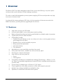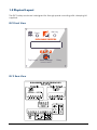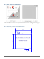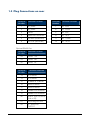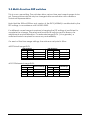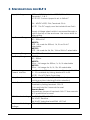
1
ELF2 Earth Leakage Relay
A00842
A00976
A01019
Manual Version 4.1
ELF2 Version 2.2
Operation Manual
ELF2 Manual
Part number:
A00842 500mA 500ms
A00976 Multi-ranging
A01019 Extended-range
110/240VAC, 24 – 48VDC
110/240VAC, 24 – 48VDC
110/240VAC, 24 – 48VDC
Manual Version 4.1
ELF2 Version 2.1
May 2008
Copyrights
All rights reserved. This document may not, in whole or part, be copied, photocopied,
reproduced, translated, or reduced to any electronic medium or machine readable form without
the express written permission of Bramco Electronics.
Disclaimer
Bramco Electronics has made every attempt to ensure that the information contained in this
document is accurate and complete. Bramco Electronics makes no representation or warranties
of merchantability or fitness for any particular purpose. Bramco Electronics reserves the right to
make changes to the system and/or document at any time without notice.
Bramco Electronics
Unit 2&3 Callistemon Close,
Warabrook NSW 2304
Australia
www.bramco.com.au
Ph:
+61 2 4014 4444
Fax: +61 2 4967 4100
Email: [email protected]
ELF2 Manual V4.1
ELF2 Version 2.2
2/17
Contents
1
OVERVIEW
4
1.1
Features
4
1.2
Physical Layout
5
1.3
Plug Connections on rear
7
1.4
Models
8
2
ELF2 OPERATION
9
2.1
Setup
9
2.2
Tripping
10
2.3
Resets
10
2.4
Output & Monitoring
11
2.5
Multi-Function DIP switches
12
3
SPECIFICATIONS FOR ELF 2
13
4
INSTALLATION
14
4.1
Mounting
14
4.2
Cabling
14
4.3
ELF 2 Operating voltage selection
15
4.4
EL Toroids
15
5
FAULT DIAGNOSIS
16
6
ELF 2 TYPICAL CONNECTIONS
17
ELF2 Manual V4.1
ELF2 Version 2.2
3/17
1 OVERVIEW
The Bramco ELF 2 has been designed to detect Earth current faults flowing in a power system
and to provide visual indication of Earth Leakage conditions.
This relay is specifically designed to protect systems supplying VF Drives and provides very high
immunity to converter noise.
It is physically the same package as ELF relay, with the exception of the extra rear socket for
RS485 connection, providing an easy upgrade path for the user.
1.1 Features
•
•
•
•
•
•
•
•
•
•
•
•
•
•
High noise immunity for VSD loads
Accurate and reliable current measurement and trip delays
Easily configured latching/non-latching and failsafe/non-failsafe mode of operation
Toroid open protection and indication
LCD display provides:
o Display of actual leakage current: as a direct mA value, as a bar graph and as a
percentage of the trip point.
o Readout of trip current and delay set points
o Relay operational parameters
o Last fault duration
o Trip indication
Adjustable trip current and delay time from front panel
Front panel reset button, enabled via a link on the rear panel
Provision for a remote reset button
Status LEDs on the front panel for:
o Power
o Warning/fault
Compatible with Bramco’s standard Earth Leakage Toroid range – 500mA, 1A, 2A
etc. (Note: for extended range detection beyond 500mA, matched toroid-relay pairs
must be used)
Current loop or voltage output 4-20mA or 2-10V output
Clear hinged front cover offers protection to IP66 when properly mounted
Multiple input voltage available as standard for relay
Operates on limited and unlimited neutral systems.
ELF2 Manual V4.1
ELF2 Version 2.2
4/17
1.2 Physical Layout
The ELF 2 relay enclosure is designed for through panel mounting with clamping kit
supplied.
O
ELF2 Front View
Warning
BR
A
M
C
Power
EARTH LEAKAGE PROTECTION
ELF 2
Trip Current Show Settings
Delay
Hold for Reset
ELF 2 Rear View
DC
ELF2 Manual V4.1
ELF2 Version 2.2
5/17
ELF 2 Basic Enclosure Dimensions
NOTE: Allow 50 mm minimum rear depth behind ELF 2 to allow for cabling to Pheonix plugs.
ELF 2 Mounting Panel cut-out dimensions
90mm
20mm
10mm
1mm
90mm
ELF2 PANEL CUT OUT
FRONT VIEW
1mm
10mm
20mm
ELF2 Manual V4.1
ELF2 Version 2.2
6/17
1.3 Plug Connections on rear
Terminal
Number
Terminal Function
Terminal
Number
Terminal Function
1
AC power
7
EL N/O
2
AC power
8
EL COM
3
EARTH
9
EL N/C
4
Spare No Connection
10
EL
N/C
5
DC NEG (ISOLATED)
11
EL
COM
6
DC POS (ISOLATED)
12
EL
N/O
Optional RS485 Port
Terminal
Number
Terminal Function
23
RS485
24
RS485 DB
25
RS485 0V
Terminal
Number
DA
Terminal Function
13
EL TOROID
14
EL TOROID
15
SCREEN EL TOROID
16
REMOTE RESET
17
REMOTE RESET
18
ENABLE LOCAL RESET
19
ENABLE LOCAL RESET
20
VOLTS POS OUTPUT
(Link to 22)
21
mA/V Neg OUTPUT
22
4 – 20mA Pos
OUTPUT
ELF2 Manual V4.1
ELF2 Version 2.2
7/17
1.4 Models
Three models of the ELF2 are available:
A00842
Implements the full functionality of the ELF2, with the exception of limiting the trip
parameters to a maximum of 500mA and 500ms. This is in compliance with
AS2081:2002.
A00976
Implements the full feature set described above, and provides the following
options for trip ranges:
• Current ranges – 500mA, 1A, 2A and 5A ranges. Trip point may be set
between 10% and full-scale.
• Time ranges – 500ms, 1s, 2s and 5s ranges. Trip delay time may be set
between 30ms and full-range.
A01019
Implements the full ELF2 feature set, and provides the following options for trip
ranges:
• Current ranges – 2A, 5A, 10A and 20A ranges. Trip point may be set between
10% and full-scale.
• Time ranges – 2s, 5s, 10s and 20s ranges. Trip delay time may be set between
30ms and full-range.
ELF2 Manual V4.1
ELF2 Version 2.2
8/17
2 ELF2 OPERATION
The ELF2 monitors the amount of current passing through an Earth Leakage Toroid.
If the measured current exceeds the trip current for the nominated fault time, the
relay will trip, changing the state of its trip contacts (terminals 7-12) and indicating
a fault on the LCD.
The trip ranges are as follows:
• 50mA to 500mA and 30ms to 500ms for the 500mA/500ms only ELF2 A00842
(AS2081:2002 compliance)
• 10% of full-scale current to full-scale (e.g. 100mA to 1A) and 30ms to fullrange (e.g. 2s) for the multi-range ELF2 A00976 and extended range ELF2
A01019.
PLEASE NOTE: for the multi-range and extended-range ELF2 products, the relay will
be supplied with a matched toroid. It is important that the relay and its matching
Earth Leakage Toroid are used in conjunction with one another, for accuracy and
reliability.
2.1 Setup
The parameters that may be adjusted to set up the ELF2 are the following:
• Trip Delay Time:
Adjusted using the Delay knob on the front panel of the relay.
A cascaded timing scheme (covering all EL protection equipment) is
recommended.
• Trip Current:
Adjusted using the Trip Current knob on the front panel of the ELF2.
• Failsafe/Non-Failsafe:
Set using the selector switch on the rear panel.
In failsafe mode, the trip contacts energise when the relay is healthy – e.g. a
N/C contact will be open when the relay is healthy.
In non-failsafe mode, the trip contacts energise when the relay is unhealthy
– e.g. a N/C contact will be closed when the relay is healthy.
• Latching/Non-Latching:
Set using the selector switch on the rear panel.
In the latching mode, the trip contacts remain in the tripped position until
the fault clears AND a reset (either local or remote) is initiated by the user.
ELF2 Manual V4.1
ELF2 Version 2.2
9/17
2.2 Tripping
The conditions for a trip are:
• EL current exceeding the trip current passes through the detection toroid for
a period greater than the delay time specified.
• The toroid is disconnected from the relay.
If a trip condition is detected, the trip contacts change state. In failsafe mode, the
contacts will de-energise under a trip condition. In non-failsafe, the contacts
energise with a trip.
Note: the commit time for a trip is 25ms less than the delay time. That is, if a fault
condition persists for longer than 25ms less than the trip delay, but shorter than the
trip delay itself, the unit will still trip. This is a deliberate behaviour, to adjust for the
internal hardware pickup time for handling the trip.
2.3 Resets
To reset the ELF2, the fault (earth leakage or no toroid) must firstly be cleared. If the
trip condition was an EL fault, the measured earth leakage current must fall below
80% of the trip current set point.
In non-latching mode, the ELF2 will reset automatically once the fault is gone. In
latching mode, the user must reset the ELF2 manually by either using a local or
remote reset.
Local Reset must be enabled by linking terminals 18 and 19. The reset button must
be pushed, held for 2 seconds and released to reset the unit.
Remote Reset can be enabled by wiring a N/O pushbutton to terminals 16 and 17.
The button must change state from open to closed to carry out the reset.
ELF2 Manual V4.1
ELF2 Version 2.2
10/17
2.4 Output & Monitoring
There are 3 output types:
• LED indication
A steady green LED indicates that the unit is powered.
A flashing red LED indicates that the EL fault level is between 80% and 100%
of the trip point
A steady red LED indicates EL fault level > 100% trip point or toroid fault
• 4-20mA / 2-10V terminals
A scaled indication of the percentage of full scale: 4mA/2V indicates no EL
fault current, 20mA/10V indicates EL fault level ≥ full scale.
4-20mA: Terminal 21 positive, terminal 22 negative. Maximum loading 250Ω.
2-10V: Terminals 20 & 22 linked. Terminal 21 negative, terminal 22 positive.
Note: the output is scaled against the full scale of the unit (500mA, 1A etc)
rather than the set point.
• LCD
Four main functions:
o Main Screen: shows trip settings and fault level
o Settings Screen: shows trip settings (time, current), plus operational
mode (failsafe/non, latching/non). Accessed via button press.
o Fault Indication: shows fault type when relay is tripped or latched
o Fault Duration: shows last EL fault duration. Accessed by holding
button.
ELF2 Manual V4.1
ELF2 Version 2.2
11/17
2.5 Multi-Function DIP switches
This is a non user setting. The switches allow various time and current ranges to be
set. These switches should only be changed after consultation with a Bramco
Technical Representative.
Note that the 500mA/500ms-only version of the ELF2 (A00842) is unaffected by the
DIP settings, in accordance with AS2081:2002.
If a different current range is required, changing the DIP settings is insufficient to
complete the change. The relay and toroid must both be sent to Bramco for
adjustments and recalibration. For extended range ELF2s (1A or greater), a
matched toroid is required for accuracy and reliability.
On each of the time range settings, the minimum set point is 30ms.
A00976 Multi-range ELF2:
DIP Numbers
1
2
OFF
OFF
OFF
ON
ON
OFF
ON
ON
Current Range
500mA
1A
2A
5A
DIP Numbers
3
4
OFF
OFF
OFF
ON
ON
OFF
ON
ON
Time Range
500ms
1s
2s
5s
A01019 Extended-range ELF2:
DIP Numbers
1
2
OFF
OFF
OFF
ON
ON
OFF
ON
ON
ELF2 Manual V4.1
Current Range
2A
5A
10A
20A
DIP Numbers
3
4
OFF
OFF
OFF
ON
ON
OFF
ON
ON
ELF2 Version 2.2
Time Range
2s
5s
10s
20s
12/17
3 SPECIFICATIONS FOR ELF 2
Supply Voltage
120V or 240V Selectable ±20% 50/60Hz, 2VA,
Terminals 1, 2 & 3.
NOTE: ELF 2 when shipped is set to 240vAC
24 – 48VDC ±20%, 2VA, Terminals 5 & 6.
NOTE: This DC supply must be isolated from Earth
Supply Voltage select switch is accessed through a
hole in the top of the enclosure. Use screw driver to
alter setting.
Trip Current Range
A00842:
50 – 500mA AC
A00976:
10% - full-scale for 500mA, 1A, 2A or 5A AC
selectable.
A01019:
10% - full-scale for 2A, 5A, 10A or 20A AC selectable.
Frequency Range
20 – 200Hz Sinusoidal
Trip Delay Range
A00842:
30 – 500ms
A00976:
30ms – full-range for 500ms, 1s, 2s, 5s selectable
A01019:
30ms – full-range for 2s, 5s, 10s, 20s selectable
Earth Leakage
Current Monitor
4 – 20mA into 250 ohms maximum. Terminals 21 & 22
2 – 10v available by linking terminal 22 to 20.
NOTE: Do NOT Earth Pos or Neg.
Relay Function
Failsafe or Non-Failsafe (Switch selection)
Latching or Non-Latching (Switch selection)
Latch Reset
Local Reset:
Enabled by linking terminals 18 & 19
Push and hold for 2 seconds for reset
Remote Reset:
Momentary closure of terminals 16 & 17 from remote
N/O pushbutton for reset
ELF 2 Contact ratings
2 x C/O 5A 250vAC, 100vA max
5A 30vDC Resistive
3A 30vDC Inductive load 90W L/R 7mS
Maximum Switching
Voltage
380vAC/125vDC
ELF2 Manual V4.1
ELF2 Version 2.2
13/17
4 INSTALLATION
4.1 Mounting
The ELF 2 relay is fascia packaged for through-panel mounting. Panel cut out is 90
x 90 mm. See the “Physical Layout” section for cut-out detail.
Use sealing gasket provided, positioned behind front bezel for panel sealing, and
use the 2 adjustable clamps to fasten ELF 2 to mounting panel. When mounted as
above the exposed ELF 2 Relay bezel has IP66 rating.
ELF 2 relay and EL Toroid should be mounted away from stray flux sources such as
power supplies, transformers, control relays and contactors and cables carrying
load currents.
4.2 Cabling
Use 2 core screened cable for the following inputs:
• EL Toroid
• EL Remote LATCH RESET (voltage free contact).
Each individual cable screen should be connected to the ELF 2 relay to Terminal
15.
NOTE: Do not earth the non-relay end of these screened cables.
It is recommended that these 2 screened cables are run by a direct route to the
ELF 2 relay, BUT are not to run with, or in cable harness or ducting with control or
power cabling.
Where necessary, cross other cables at 90 degrees and provide maximum
clearance from high voltage/current circuits as much as practically possible.
ELF2 Manual V4.1
ELF2 Version 2.2
14/17
4.3 ELF 2 Operating voltage selection
Two options are available for powering the ELF2 – AC or LV DC
AC Power:
Either 120vAC or 240vAC input is connected to Terminals 1 and 2.
Before powering the ELF 2, check and adjust to the matching voltage setting on
the internal voltage selector switch. The switch is accessed through the top of the
relay ELF 2 body.
The factory setting is 240v.
NOTE: If powered from 240vAC with the 120v switch setting, the ELF2 will be
damaged.
Low voltage DC Power:
For 24 – 48VDC, input is connected to terminals 5 (Neg) and 6 (Pos). This must be
an isolated power supply source.
NOTE: For correct operation of the ELF2, this supply must not be earthed.
4.4 EL Toroids
IMPORTANT: Match the EL Toroid Scaling with ELF 2 relay.
For the A00842, a standard 500mA Bramco EL toroid should be used.
For the A00976 and A01019, a current-matched and calibrated toroid pair should
be used.
EL toroids have a powder coated mild steel, open faced enclosure, which acts as
a shield to stray flux. For this to be effective the open side of the ELT should face
away from stray flux sources such as transformers, relays and contactors, and for
best effect, facing but not touching the steel enclosure body.
The three phase load power cables should be arranged to pass symmetrically
through the centre of the EL toroid window. If the cables are asymmetrical through
the centre of the toroid, incorrect EL detection may occur.
ELF2 Manual V4.1
ELF2 Version 2.2
15/17
5 FAULT DIAGNOSIS
To assist in fault diagnosis, a variety of typical faults are shown, with possible
solutions given
Indication
Power LED is OFF
Power LED is ON
Warning LED is OFF
Warning LED FLASHING
Warning LED SOLID
CCCmA EEEEEEEEEE
AAAmA DD% BBBmA
LATCHING
AAAmA
FS
BBBmA
FAULT DURATION:
AAAms
LOCAL RESET
DISABLED
HOLD BUTTON
TO RESET
RELEASE BUTTON
TO RESET
EL FAULT
TRIPPED LATCHED
TOROID FAULT
TRIPPED LATCHED
EL FAULT
TRIPPED NO LATCH
TOROID FAULT
TRIPPED NO LATCH
RELAY TRIPPED
TRIPPED LATCHED
ELF2 Manual V4.1
Possible Condition/Suggestion
LED Indication
Power supply is incorrectly connected or switched off. Check either 110/240VAC
or 24-48VAC/DC is connected.
Relay is operational. Control relay output state is dependent on failsafe/nonfailsafe and the presence of any fault conditions
Earth leakage current below 80% AND toroid connected properly
Earth leakage current above 80% but beneath 100% of trip point
Earth leakage current above 100% OR toroid fault
LCD - Information Screens
Status Screen
A: Fault current set point, mA or A
B: Trip delay set point, ms or s
C: Measured earth leakage current, mA or A
D: Measured earth leakage as a percentage of set point
E: Bar graph representation of percentage earth leakage
Constantly viewable if no button pressed or fault condition present
Summary Screen
A: Fault current set point, mA or A
B: Trip delay set point, ms or s
Shows operational mode: latching/non-latching, failsafe/non-failsafe
Accessed by momentary press of local reset. Remains for 5 seconds.
Fault Duration Screen
A: Time in ms or s of last fault detected by ELF2
Accessed by pressing local reset for 2 seconds. Remains for 5 seconds.
Local Reset Lockout Screen
Local reset is not enabled; link terminals 18 & 19 to enable.
Local Reset Screens
Viewable by initiating a local reset when a latched fault has occurred and the
fault condition has cleared
LCD - Fault Messages
Earth leakage current has exceeded trip current and time settings. Latch has
been set. Fault must clear and manual latch reset to become healthy.
Open toroid - check toroid connections. Fault must clear and manual latch reset
for relay to become healthy.
Earth leakage current has exceeded trip current and time settings. Relay will
become healthy when fault clears.
Open toroid - check toroid connections. Relay will become healthy when fault
clears.
Latch from a previous fault exists, fault type unable to be determined. Usually
when latched at startup. Requires latch reset for healthy relay.
ELF2 Version 2.2
16/17
6 ELF 2 TYPICAL CONNECTIONS
AC LOAD
L1
L2
L3
REAR VIEW A00842
ELF 2 RELAY
MC1
MC1
MC1
CONTACTOR
1
2
3
4
A
N
E
5
6
7
8
N/C
-+
24 - 48VAC/DC
DC
23
24
DA
DB
9
10
11
12
MAX RATING
5A 240VAC
25
RS485 PORT
COM
OPTIONAL
NFS NO LATCH
22
21
20
19
18
17
16
15
14
13
MODE SELECT
SWITCHES
FS
SCREEN
ELT
ELT
BRAMCO
EL TOROID
LINK TO ENABLE
LOCAL RESET
LATCH
LINK FOR 2-10V
2 CORE SCREENED CABLE
ALTERNATIVE ARANGEMENT
BACK-UP PROTECTION
ELT
2 CORE SCREENED CABLE
CORE BALANCE PROTECTION
PB1
REMOTE RESET
2 CORE SCREENED CABLE
NEG POS
4 - 20mA OUTPUT
OR
2 - 10V OUTPUT
NGR
TRANSFORMER SUPPLY
ELF2 Manual V4.1
ELF2 Version 2.2
17/17