1
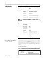
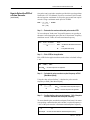
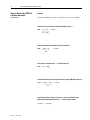
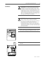
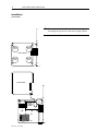
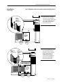
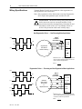
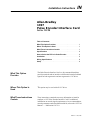
Installation Instructions
IN
Allen-Bradley
1397
Pulse Encoder Interface Card
Cat. No. 1397-PE
Table of Contents
What This Option Provides . . . . . . . . . . . . . . . . . . . . . . . . 1
Where This Option Is Used . . . . . . . . . . . . . . . . . . . . . . . . 1
What These Instructions Contain
. . . . . . . . . . . . . . . . . . . 1
Specifications . . . . . . . . . . . . . . . . . . . . . . . . . . . . . . . . . 2
How to Select the PPR of a Pulse Encoder
. . . . . . . . . . . . 2
Installation . . . . . . . . . . . . . . . . . . . . . . . . . . . . . . . . . . . . 5
Wiring Specifications . . . . . . . . . . . . . . . . . . . . . . . . . . . . 8
Setup . . . . . . . . . . . . . . . . . . . . . . . . . . . . . . . . . . . . . . . . 9
What This Option
Provides
The Pulse Encoder Interface Card is a drive mounted board that
provides terminals and an interface to differential encoder feedback
signals for both regenerative and non-regenerative 1397 drives.
Where This Option Is
Used
This option may be used with all 1397 drives.
What These Instructions
Contain
These instructions contain the necessary information to install &
configure a 1397 Pulse Encoder Interface Card. For additional
information on encoder signal requirements, wire recommendations,
encoder parameters and related function blocks, refer to the 1397 User
Manual — Publication 1397-5.0.
1397-5.13
June, 1997
2
1397 Pulse Encoder Interface Card
Specifications
How to Select the PPR of
a Pulse Encoder
Pulse Encoder
Requirements
Waveform:
Square Wave — Constant Amplitude
Over Entire Speed Range, Including Zero
Speed
Differential
Output:
Single-Channel or Quadrature
(Dual-Channel)
Duty Cycle:
50% Nominal
Quadrature:
Required for All Regenerative Drives
Line Drivers:
May Be Required to Satisfy the Pulse
Encoder Interface Card’s Voltage Limits
Wiring
Requirements
Refer to the 1397 User Manual — Publication 1397-5.0
Pulse Encoder
Interface Card
Requirements
Power Supply:
+15VDC, ±5%, 200mA Maximum
Absolute:
Max Frequency
100kHz
Min Frequency:
0kHz
Recommended:
Max Frequency
73kHz
Differential
Input
Requirements
Voltage:
+25VDC Maximum to Common
+5VDC Minimum Differential
+15VDC Maximum Differential
Input Impedance:
11kΩ
Line Termination:
100Ω in Series with (1) 3900pf Capacitor
A 120 PPR pulse encoder can maintain a minimum speed of 25 RPM
at the accuracy listed in the Specifications above. The drive can operate
below minimum motor speed but with degraded accuracy. If a lower
motor speed is required, a pulse encoder with a higher PPR rating is
required.
To select a pulse encoder —
Step 1 — Determine the pulse encoder’s minimum PPR requirement.
PPR 1 = [1] × [60]
——————
N 1 × 0.02
where:
PPR 1 = The Pulse Encoder’s Minimum
Pulses-per-Revolution
N1
1397-5.13
June, 1997
= The Required Minimum Motor Speed in RPM
1397 Pulse Encoder Interface Card
How to Select the PPR of
a Pulse Encoder
(continued)
3
One pulse/scan is required to meet the specified drive speed regulation
listed in the 1397 User Manual. For a drive scan time of 0.02 seconds,
the card requires a minimum of (50) pulses-per-second from a pulse
encoder. Using a minimum motor speed of 25 RPM:
PPR 1 = [1] × [60] = 120 PPR
——————
25 × [0.02]
Step 2 — Determine the maximum allowable pulse encoder PPR.
To leave adequate "head room" for possible motor over speeding at
the motor’s rated nameplate speed, the card’s "head room" frequency
should not exceed 73kHz, the card’s maximum frequency.
PPR 2 = 73,000 × 60 Sec/Min
———————————
N2
where:
PPR2 = The Maximum Allowable Pulse Encoder
PPR
N2
= P.041 [Max Motor Speed]
Step 3 — Pick a PPR for the application.
Pick a PPR for the application between the values calculated in Steps
1 & 2.
PPR 1 ≤ PPR req ≤ PPR 2
where PPR req = The PPR Required for the Application
Step 4 — Calculate the pulse encoder’s required frequency at P.041
[Max Motor Speed].
Using the value selected in Step 3, calculate the pulse encoder
frequency at P.041 [Max Motor Speed].
Freq req = N2 × PPR req
———————
60
where:
Freq req = The Pulse Encoder’s Required Frequency
PPR req = The PPR Required for the Application
Step 5 — Confirm that the pulse encoder frequency ≤ 80% of the pulse
encoder’s maximum rated nameplate frequency.
To ensure that the pulse encoder has adequate "head room" for motor
overspeeding, confirm that the pulse encoder’s required frequency is
≤ 80% of the pulse encoder’s maximum rated nameplate frequency.
Freq req ≤ 80% × Freq PE
where Freq PE = The Pulse Encoder’s Maximum Rated Nameplate Frequency.
1397-5.13
June, 1997
4
1397 Pulse Encoder Interface Card
How to Select the PPR of
a Pulse Encoder
Example
(continued)
Using a 5,000 RPM motor with a requirement to run as low as 25 RPM —
Determine the Pulse Encoder’s Minimum PPR Requirement —
PPR 1 = [1] × [60] = 120 PPR
———————
25 × [0.02]
Determine the Maximum Allowable Pulse Encoder PPR —
PPR 2 ≤ 73,000 × 60
———————
5000
≤
876 PPR
Pick a PPR for the Application — In This Example 500
PPR 1 ≤ 500 ≤ PPR 2
Calculate the Pulse Encoder’s Required Frequency at P.041 [Max Motor Speed] —
Freq req = [5,000] × [500] = 41.67kHz
————————
60
Confirm That the Pulse Encoder Frequency ≤ 80% of the Pulse Encoder’s
Maximum Rated Nameplate Frequency — In This Example 120kHz
41.678k Hz ≤ .8 (120,000)
1397-5.13
June, 1997
1397 Pulse Encoder Interface Card
Installation
!
!
5
ATTENTION: This board contains ESD (Electrostatic
Discharge) sensitive parts and assemblies. Static control
precautions are required when installing, testing, servicing
or repairing this assembly. Component damage may result
if ESD control precautions are not followed. If you are not
familiar with static control procedures, reference publication
8000-4.5.2, "Guarding Against Electrostatic Damage" or any
other applicable ESD protection handbook.
ATTENTION: Electric Shock can cause injury or death.
Remove all power before working on this product.
The drive is at line voltage when connected to incoming AC
power. Before proceeding with any installation or
troubleshooting activity, disconnect, lockout and tag all
incoming power to the drive. Verify with a voltmeter than no
voltage exists at terminals L1, L2 and L3 on the drive input
power terminal block.
❐ 1 Remove and lock-out all incoming power to the drive. Loosen
the (2) captive retaining screws and remove the drive cover.
Captive
Thumb
Screw
Captive
Thumb
Screw
Captive
Carrier
Screw
❐ 2 Loosen the captive carrier retaining screw and swing the carrier
door open.
J28
1397-5.13
June, 1997
6
1397 Pulse Encoder Interface Card
Installation
(continued)
❐ 3 To remove the carrier shield, remove the (4) retaining screws
and unplug the ground wire at the Power Supply Board.
Retaining
Screw
Retaining
Screw
Carrier Shield
Retaining
Screw
Retaining
Screw
Carrier Shield
Connector
J17
Power
Supply
Board
1397-5.13
June, 1997
J17
1397 Pulse Encoder Interface Card
Installation
7
If an I/O Expansion Card is also required, complete both Steps 4 and 5.
(continued)
❐ 4 Install the Pulse Encoder
Interface Card in the drive
carrier using the (2) pan head
screws provided, then plug
the middle ribbon cable
connector into J1.
Pulse
Encoder
Interface
Card
Connector J1
J17
J1
Pulse
Encoder
Interface
Card
+15V COM A ANOT B BNOT
J6 71 72 73 74 75 76 J5
71 72 73 74 75 76
+15V COM A ANOT B BNOT
Pan
Head
Screw
I/O
Expansion
Card
Connector J2
Pan
Head
Screw
Pulse
Encoder
Interface
Card
Connector J1
J17
❐ 5 If an I/O Expansion Card is
used, the Pulse Encoder
Interface Card is mounted
piggy back on the I/O
Expansion Board and
connected using hardware
included with the Pulse
Encoder Interface Kit.
68 69
68 69
PULSE ENCODER RIBBON CABLE
J10
I/O EXPANSION CARD
J1
J1
J2
Pulse
Encoder
Interface
Card
INT EXT
J15
IOUT
SOURCE
+15V COM A ANOT B BNOT
MA
V
J14
J6 71 72 73 74 75 76 J5
J11
J12
71 72 73 74 75 76
+15V COM A ANOT B BNOT
ANALOG
OUTPUT 1
PARK
V MA VOLTS
J5 (ANALOG
J7
J6
INPUT) 14-20
J8
J9
38 39 40 41 42 43 44 50 51 52 53 54 55 56 57 58 59 60 61 62 63 64 65 66 67 68 69
Pan
Head
Screw
Pan
Head
Screw
38 39 40 41 42 43 44 50 51 52 53 54 55 56 57 58 59 60 61 62 63 64 65 66 67 68 69
1397-5.13
June, 1997
8
1397 Pulse Encoder Interface Card
Wiring Specifications
Terminal Blocks J5 and J6 are available for either regenerative or
non-regenerative drive connection.
Note: Only regenerative drives allow motor reversing. Regenerative
drives require that quadrature pulse encoders be used.
!
ATTENTION: The incorrect wiring of the pulse encoder
and/or motor can cause an overspeed condition. Verify
correct motor and pulse encoder polarity in the Start-Up and
Adjustment section of the 1397 User Manual. Failure to
observe this precaution could result in bodily injury.
Non-Regenerative Drives — Non-Reversing Motor Applications
Shield 1
to Chassis
Ground Stud
(High)
(Low)
A
(High)
A
71 +15V
72 COM
Single Channel
Pulse Encoder
— No Motor Reversing —
(Low)
Period 2
TB J6
73 A
74 A
75 B
76 B
TB J5
1 Belden 9728 or 9730 — (2) Conductor Twisted Shielded Cable
Refer to the Cable and Wire Recommendations in the 1397 Use
Manual for additional Wiring Specifications
2 Period =
1
frequency
Regenerative Drives — Reversing and Non-Regenerative Motor Applications
(High)
(Low)
A
(High)
A
(Low)
B
(High)
Shield 1
to Chassis
Ground Stud
71 +15V
72 COM
Quadrature
(Dual-Channel)
Pulse Encoder
for
Regenerative Drives
73 A
74 A
75 B
(Low)
76 B
(High)
TB J5
(Low)
Period 2
B
1 Belden 9728 or 9730 — (2) conductor twisted shielded cable.
Refer to the Cable and Wire Recommendations in the 1397
User Manual for additional wiring specifications.
2 Period =
1397-5.13
TB J6
June, 1997
1
frequency
1397 Pulse Encoder Interface Card
Setup
9
To configure the board for the selected pulse encoder, (4) parameters
are set. An additional parameter may be checked for board status.
!
ATTENTION: The incorrect setting of parameters P.039 or
P.048 can cause an overspeed condition. Both parameters
must be set by a qualified person who understands the
significance of setting them. Set the value of these parameters
accurately per your application requirements. Failure to
observe this precaution could result in bodily injury.
P.039 — Set Feedback Type to Encoder
This parameter is set to match the type of drive feedback signal used.
Default Value = Arm Volt
P.041 — Set Max Motor Speed
This parameter is set to match the motor’s rated nameplate speed (N2),
the same value that was used in Step 2 on page 3.
Default Value = 500 RPM
P.048 — Set Encoder PPR
This parameter is set to the pulse encoder’s rated PPR (PPR req), the
value that was selected in Step 3 on page 3.
Default Value = 18 PPR
P.049 — Set Encoder Quad to Off (Disabled) for a Single-Channel Encoder
Set Encoder Quad to On (Enabled) for a Quadrature
(Dual-Channel) Encoder
This parameter is set to match the type of pulse encoder, either
single-channel or quadrature (dual-channel).
Default Value = On
1397-5.13
June, 1997
10
1397 Pulse Encoder Interface Card
Notes
________________________________________________________________________________________
________________________________________________________________________________________
________________________________________________________________________________________
________________________________________________________________________________________
________________________________________________________________________________________
________________________________________________________________________________________
________________________________________________________________________________________
________________________________________________________________________________________
________________________________________________________________________________________
________________________________________________________________________________________
________________________________________________________________________________________
________________________________________________________________________________________
________________________________________________________________________________________
________________________________________________________________________________________
________________________________________________________________________________________
________________________________________________________________________________________
________________________________________________________________________________________
________________________________________________________________________________________
________________________________________________________________________________________
________________________________________________________________________________________
________________________________________________________________________________________
1397-5.13
June, 1997
1397 Pulse Encoder Interface Card
11
Notes
________________________________________________________________________________________
________________________________________________________________________________________
________________________________________________________________________________________
________________________________________________________________________________________
________________________________________________________________________________________
________________________________________________________________________________________
________________________________________________________________________________________
________________________________________________________________________________________
________________________________________________________________________________________
________________________________________________________________________________________
________________________________________________________________________________________
________________________________________________________________________________________
________________________________________________________________________________________
________________________________________________________________________________________
________________________________________________________________________________________
________________________________________________________________________________________
________________________________________________________________________________________
________________________________________________________________________________________
________________________________________________________________________________________
________________________________________________________________________________________
________________________________________________________________________________________
1397-5.13
June, 1997
Rockwell Automation helps its customers receive a superior return on their investment by bringing
together leading brands in industrial automation, creating a broad spectrum of easy-to-integrate
products. These are supported by local technical resources available worldwide, a global network
of system solutions providers, and the advanced technology resources of Rockwell.
Worldwide representation.
Argentina • Australia • Austria • Bahrain • Belgium • Bolivia • Brazil • Bulgaria • Canada • Chile • China, People’s Republic of • Colombia • Costa Rica • Croatia • Cyprus
Czech Republic • Denmark • Dominican Republic • Ecuador • Egypt • El Salvador • Finland • France • Germany • Ghana • Greece • Guatemala • Honduras • Hong Kong
Hungary • Iceland • India • Indonesia • Iran • Ireland • Israel • Italy • Jamaica • Japan • Jordan • Korea • Kuwait • Lebanon • Macau • Malaysia • Malta • Mexico
Morocco • The Netherlands • New Zealand • Nigeria • Norway • Oman • Pakistan • Panama • Peru • Philippines • Poland • Portugal • Puerto Rico • Qatar • Romania • Russia
Saudi Arabia • Singapore • Slovakia • Slovenia • South Africa, Republic of • Spain • Sweden • Switzerland • Taiwan • Thailand • Trinidad • Tunisia • Turkey • United Arab Emirates
United Kingdom • United States • Uruguay • Venezuela
Rockwell Automation Headquarters, 1201 South Second Street, Milwaukee, WI 53204-2496 USA, Tel: (1) 414 382-2000, Fax: (1) 414 382-4444
Publication 1397-5.13 — June, 1997
P/N 184653
Copyright 1997 Rockwell International Corporation
Printed in USA