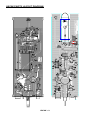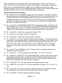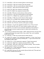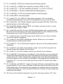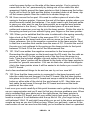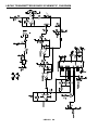
1
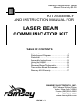
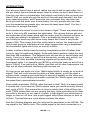
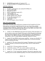
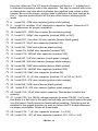
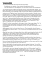
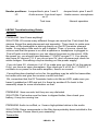
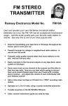
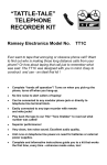
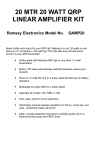
LASER BEAM COMMUNICATOR Ramsey Electronics Model No. LBC6K Have you ever wanted to communicate in a new and interesting way? Forget stringing wires and tin cans between your house and your neighbor’s! Now you can send messages on a beam of light! Pretend you’re on one of those space adventure shows we’ve all watched on TV. Laser beam communication for the new millenium! • Uses a standard pen-laser diode to transmit voice and sound over several hundred feet through the air, and several miles with good optical fiber. • Uses a pulse-width modulator running at 20kHz for good audio reproduction. • Built-in AGC for sensitivity to low level sounds and good transmission of high level sounds without distortion. • Pen laser included! Use even better laser modules for farther transmission. • A lot of fun to transmit to your friend’s house through the window! • Powered by any 9 - 12 VDC source. • Complete and informative instructions guide you to a kit that works the first time, every time. LBC6K • 1 PARTIAL LIST OF AVAILABLE KITS: RAMSEY TRANSMITTER KITS • FM10A, FM25B FM Stereo Transmitters • FM100 Super Pro FM Transmitter • AM1, AM25 Transmitter RAMSEY RECEIVER KITS • FR1 FM Broadcast Receiver • AR1 Aircraft Band Receiver • SR2 Shortwave Receiver • AA7 Active Antenna • SC1 Shortwave Converter RAMSEY HOBBY KITS • SG7 Personal Speed Radar • SS70A Speech Scrambler/Descrambler • TT1 Telephone Recorder •TG2 DTMF Tone Grabber • SP1 Speakerphone • MD3 Microwave Motion Detector • PH14 Peak hold Meter • LC1 Inductance-Capacitance Meter RAMSEY AMATEUR RADIO KITS • HR Series HF All Mode Receivers • QRP Series HF CW Transmitters • CW7 CW Keyer • PA Series VHF and UHF Power Amplifiers • QRP Power Amplifiers RAMSEY MINI-KITS Many other kits are available for hobby, school, scouts and just plain FUN. New kits are always under development. Write or call for our free Ramsey catalog. LBC6K LIGHT BEAM COMMUNICATOR INSTRUCTION MANUAL Ramsey Electronics publication No. MLBC6K Rev. 1.2 December 2002 COPYRIGHT 2002 by Ramsey Electronics, Inc. 590 Fishers Station Drive, Victor, New York 14564. All rights reserved. No portion of this publication may be copied or duplicated without the written permission of Ramsey Electronics, Inc. Printed in the United States of America. LBC6K • 2 Ramsey Publication No. LBC6K Manual Price Only $5.00 KIT ASSEMBLY AND INSTRUCTION MANUAL FOR LASER BEAM COMMUNICATOR KIT TABLE OF CONTENTS Introduction .............................................4 Parts Layout Diagram .............................9 Parts List...............................................10 Assembly Instructions...........................12 Using the LB6K.....................................18 Troubleshooting ....................................20 Receiver Board Schematic ...................23 Transmitter Board Schematic ...............24 Ramsey Kit Warranty............................27 RAMSEY ELECTRONICS, INC. 590 Fishers Station Drive Victor, New York 14564 Phone (585) 924-4560 Fax (585) 924-4555 www.ramseykits.com LBC6K • 3 INTRODUCTION You and your friend have a pair of radios you use to talk to each other, but did you notice that sometimes people listen in when you don’t want them to? How can you have a conversation that nobody can listen to but you and your friend? Well you could encrypt the audio of the radio and decode it, but that is an expensive option, and if someone has a decoder they can listen too. But if we send the audio over a laser beam, the only people who can hear your conversation are people who can see the laser beam itself. You don’t even have to encrypt the audio! Ever wonder how sound is sent over a beam of light? There are several ways to do it. One is to AM modulate the light beam. This means that we will vary the brightness of the beam along with the audio, and the detector will give us an output according to brightness. This is probably the simplest way, but can’t really be done very well since many lasers don’t have a very broad range of AM. This means that if the audio level is too low, the laser turns off! This is also prone to interference from other sources that vary in brightness like fluorescent lights which turn on and off at 60Hz. A laser module is better used for turning completely on and off rather than trying to vary its brightness slightly. Solid-state lasers perform better this way than with AM modulation. The detector then will see the on and off state very easily. If we turn a laser on and off at a known rate, usually very quickly, we can ignore all other possible interfering signals on the receiver like fluorescent lights. For example our LBC6K is turning the laser on and off at a rate of 18kHz. If we just look at 18kHz, and filter out all other frequencies, we filter out all other potential interfering light sources too. So how do we get audio out of an 18kHz signal which is simply an on and off signal? Well we could encode the data in a data stream, much like what a modem does, meaning we would have to decode it digitally on the other end. Otherwise we could simply pulse width modulate the 18kHz signal, and use a low-pass filter to demodulate the audio. Pulse width modulation (PWM); what the heck is that? Well, it is exactly what it sounds like. If you have an 18kHz square wave you would normally have a duty cycle of 50%. This means the on time is exactly that of the off time per cycle. PWM means that you are varying this duty cycle according to the data you wish to transmit; in our case it is audio. A high signal level would have a longer on time vs. off time, and a quiet signal would have shorter on time vs. off time. The total time per cycle always remains the same. See the following diagram and you will see the waveforms in the LBC6K. The top signal is the 18kHz clock. The middle signal is the clock converted to a LBC6K • 4 PWM signal which has an encoded signal in it. The bottom signal is the decoded PWM of the middle PWM signal. Note how when there is a lot of on time (high) on the PWM signal, the resulting decoded signal is higher, and when there is a lot of off time (low) the signal is lower. The receiver module of your LBC6K is pretty simple. It consists of a very sharp low-pass filter at 6kHz and an audio amplifier. The filter is sharp to reject the 18kHz PWM clock, but let the audio encoded from 6kHz on down through. 6kHz and below is perfect for transmitting voice signals. Below you can see the various stages of filtering in the receiver. The top trace is the unfiltered received PWM signal right at the collector of Q1 (the signal is small, but this is what it looks like). The middle trace is after the first stage of filtering, which is close to what you would see on pin 14 of U1. Notice how even through it has the 18kHz signal on it, it more closely resembles the final filtered output of the bottom trace, which is seen at pin 7 of U1. The receiver is a bit more complex and many of the more complex parts are contained in the microcontroller. The microcontroller (U3) performs the AGC LBC6K • 5 for you, and also digitizes the incoming audio from the microphone with an internal analog to digital converter and converts it to our 18kHz PWM signal. Before we convert the audio from the microphone however, we have to first boost the microphone’s small output of only a few milivolts up to a usable level of a few volts. This is done with U1A, a high gain stage. This stage has a gain of 100, so a small signal of only 100uV will be amplified to a signal of 10mV. The next two stages are low pass filtering. If you compare this filter with the one on the receiver you will see that they are the same. It is a 6kHz sharp low-pass filter. Why do we low-pass filter the audio before digitizing it? It is to prevent signals more than 1/2 of the sampling rate from being digitized and then transposed when they are received. While this may be what you want for a voice scrambler, it is not what we want for transmitting audio. This magical 1/2 of the sampling rate is called the Nyquist frequency. Any incoming frequency above this 1/2 point is not decoded as expected. For example, if a 10kHz signal came in and was digitized at a rate of 18kHz, we would actually get a 1kHz signal at the output of the receiver instead of the intended 10kHz. You can figure this out by realizing that with a Nyquist frequency of 9kHz (our sampling rate is 18kHz), anything over the Nyquist will be seen as the (incoming frequency - Nyquist frequency). So 10kHz - 9kHz = 1kHz. So this may be more information than you really wanted to read, but the Nyquist frequency is very important in many aspects of digital sound. When you are playing MP3s on your computer, they are usually listed as having a certain sampling rate, usually 128kHz. This means that the best frequency response of the audio clip is 64kHz, which is pretty good. The practical reproduction is actually more like 80% of the Nyquist. You may find some audio files which are sampled at 32kHz, which means the highest they can reproduce is 16kHz, this means that the 80% mark is 12kHz, which for decent music reproduction is pretty poor. Since we are only reproducing voice we can stay down at a sampling rate of 18kHz, so the highest we can reproduce is 9kHz, and we filter down to 6kHz to hit that 80% mark for decent voice audio. Ok, so now we have filtered audio ready to sample. The microcontroller samples the filtered audio at a rate of 18kHz, but how is it performing the automatic gain control (AGC)? It does this by looking at the largest values of the incoming samples, and turning pins 11, 12, and 13 into high impedance (off) or low impedance (on) to vary the gain of U1:B, which is set up to be a non-inverting opamp with variable gain. The gain is found by the simple formula of Av = 1 + Rf/Ri. Rf is R20, which is a 100k reistor, and Ri can be any combination of R17, 18, 19, and 24. With all three pins on, R18, 19, 24, LBC6K • 6 and 17 are all in parallel, making U1:B have a gain of (Av = 1+ 5.6k/100k) or 17.6. When all three pins are off, only R17 is in circuit making the gain (Av = 1 + 100K/100K) or 2. This gives a decent range of amplification for small to large signals, and is controlled by the microcontroller. The AGC of the microcontroller tries to keep the signal within the range of the analog to digital converter so that we have the best possible data reproduction, so the gain is always changing on the last stage to keep it there. Once the sample is taken in the microcontroller, it is tested for level and the AGC may or may not be adjusted. It is then converted to a PWM pulse and sent to pin 9, where Q1 is used to turn the laser module on and off for the single sample/cycle. Now the laser beam is sent to the receiver where it is detected and converted back to an audio signal where you can listen to it on a speaker or earphones! We know this may be a bit confusing, but there are a lot of principles of digital data and reproduction packed into this one small kit. If you are interested in learning more, there are a lot of resources on the internet and in your local library. RAMSEY Learn-As-You-Build KIT ASSEMBLY There are numerous solder connections on the LBC6K printed circuit board. Therefore, PLEASE take us seriously when we say that good soldering is essential to the proper operation of your transmitter! • • • • Use a 25-watt soldering pencil with a clean, sharp tip. Use only rosin-core solder intended for electronics use. Use bright lighting, a magnifying lamp or bench-style magnifier may be helpful. Do your work in stages, taking breaks to check your work. Carefully brush away wire cuttings so they don't lodge between solder connections. We have a two-fold "strategy" for the order of the following kit assembly steps. First, we install parts in physical relationship to each other, so there's minimal chance of inserting wires into wrong holes. Second, whenever possible, we install in an order that fits our "Learn-As-You Build" Kit building philosophy. This entails describing the circuit that you are building instead of just blindly installing components. We hope that this will not only make assembly of our kits easier, but help you to understand the circuit you’re constructing. LBC6K • 7 For each part, our word "Install" always means these steps: 1. Pick the correct part value to start with. 2. Insert it into the correct PC board location. 3. Orient it correctly, follow the PC board drawing and the written directions for all parts - especially when there's a right way and a wrong way to solder it in. (Diode bands, electrolytic capacitor polarity, transistor shapes, dotted or notched ends of IC's, and so forth.) 4. Solder all connections unless directed otherwise. Use enough heat and solder flow for clean, shiny, completed connections. SINGLE SIDED COMPONENT SOLDERING INSTRUCTIONS: You’ll notice that the circuit board contains plating on only one side. This makes soldering relatively easy for even the inexperienced kit builder. Just take your time and be sure to apply enough heat to the connections. Don’t be too afraid of overheating a component; most are fairly hardy and a weak connection will prevent your kit from working properly. In all RF kits it is a good idea to keep the components as close to the board as you can and trim off the excess lengths of the component legs. However, in this kit the highest frequency on the board is around 4MHz, so this isn’t as critical as it would be in a higher frequency circuit. LBC6K • 8 LBC6K PARTS LAYOUT DIAGRAM LBC6K • 9 LBC6K PARTS LIST Sort and “check off” the components in the boxes provided. We do our best to pack all our kits correctly but it is possible that we missed a part. Please note that physical descriptions of parts are for those currently being shipped. Sometimes the parts in your kit may have a different appearance but still have the same values. Because we’re assembling two separate circuit boards you should sort the parts for each board individually. RECEIVER BOARD PARTS LIST RESISTORS 1 3 1 2 1 4 1 2 1 2 ohm resistor [red-black-gold] (R19) 4.7K ohm resistors [yellow-violet-red] (R4,R5,R21) 39K ohm resistor [orange-white-orange] (R6) 47K ohm resistors [yellow-violet-orange] (R10,R12) 75K ohm resistor [violet-green-orange] (R7) 100K ohm resistors [brown-black-yellow] (R2,R8,R9,R13) 470K ohm resistor [yellow-violet-yellow] (R3) 1M ohm resistors [brown-black-green] (R1,R11) 10K ohm switched potentiometer (R20) CAPACITORS 1 1 3 1 1 1 1 1 1 4 1 1 .001 µF disc capacitor [marked .001, 102 or 1nF] (C14) .01 µF disc capacitor [marked .01 or 103 or 10nF] (C5) .1 µF disc capacitors [marked .1 or 104 or 100nF] (C2,C15,C16) 1800pF disc capacitor [marked 182] (C10) 3900pF disc capacitor [marked 392] (C18) 39pF disc capacitor [marked 39] (C3) 56pF disc capacitor [marked 56] (C19) 390pF disc capacitor [marked 390K or 391] (C1) 560pF disc capacitor [marked 561] (C9) 10 µF electrolytic capacitors (C4,C6,C12,C13) 220µF electrolytic capacitor (C17) 3300µF electrolytic capacitor (C11) SEMICONDUCTORS 2 1 1 1N4002 diodes [black with a white band] (D1,D2) 78L05 voltage regulator [marked 78L05] (VR1) IR transistor [looks like a white LED] (Q1) LBC6K • 10 1 1 LM386 audio power amplifier (U2) LMC660AIN quad rail-to-rail opamp (U1) MISCELLANEOUS 1 1 1 2.1mm DC power jack (J4) 3.5mm stereo jack (J1) 9 volt battery snap TRANSMITTER BOARD PARTS LIST RESISTORS 1 1 2 2 1 1 3 1 7 2 330 ohm resistor [orange-orange-brown] (R14) 1K ohm resistor [brown-black-red] (R22) 4.7K ohm resistors [yellow-violet-red] (R4,R5) 10K ohm resistors [brown-black-orange] (R18,R23) 22K ohm resistor [red-red-orange] (R19) 39K ohm resistor [orange-white-orange] (R3) 47K ohm resistors [yellow-violet-orange] (R10,R21,R24) 75K ohm resistor [violet-green-orange] (R7) 100K ohm resistors [brown-black-yellow] (R2,R6,R8,R9,R13,R17, R20) 1M ohm resistors [brown-black-green] (R1,R25) CAPACITORS 2 2 1 1 2 1 2 1 5 1 .01 µF disc capacitors [marked .01 or 103 or 10 nF] (C3,C5) .1 µF disc capacitors [marked .1 or 104 or 100 nF] (C4,C13) 1800pF disc capacitor [marked 182] (C10) 3900pF disc capacitor [marked 392] (C17) 10pF disc capacitors [marked 10] (C1,C2) 56pF disc capacitor [marked 56] (C18) 390pF disc capacitors [marked 390K or 391] (C8,C14) 560pF disc capacitor [marked 561] (C9) 10 µF electrolytic capacitors (C6,C7,C12,C15,C16) 1000 µF electrolytic capacitor (C11) SEMICONDUCTORS 1 2 1 1 Mini red LED (D1) 1N4002 diodes [black with a white band] (D2,D4) 78L05 voltage regulator [marked 78L05](VR1) BS170 FET [marked BS170] (Q1) LBC6K • 11 1 1 LM660AIN quad rail-to-rail opamp (U1) MC68HRC908JK1CP programmed chip (U3) MISCELLANEOUS 1 1 1 1 1 2 2 1 1 3 1 25 MHz crystal [silver can marked 25.0000] (X1) Laser pointer (D3) Microphone (MC1) DPDT pushbutton switch (S1) 2 pin header (J1) 3 pin headers (H1,H2) jumper blocks for H1 and H2 2.1mm DC power jack (J4) 9 volt battery snap cable ties wire with aligator clip on the end Now, let's get building! We’ll begin assembly with the Receiver board and we’ll install the ICs first; that way you can lay the board flat and be sure you have them seated correctly before soldering. Remember to save a few clipped off leads to use as jumpers later in the assembly process. By now your parts are sorted, your soldering iron is hot and you’re ready to begin! 1. Install U1, the LM660AIN quad rail-to-rail opamp. Note that there is a dot or notch on one end of the IC. Be sure to orient the part by following the parts layout diagram and PC board silkscreen for the placement of this notch or dot. Be sure all pins are through the board and the part is sitting flat on the PC board before soldering. Solder all 14 pins. 2. Install U2, the LM386 audio power amplifier. Just as you did with U1, orient the chip by the dot or notch and make sure it is flat to the board before soldering all 8 pins. 3. Install R1, 1M ohms [brown-black-green]. Resistors can be installed in either direction; just be sure the part is flat to the PC board before soldering. 4. Install R4, 4.7K ohms [yellow-violet-red]. 5. Install R5, another 4.7K ohm resistor [yellow-violet-red]. 6. Install C2, .1 µF disc capacitor [marked .1 or 104 or 100 nF]. 7. Install C6, a 10 µF electrolytic capacitor. Electrolytic capacitors have a polarity and must be installed properly to function correctly and so that LBC6K • 12 they don’t blow up! The PC board silkscreen will have a “+” marked on it to indicate the positive lead of the capacitor. The cap is marked with a line or stripe down one side which indicates the negative lead, which is also shorter. Be sure the longer, positive lead is placed in the hole marked by the “+” sign and push the part all the way down before soldering both leads. 8. Install R3, 470K ohm resistor [yellow-violet-yellow]. 9. Install C4, another 10 µF electrolytic capacitor. Again, follow the PC board silkscreen for proper orientation. 10. Install R13, 100K ohm resistor [brown-black-yellow]. 11. Install C1, 390pF disc capacitor [marked 390K or 391]. 12. Install R11, the other 1M ohm resistor [brown-black-green]. 13. Install C3, 39 pF disc capacitor [marked 39]. 14. Install R2, 100K ohms [brown-black-yellow]. 15. Install C9, 560pF disc capacitor [marked 561]. 16. Install C10, 1800pF disc capacitor [marked 182]. 17. Install R7, 75K ohm resistor [violet-green-orange]. 18. Install R6, 39K ohm resistor [orange-white-orange]. 19. Install R8, 100K ohm resistor [brown-black-yellow]. 20. Install C18, 3900pF disc capacitor [marked 392]. 21. Install C19, 56pF disc capacitor [marked 56]. 22. Install C5, .01 µF disc capacitor [marked .01 or 103 or 10 nF]. 23. Install R10, 47K ohm resistor [yellow-violet-orange]. 24. Install R9, 100K ohms [brown-black-yellow]. 25. Install R12, 47K ohm resistor [yellow-violet-orange]. 26. Install C12, 10 µF electrolytic capacitor. Remember to watch the polarity! 27. Install VR1, the 78L05 voltage regulator [marked 78L05]. You’ll note that there is a flat side to this part that will help you correctly place the part into the board. Gently bend the leads before installing. This part must be installed in the proper direction to work so follow the PC board silkscreen for proper orientation. Solder all three leads. 28. Install C15, .1 µF disc capacitor [marked .1 or 104]. 29. Install C14, .001 µF disc capacitor [marked .001, 102 or 1nF]. LBC6K • 13 30. Install C11, the huge 3300µF electrolytic capacitor. You definitely want to get the polarity right on this one because it would be a big bang if you blew it up! Unlike the other electrolytics this part is too high when standing up so we’re going to lay the part over on its side before soldering it in place. 31. Note the holes for JMP1. This is where your clipped off leads will come in handy. Take one of your previously saved leads and bend it into the form of a staple that will fit into those holes. Place the lead in the holes and solder it in place. Jumpers are used to connect circuit traces together. 32. Install C13, the last 10µF electrolytic cap. Follow the silkscreen again! 33. Install R19, 2 ohm resistor [red-black-gold]. 34. Install C16, .1 µF disc capacitor [marked .1 or 104 or 100nF]. 35. Install C17, 220µF electrolytic capacitor. Check the polarity before installing and be sure you orient the part correctly! 36. Install R21, 4.7K ohm resistor [yellow-violet-red]. 37. Install D1, a 1N4002 diode [black with a white band]. 38. Install D2, the other 1N4002 diode [black with a white band]. 39. Install J4, the 2.1mm DC power jack. 40. Install R20, the 10K ohm switched potentiometer. Be sure the part is flat to the board before soldering all the pins. Note that the shaft of the part can be pulled out and pushed back in to turn the unit on and off. 41. Install J1, the 3.5mm stereo jack. Again, be sure the part is flush to the PC board surface before soldering. 42. Install the 9 volt battery snap. Be sure the red wire is soldered into the hole marked with a “+” sign and the black wire is soldered into the hole marked with a “-” sign. 43. Last but not least, way down at the other end of the board from where you’ve been working is our IR transistor, Q1. We didn’t want this part flopping around while you constructed the rest of the circuit so we saved it for last. The IR transistor looks like a white LED and should be easy to find since it’s the only part that looks like that and, if you sorted your parts before you started, it’s the only part left for the receiver board! You’ll see a green dot on one side of the part and a dot on the PC board silkscreen. Simply install the diode so that the dot on the part is on the same side as the dot on the silkscreen. While we’ve instructed you to keep the leads short on every other part on the board you’ll want to leave the leads as long as possible on this part to give you room to maneuver it around. Be sure the leads are through the board before you solder them, however. LBC6K • 14 That completes the assembly of the Receiver board. This is a good time to look over your work and check for good, solid solder connections, make sure there are no unwanted solder bridges, and see that the electrolytic caps, voltage regulator and ICs are installed properly. When you’re done looking this half over we’ll move on to the Transmitter board assembly. Transmitter Board Assembly: 44. Install U1, the LM660AIN quad rail-to-rail opamp. I hesitate to repeat the instructions for installing an IC because you’re such an old pro by now. Simply follow the PC board silkscreen as you did on the other ICs you installed and be sure it is flat. Since it’s the first part you’re installing you can flip the board over which is an easy way to get the part seated flush. Be sure to solder all the pins. 45. Install U3, the MC68HRC908JK1CP programmed chip, which should have a label on it. This is the brains of your kit and has been programmed here at the factory for you. Orient it using the dot or notch on the end and solder all the pins when you have the part seated flush on the board. 46. Install C2, a 10pF disc capacitor [marked 10]. 47. Install C1, the other 10pF disc capacitor. 48. Install R13, 100K ohms [brown-black-yellow]. 49. Install R1, a 1M ohm resistor [brown-black-green] . This component is mounted in a standup position meaning that you will place the body of the part in the hole with the circle around it and bend the other lead over so that it fits in the other hole. Solder as usual. While this part is no larger than any of the other resistors it does have a large value. It is a million ohms! 50. Install X1, the 25 MHz crystal. This part has no polarity and can be installed in either direction. 51. Install C4, .1 µF disc capacitors [marked .1 or 104 or 100 nF]. 52. Install Q1, the BS170 FET [marked BS170]. Use the flat side to orient this polarity sensitive part as shown on the PC board silkscreen and the parts layout diagram. Be sure that it isn’t the 78L05 regulator before you install it; those parts look the same at a glance! 53. Install R14, the 330 ohm resistor [orange-orange-brown]. 54. Install C3, one of the .01 µF disc capacitors [marked .01 or 103 or 10 nF]. 55. Install H2, the three pin header. Place the part on the board so that the long leads are up and you’re soldering the shorter leads. 56. Install R23, 10K ohms [brown-black-orange]. LBC6K • 15 57. Install R24, a 47K ohm resistor [yellow-violet-orange]. 58. Install R19, a 22K ohm resistor [red-red-orange]. 59. Install R18, a 10K ohm resistor [brown-black-orange]. 60. Install R17, 100K ohms [brown-black-yellow]. 61. Install C18, 56pF disc capacitor [marked 56]. 62. Install C9, 560pF disc capacitor [marked 561]. 63. Install R9, 100K ohm resistor [brown-black-yellow]. 64. Install R10, a 47K ohm resistor [yellow-violet-orange]. 65. Install C17, a 3900pF disc capacitor [marked 392]. 66. Install R8, a 100K ohm resistor [brown-black-yellow]. 67. Install C10, an 1800pF disc capacitor [marked 182]. 68. Install R3, a 39K ohm resistor [orange-white-orange]. 69. Install R7, the 75K ohm resistor [violet-green-orange]. 70. Install C5, a .01 µF disc capacitor [marked .01 or 103 or 10 nF]. 71. Install R4 and R5, both 4.7K ohm resistors [yellow-violet-red]. 72. Install C6, one of the 10 µF electrolytic capacitors. Remember to place this part correctly using the band or stripe which indicates the negative lead. 73. It’s time to install another jumper, JMP2. Simply bend an excess piece of lead and fit it into the jumper holes, then solder. Hey, you’re getting pretty good at this! 74. Install R2, a 100K ohm resistor [brown-black-yellow]. 75. Install C12, another 10 µF electrolytic capacitor. I’m sure I don’t have to remind you to place it correctly following the “+” sign on the board and the negative stripe, right? 76. Install C15, a 10 µF electrolytic capacitor. Watch that polarity! 77. Install C14, 390pF disc capacitor [marked 390K or 391]. 78. Install R20, 100K ohm resistor [brown-black-yellow]. This is another standup resistor so place it accordingly. 79. Install C16, a 10 µF electrolytic capacitor. You know the drill; follow the silkscreen or you’ll be sorry! 80. Install R22, the lone 1K ohm resistor [brown-black-red]. This part and the next are installed standing up. LBC6K • 16 81. Install R6, 100K ohm resistors [brown-black-yellow]. 82. Install C8, a 390pF disc capacitor [marked 390K or 391]. 83. Install C13, .1 µF disc capacitor [marked .1 or 104 or 100 nF]. 84. Install R25, a 1M ohm resistor [brown-black-green]. 85. Install R21, a 47K ohm resistor [yellow-violet-orange]. 86. Install JMP1, the last jumper. 87. Install C11, the 1000 µF electrolytic capacitor. This is another potential big bang part if you put it in backwards so try not to do that! 88. Install VR1, the 78L05 voltage regulator [marked 78L05]. Orient the part as shown on the silkscreen. 89. Install the battery snap at BAT1 as follows: red wire to the (+) hole and black wire to the (-) hole. 90. Install D2 and D4, the two 1N4002 diodes [black with a white band]. Be sure to line the band on the part with the band on the silkscreen since these parts won’t work if they are installed incorrectly. 91. Install J4, the 2.1mm DC power jack. Make sure you have it where you want it before soldering. 92. Install S1, the DPDT pushbutton switch. Make sure it is seated properly before soldering all 6 pins. 93. Install C7, 10 µF electrolytic capacitor. Be sure of the polarity before soldering. 94. Install H1, the other 3 pin header. Again, be sure the long pins are placed toward the topside of the board. 95. Install J1, the 2 pin header just as you did the 3 pin headers. 96. Install MC1, the electret microphone. If you flip the mic over and look at the side where the pins are you’ll see that one of the pins has a black outline around it. This indicates the negative side and should be placed in the hole closest to the outside of the board. The positive lead will then be closest to S1. You can mount this part flush to the PC board and solder both pins. 97. Install the red LED, D1. Again, this part will have to be installed in the proper polarity. You’ll note a flat side on the part and a flat side on the PC board silkscreen; this indicates the negative or cathode side of the diode. Line the flat sides up, leave yourself at least 3/4 inches of lead length and solder the two leads. 98. Now we’ll install the last part of your kit, the laser pointer, D3. First, LBC6K • 17 note the power button on the side of the laser pointer. You’re going to cause this to be “on” permanently by taking one of the cable ties and wrapping it tightly around the laser pointer so that it depresses the button. Once you’re sure it’s tight and the button is pushed down at all times, clip off the excess plastic from the cable tie to neaten things up. 99. Here comes the fun part. We need to solder a piece of wire to the spring in the laser pointer. Unscrew the end of the laser pointer where you would normally install the batteries. (You might want to put that part aside in case you ever want to use the laser pointer as a regular laser pointer with batteries in the future). Take the included piece of wire and some solder and maneuver your iron tip into the laser pointer. Solder the wire to the spring as best you can without frying your fingers or the laser pointer. 100. When you’re satisfied that the wire is soldered to the spring correctly, take a look at the PC board in the area near R14. You’ll see “D3” silkscreened on the board and a line with an arrow on the end of it. For future reference, this is the negative connection to the laser pointer. Next to that line is another that comes from the area of Q1. Connect the end of the wire you just soldered to the spring on the laser pointer to that point between C4 and Q1 at the end of the silkscreened line. 101. We’ll now solder the negative connection to the laser pointer. Remember the silkscreen on the board near the D3 mark, the line with an arrow on the end? On the opposite end of the line from the arrow is a hole. Take the included alligator clip and solder the wire end of it to this point. The “gator” portion will be clipped to the body of the laser pointer to provide the ground connection. You can do that now; attach the alligator clip to the laser pointer since it will be easier to do before you mount it to the PC board. Just a few mechanical things to do and we can try out our new kit! 102. Now that the laser pointer is connected to the board properly we’ll take the cable ties and connect it to the PC board. Slip the laser pointer into place in its slot on the PC board and wrap a cable tie through the two holes on either side of the slot at the end closest to Q1. Next take your last cable tie and wrap it through the PC board and around the laser pointer at the other end. Look over your work carefully at this point because we’re getting close to firing up our communicator and you’ll want to find any obvious problems now. When you’re satisfied that your parts are in the right places, the laser pointer is solidly set in the PC board, and all your solder joints look good it’s time to locate a couple of 9 volt batteries and fire up the kit. Oh, you forgot to buy 9 volt batteries? Well, I’ll wait right here while you go out to the store and grab a couple as long as you don’t take too long. When you get back, read on in the next section so we can see how this baby you’ve worked so hard on operates! LBC6K • 18 Using the LBC6K You will need besides the receiver and transmitter: Headphones or speaker. Any standard headphones will do. Two 9V batteries or wall adapters; one for each receiver and transmitter. You will need some method to hold the receiver and transmitter steady. It is fairly critical that you have good alignment because the focus is pretty tight in the IR transistor, and a little bit off can mean all the difference between sound and no sound. The best way I have found is using a couple of bench vises or putting them in PVC pipe and attaching them securely to some solid mounts. We’ve given you the option of using a test tone for your initial alignment of the two units. Take one of your jumper blocks and place it on H2 between pins 1 and 2, pin 1 being indicated by the arrow. When you’re through with your alignment and you know everything is working you’ll want to remember to place the jumper block between pins 2 and 3 for normal operation. Don’t worry; I’ll remind you to do it when we get there. Check H1 on the transmitter for the jumper to be in the proper place. Pin 1 is indicated by the arrow and the pins are counted over from there. It is recommended you use the microphone for now, so install the jumper in the 2 & 3 position. Apply power to both units and turn them on. The transmitter should have a nice bright laser beam output. If not, consult the troubleshooting section of this manual. Align the two units so the transmitter’s laser light is pointing directly into the IR Transistor. A real help is to listen to the receiver with headphones while aligning since you will hear the audio tone and it will come through more strongly once they are properly aligned. Once you’re hearing the tone and feel that everything is lined up where you want it switch the jumper block on H2 from pins 1 and 2 to pins 2 and 3. You’ll most likely be leaving it there from now on. See, I told you I’d remind you! Have someone talk into the transmitter microphone or have some sort of noise source near the transmitter that it can pick up. Now try shining this through windows, or over longer distances. You will be amazed at how far you can transmit with the help of a lens to focus the beam on the receiver side! If you wish to, you can change the jumper block on H1 from pins 1 and 2 to pins 2 and 3 and input a line level audio source on J1. Pin 1 of J1 (indicated by the arrow) is where the audio should be connected and the ground for the audio should be connected to pin 2 of J1. See the next page for a recap of the jumper block positions. LBC6K • 19 Header positions: Jumper block: pins 1 and 2 Jumper block: pins 2 and 3 H1 Audio source: Line level input on J1 Audio source: microphone H2 Test tone Normal operation LBC6K Troubleshooting Guide: Receiver PROBLEM: I don’t hear anything! SOLUTION: Of course many different things can cause this. First check the obvious things like parts placement and assembly. Then check to make sure the laser of the transmitter is shining directly on the IR Transistor element inside. It may take a little work to get it aligned. Then, of course, check the volume and that the power is on and a speaker or headphone is plugged in. First off grab a multi-meter so you can check the power on the circuit. With the power on, you should have between 7-10VDC across C11. You should also have 5V across C12. If you do not see 5V, shut off power and check for solder bridges. Something may be shorting out the power supply! If you do have 5V, check pin 4 of U1 to make sure you have 5V at the opamp. If not, you have an open someplace. Also check pin 6 of U2 for 7-10VDC, if not there is no power to the audio amplifier, there’s no sound. If everything has checked out so far, the problem may be with the transmitter, but make sure and give the receiver a solid look first! Oh, remember that the IR Transistor looks a lot like an LED; make sure you haven’t grabbed an LED and put it in there by accident! Go back to the assembly steps for more information on that. PROBLEM: I hear sounds, but they are very distorted. SOLUTION: First make sure the laser is aligned better, then check your battery, it may be running low. PROBLEM: Audio is muffled, or I hear a high-pitched whine in the audio. SOLUTION: Some components in the filter have probably been installed in the wrong location. Please check your assembly! Transmitter LBC6K • 20 PROBLEM: How do I tell if this thing is working correctly? SOLUTION: Well, if it works with the receiver, it is a good indication of proper operation. ;-). Another is the DATA LED or the laser should not turn on unless U3 is operational. If either of these LEDs are lit, data is being encoded and sent over the light beam. That doesn’t mean the signal is making it all the way through however! PROBLEM: Everything seems to be working, but I hear nothing on the receiver. SOLUTION: Did you remember to install the jumper across the appropriate pins on H1? A jumper should be between pins 2 & 3 if you want to use the included microphone amplifier, or 1 & 2 if you want to insert line level audio and bypass the microphone. No jumper? No audio! If you have the jumper in place, trace the audio path from pin 1 of U1 to pin 14, then pin 8, and lastly pin 7. It should be easy to derive where the assembly error is then! PROBLEM: Neither the laser nor the LED are lighting up. SOLUTION: First check your battery for 7-11V. Then use a multi-meter to look at the voltage across C11 with the power applied, it should also be somewhere between 7-11V. Then check the voltage across C12 for 5V. If you do not have 5V you probably have a short or open someplace. Check your assembly! Also check for 5V on pin 5 of U3, and pin 4 of U1. LBC6K • 21 CONCLUSION We sincerely hope that you have enjoyed the construction and use of this Ramsey Kit. As always, we have tried to compose our manual in the easiest, most “user friendly” format that is possible. As our customers, we value your opinions, comments, and additions that you would like to see in future publications. Please submit comments or ideas to: Ramsey Electronics Inc. Attn. Hobby Kit Department 590 Fishers Station Drive Victor, NY 14564 Email: [email protected] And once again, thanks from the folks at Ramsey! LBC6K • 22 LBC6K • 23 LBC6K TRANSMITTER BOARD SCHEMATIC DIAGRAM LBC6K • 24 The next two pages left intentionally blank because the author couldn’t think of any funny stories to add here. If you come up with something, write or email and I’ll consider it for the manual! Who could ask for more? You could tell your friends that you’ve been published! See the contact info on page 22. LBC6K • 25 LBC6K • 26 The Ramsey Kit Warranty Please read carefully BEFORE calling or writing in about your kit. Most problems can be solved without contacting the factory. Notice that this is not a "fine print" warranty. We want you to understand your rights and ours too! All Ramsey kits will work if assembled properly. The very fact that your kit includes this new manual is your assurance that a team of knowledgeable people have field-tested several "copies" of this kit straight from the Ramsey Inventory. If you need help, please read through your manual carefully, all information required to properly build and test your kit is contained within the pages! However, customer satisfaction is our goal, so in the event that you do have a problem, take note of the following. 1. DEFECTIVE PARTS: It's always easy to blame a part for a problem in your kit, Before you conclude that a part may be bad, thoroughly check your work. Today's semiconductors and passive components have reached incredibly high reliability levels, and its sad to say that our human construction skills have not! But on rare occasions a sour component can slip through. All our kit parts carry the Ramsey Electronics Warranty that they are free from defects for a full ninety (90) days from the date of purchase. Defective parts will be replaced promptly at our expense. If you suspect any part to be defective, please mail it to our factory for testing and replacement. Please send only the defective part (s), not the entire kit. The part(s) MUST be returned to us in suitable condition for testing. Please be aware that testing can usually determine if the part was truly defective or damaged by assembly or usage. Don't be afraid of telling us that you 'blew-it', we're all human and in most cases, replacement parts are very reasonably priced. 2. MISSING PARTS: Before assuming a part value is incorrect, check the parts listing carefully to see if it is a critical value such as a specific coil or IC, or whether a RANGE of values is suitable (such as "100 to 500 uF"). Often times, common sense will solve a mysterious missing part problem. If you're missing five 10K ohm resistors and received five extra 1K resistors, you can pretty much be assured that the '1K ohm' resistors are actually the 'missing' 10 K parts ("Hum-m-m, I guess the 'red' band really does look orange!") Ramsey Electronics project kits are packed with pride in the USA. If you believe we packed an incorrect part or omitted a part clearly indicated in your assembly manual as supplied with the basic kit by Ramsey, please write or call us with information on the part you need and proof of kit purchase. 3. FACTORY REPAIR OF ASSEMBLED KITS: To qualify for Ramsey Electronics factory repair, kits MUST: 1. NOT be assembled with acid core solder or flux. 2. NOT be modified in any manner. 3. BE returned in fully-assembled form, not partially assembled. 4. BE accompanied by the proper repair fee. No repair will be undertaken until we have received the MINIMUM repair fee (1/2 hour labor) of $25.00, or authorization to charge it to your credit card account. 5. INCLUDE a description of the problem and legible return address. DO NOT send a separate letter; include all correspondence with the unit. Please do not include your own hardware such as nonRamsey cabinets, knobs, cables, external battery packs and the like. Ramsey Electronics, Inc., reserves the right to refuse repair on ANY item in which we find excessive problems or damage due to construction methods. To assist customers in such situations, Ramsey Electronics, Inc., reserves the right to solve their needs on a case-by-case basis. The repair is $50.00 per hour, regardless of the cost of the kit. Please understand that our technicians are not volunteers and that set-up, testing, diagnosis, repair and repacking and paperwork can take nearly an hour of paid employee time on even a simple kit. Of course, if we find that a part was defective in manufacture, there will be no charge to repair your kit (But please realize that our technicians know the difference between a defective part and parts burned out or damaged through improper use or assembly). 4. REFUNDS: You are given ten (10) days to examine our products. If you are not satisfied, you may return your unassembled kit with all the parts and instructions and proof of purchase to the factory for a full refund. The return package should be packed securely. Insurance is recommended. Please do not cause needless delays, read all information carefully. LBC6K • 27 Quick Reference Page Guide Introduction .............................................4 Parts Layout Diagram .............................9 Parts List...............................................10 Troubleshooting ....................................20 Receiver Board Schematic ...................23 Transmitter Board Schematic ...............24 Ramsey Kit Warranty............................27 REQUIRED TOOLS • Soldering Iron Ramsey WLC100 • Thin Rosin Core Solder Ramsey RTS12 • Needle Nose Pliers Ramsey MPP4 or RTS05 • Small Diagonal Cutters Ramsey RTS04 <OR> Technician’s Tool Kit TK405 ADDITIONAL SUGGESTED ITEMS • Holder for PC Board/Parts Ramsey HH3 Manual Price Only: $5.00 •Ramsey Desoldering Braid RTS08 Publication No.Ramsey MSCN-1 •Assembly Digital and Multimeter Ramsey M133 Instruction manual for: RAMSEY MODEL NO. SCN-1 800 - 950 MHz SCANNER CONVERTER KIT RAMSEY ELECTRONICS, INC. 590 Fisher Station Drive Victor, New York 14564 Phone (585) 924-4560 Fax (585) 924-4555 www.ramseykits.com LBC6K • 28 TOTAL SOLDER POINTS 128 ESTIMATED ASSEMBLY TIME Beginner .............. 4 hrs Intermediate ........ 2 hrs Advanced ............. 1.5 hrs