1
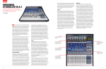
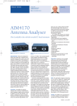
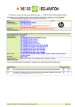
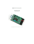
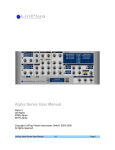
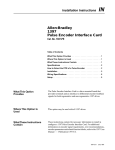
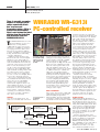
Chris Lorek, G4HCL
REVIEW
PO Box 400, Eastleigh SO53 4ZF.
E-mail: [email protected]
There is currently a growing
number of software-based
radios around with ‘black
box’ receivers and
transceivers using a PC for a
virtual front panel control.
Chris Lorek reviews the latest
offering from the Australian
firm of Rosetta Labs: the
WiNRADiO WR-G313i.
WiNRADiO WR-G313i
PC-controlled receiver
T
he WiNRADiO WR-G313i is a PC
plug-in multimode receiver on a
PCI card, covering 9kHz to
30MHz with an option of frequency
extension to 180MHz. It’s described
as a high-performance HF receiver
intended for government, military,
security, surveillance, broadcast monitoring, industrial and demanding
consumer applications.
Unlike its cousin the G303, the
G313i has its own on-board Digital
Signal Processor, which fully performs the final stage IF filtering and
audio demodulation and doesn’t rely
on the PC sound card for processing.
This of course means that you can
use the sound card with appropriate
software for other applications, like
data and SSTV decoding, further DSP
processing such as noise reduction,
and so-on. Also, if you really want
you can of course use multiple G313i
receivers in a single PC enclosure.
The receiver card simply plugs into
any available PCI slot inside your PC,
and on the rear is a small SMA
antenna socket, together with a
3.5mm audio output socket to feed
either amplified speakers or of course
your sound card input. The package
includes the receiver card, Windowsbased software, a start-up antenna
consisting of a terminated coax lead
connected to a length of insulated
wire, and a user’s manual.
CIRCUITRY
Up to the demodulator stage, the
radio uses a normal dual-conversion
The G313i is a plug-in
PCI card with an SMA
antenna socket and
audio output socket
provided
Fig 1: Block diagram of
the WiNRADiO
WR-G313i.
superheterodyne approach, with an
analogue front-end stage followed by
a mixer down to a first IF of 45MHz
with a synthesiser-derived mixer
injection signal. See Fig 1. At the first
IF two four-pole 15kHz wide crystal
filters are used together with a variable gain amplifier, followed by an
analogue mixer down to the second IF
of 16kHz nominal (12 – 22kHz variable). Here, the signal is further
amplified and AGC (Automatic Gain
Control) and S-meter signal levels are
derived, before the signal is passed to
a 16-bit A/D (Analogue to Digital)
converter sampling at 64kHz. From
henceforth the DSP (Digital Signal
Processor) circuitry steps in to perform the final signal filtering and
demodulation, before being passed to
a D/A converter to provide the final
analogue audio output.
MODES & BANDWIDTHS
The receiver offers modes of CW, LSB,
USB, AM, Synchronous AM, Double
Sideband (DSB), Independent
Sideband (ISB), and narrowband FM,
each with a continuously variable IF
bandwidth of between 1Hz and 15kHz
Fig 1
Front End
• Switchable attenuator
• Switchable filters
• Preamplifier
First IF stage
• Crystal filters
• Variable gain amplifier
+
9kHz to 30MHz
(optionally to 180MHz)
45MHz
DDS & PLL
45.009 to 75MHz
(optionally to 225MHz)
audio
output
DDS & PLL
32.768MHz)
45.016MHz)
D/A converter
Second IF stage
• Amplifier
• AGC block
• RSSI block
16kHz
(variable 12–22kHz)
Reference
Oscillator
DSP
PC
36
+
A/D converter
in 1Hz increments. As well as this
there’s a variable bandwidth IF notch
filter and a switchable noise blanker
with a fully variable threshold setting. There’s a ‘real time’ 20kHz
spectrum display with a 16Hz resolution, and a calibrated analoguestyle S-meter display shows the
received signal level in S-units, dBm
level, or µV, down to the noise floor
of around -140dBm. As well as a
built-in audio recorder you can also
record the 20kHz wide IF spectrum,
which lets you then experiment with
various playback receive modes and
filter widths etc. Together with the
real-time analyser the receiver can
also display a wide-band spectrum
analysis by fast sweeping the receiver across the required range. This
also provides peak finding, averaging, display storage and retrieval, as
well as a display of minimum and
maximum sweeps as well as a differential display (ie one sweep minus
another) which is useful to see if any
new signals have appeared).
Another feature is a test and
measurement facility, performing
measurements on the received signal
including frequency accuracy, amplitude modulation depth, frequency
deviation, THD (total harmonic distortion) and SINAD. A real-time
audio spectrum analyzer with a 5Hz
resolution can also be displayed. You
can also explore block diagrams of
the demodulator for each mode, and
look at the real-time signals at various stages using two spectrum
analysers and a vector voltmeter.
OPTIONAL PLUG-INS
DRM (Digital Radio Mondiale) is a
non-proprietary digital system for HF
plus medium and long-wave broadcasts, which has the potential of providing almost FM-quality audio. This
can be added as a further purchase
to the G313i as an XRS (Extensible
Radio Specification) plug-in which,
after you’ve installed it, is accessible
very simply as another mode from
the top bar menu.
Another optional plug-in is the
Advanced Digital Suite, which adds a
number of digital processing facilities, including a fax module (for
WEFAX and HF fax) with a scheduler, a NAVTEX decoder again with a
scheduler, Packet radio decoder,
ACARS decoder with a code database, CTCSS and DTMF decoders
March 2005 RadCom www.rsgb.org
REVIEW
with alarms, a signal classifier, an
audio scope with waterfall display, a
signal conditioner with user-defined
filters, and an advanced audio
recorder with pitch shift and speed
control. Again after you’ve installed
the suite, the various modes are
accessible from the top bar menu.
Finally, if you’d like to control your
WiNRADiO from another location,
your office for example, the optional
WR-G313-CSO client / server lets you
do this across all types of computer
networks supporting the TCP/IP protocol, including the Internet. With
this in use, you can listen to your
receiver literally anywhere in the
world.
ON THE AIR
As soon as the card is fitted and you
power-up the PC, it’s automatically
recognised by Windows and you simply load the driver software which
comes on the supplied CD. Then it’s
just a case of attaching an antenna (I
used an SMA to BNC adapter plus a
further BNC to SO-239 adapter here)
and an amplified audio source (I used
a pair of amplified PC speakers) and
tuning in!
At first sight the very comprehensive virtual front panel did look rather
intimidating. I believe the controls
and operating facilities are well in
excess of even the most comprehensive ‘top flight’ amateur-class and
even professional-class receivers, but
I very soon got the hang of using it
with the PC mouse. The main tuning
dial is controlled by the left / right PC
mouse buttons, or I could use the
small up / down buttons below the
main frequency display. I could enter
a frequency directly by using the PC
keyboard, and four switchable VFOs
can be used to store your last-used
frequencies. I found, unlike most
amateur transceivers, these did not
also store the receive mode and bandwidth etc, but for this there are plenty of memory channels available – up
to 1000 in each memory file in fact.
Plenty of pre-set IF filter bandwidths were available, and I could
also manually enter any bandwidth I
wanted and vary this (as with most
functions) by using the appropriate
small on-screen up / down buttons,
or more rapidly by a tiny slider
between the buttons. Likewise with
the IF shift, but here I could also
tune the receiver to another frequency
by simply dragging the entire filter
passband over a peak of a visible signal on the spectrum display, and
‘drag’ the filter edge to vary it as
needed to reduce adjacent interference. The notch filter I found very
useful, especially when a heterodyne
appeared right in the middle of the
signals I was tuned to. Overall I found
www.rsgb.org RadCom March 2005
LABORATORY RESULTS
Measurement methods:
Sensitivity: Input signal level in µV pd to give 12dB SINAD, measured on SSB 2.4kHz bandwidth.
Blocking: Increase in level of interfering unmodulated signal, above 12dB SINAD ref level to cause 6dB degradation in 12dB onchannel signal.
Image Rejection and Spurious Rejection: Difference in level between unwanted and wanted IF image / spurious signal levels, each
giving 12dB SINAD on-channel signals.
Selectivity: Single signal bandwidth, measured in kHz.
Intermodulation Rejection: Increase over 12dB SINAD level of two interfering signals giving identical 12dB SINAD on-channel
third order intermodulation product.
MHz
1.8
3.5
7.0
10.1
14.0
18.9
21.0
24.5
28.0
-3dB
-6dB
-10dB
-20dB
-40dB
-60dB
SENSITIVITY
Signal Level
0.44µV
0.38µV
0.35µV
0.35µV
0.35µV
0.35µV
0.35µV
0.35µV
0.39µV
CW 600Hz
0.61kHz
0.62kHz
0.64kHz
0.66kHz
2.19kHz
5.73kHz
MHz
1.8
3.5
7.0
10.1
14.0
18.9
21.0
24.5
28.0
SELECTIVITY
SSB 2.4kHz
2.43kHz
2.43kHz
2.45kHz
2.47kHz
4.02kHz
7.47kHz
+100kHz
90.5dB
93.7dB
97.8dB
99.2dB
98.1dB
95.7dB
94.8dB
93.2dB
92.3dB
AM 6kHz
6.02kHz
6.03kHz
6.04kHz
6.06kHz
7.56kHz
10.63kHz
BLOCKING AND IMAGE REJECTION
+1MHz
+10MHz
1st Image (+90MHz)
91.0dB
100.1dB
81.6dB
94.9dB
102.1dB
80.8dB
101.7dB
103.9dB
79.4dB
103.8dB
102.0dB
64.4dB
102.0dB
103.9dB
64.5dB
102.4dB
101.4dB
66.0dB
102.2dB
101.6dB
66.2dB
101.8dB
102.2dB
66.5dB
102.4dB
101.0dB
65.9dBa
INTERMODULATION REJECTION
5kHz spaced signals:
68.8dB
10kHz spaced signals:
73.5dB
20kHz spaced signals:
blocking limited
40kHz spaced signals:
82.1dB
SPURIOUS REJECTION
(Measured with receiver tuned to above 7.3MHz)
11.25MHz:
61.5dB
15.0MHz:
82.1dB
somewhat. Likewise close-in blocking
and intermodulation was affected by
phase noise, but this was arguably no
worse than many other receivers.
Within the 15 / 20kHz first IF bandwidth filtering the lack of narrower ‘up
front’ IF crystal filtering was evident. At
greater frequency separations the
blocking performance was excellent, in
fact pushing the limits of the cavitytuned signal generators I use. There
were only a couple of spurious receive
responses, at 11.25MHz and 15MHz,
which appeared no matter what frequency the receiver was tuned to.
the filter and notch slopes to be very
steep indeed, a classic ‘brick wall’
response! I did, however, often find
strong adjacent signals induced some
‘raspiness’ to the on-channel received
signals and often there was also audible ‘clicking’ on fast-rising signals such
as strong SSB or CW, probably due to a
delay in AGC attack time. But even so,
overall the receiver gave a very good
account of itself, with certainly at least
as good on-air performance of a similarly-priced hardware offering, but with
the G313i having vastly more operating
features.
LAB TESTS
My measured results are given in the
accompanying table. Of note is the very
good IF DSP filtering down to several
tens of dB, below this synthesiser
phase noise came into effect to widen it
Above: The main
receiver panel
display, showing
the selected signal
frequency and IF
bandwidth.
CONCLUSIONS
After using and testing the receiver, my
overall thoughts were “I’m impressed”.
The WR-G313i has a technical performance matching that of conventional
receivers in its price class, but with the
operational versatility of professional
receivers costing £5000 or more. I’m
sure it will have many happy and very
well satisfied owners.
Of note is that the operating software
is constantly being updated and is
freely available from the WiNRADiO
website, giving a considerable degree of
‘future-proofing’ to a purchased receiver
– in fact I downloaded an update to
improve the operation even more during
the review period.
Our thanks go to Radixon Ltd in
Evesham for the loan of the review
equipment. ♦
37