1
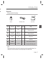
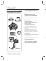
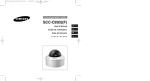
SCC-B5397 SCC-B5399 FRC user manual ENG ENG DIGITAL COLOR DOME CAMERA SPA-M JAP Thank you for purchasing this Samsung product. To receive more complete service, please register your product at www.samsungsecurity.com POR-B imagine the possibilities Safety information 1. CAUTION RISK OF ELECTRIC SHOCK. DO NOT OPEN CAUTION: TO REDUCE THE RISK OF ELECTRIC SHOCK, DO NOT REMOVE COVER (OR BACK) NO USER SERVICEABLE PARTS INSIDE. REFER SERVICING TO QUALIFIED SERVICE PERSONNEL. 2. 3. This symbol indicates that dangerous voltage consisting a risk of electric shock is present within this unit. CA This exclamation point symbol is intended to alert the user to the presence of important operating and maintenance (servicing) instructions in the literature accompanying the appliance. 2. 1. 3. WARNING • To prevent damage which may result in fire or electric shock hazard, do not expose this appliance to rain or moisture. 4. WARNING 5. 1. Be sure to use only the standard adapter that is specified in the specification sheet. Using any other adapter could cause fire, electrical shock, or damage to the product 6. 2. Incorrectly connecting the power supply or replacing battery may cause explosion, fire, electric shock, or damage to the product. 3. Do not connect multiple cameras to a single adapter. Exceeding the capacity may cause abnormal heat generation or fire. 4. Securely plug the power cord into the power receptacle. Insecure connection may cause fire. 5. When installing the camera, fasten it securely and firmly. A falling camera may cause personal injury. 6. Do not place conductive objects (e.g. screwdrivers, coins, metal things, etc.) or containers filled with water on top of the camera. Doing so may cause personal injury due to fire, electric shock, or falling objects. 7. Do not install the unit in humid, dusty, or sooty locations. Doing so may cause fire or electric shock. 2 – DIGITAL COLOR DOME CAMERA 7. 8. 9. S er 1. If any unusual smells or smoke come from the unit, stop using the product. In such case, immediately disconnect the power source and contact the service center. Continued use in such a condition may cause fire or electric shock. 2. If this product fails to operate normally, contact the nearest service center. Never disassemble or modify this product in any way. (SAMSUNG is not liable for problems caused by unauthorized modifications or attempted repair.) 3. When cleaning, do not spray water directly onto parts of the product. Doing so may cause fire or electric shock. CAUTION 1. Do not drop objects on the product or apply strong shock to it. Keep away from a location subject to excessive vibrationor magnetic interference. 2. Do not install in a location subject to high temperature (over 50°C), low temperature (below -10°C), or high humidity. Doing so may cause fire or electric shock. 3. If you want to relocate the already installed product, be sure to turn off the power and then move or reinstall it. 4. Remove the power plug from the outlet when then there is a lightning. Neglecting to do so may cause fire or damage to the product. 5. Keep out of direct sunlight and heat radiation sources. It may cause fire. 6. Install it in a place with good ventilation. 7. Avoid aiming the camera directly towards extremely bright objects such as sun, as this may damage the CCD image sensor. 8. Apparatus shall not be exposed to dripping or splashing and no objects filled with liquids, such as vases, shall be placed on the apparatus. 9. The Mains plug is used as a disconnect device and shall stay readily operable at any time. English – 3 ENG nt Safety information Safety information WARNING 1. Read these instructions. 2. Keep these instructions. 3. Heed all warnings. 4. Follow all instructions. 5. Do not use this apparatus near water. 6. Clean only with dry cloth. 7. Do not block any ventilation openings. Install in accordance with the manufacturer’s instructions. 8. Do not install near any heat sources such as radiators, heat registers, or other apparatus (including amplifiers) that produce heat. 9. Do not defeat the safety purpose of the polarized or grounding-type plug. A polarized plug has two blades with one wider than the other. A grounding type plug has two blades and a third grounding prong. The wide blade or the third prong is provided for your safety. If the provided plug does not fit into your outlet, consult an electrician for replacement of the obsolete outlet. 10.Protect the power cord from being walked on or pinched particularly at plugs, convenience receptacles, and the point where they exit from the apparatus. 11.Only use attachments/accessories specified by the manufacturer. 12.Use only with cart, stand, tripod, bracket, or table specified by the manufacturer, or sold with the apparatus. 13.Unplug this apparatus when a card is used. Use caution when moving the cart/ apparatus combination to avoid injury from tip-over. 14.Refer all servicing to qualified service personnel. Servicing is required when the apparatus has been damaged in any way, such as powersupply cord or plug is damaged, liquid has been spilled or objects have fallen into the apparatus, the apparatus has been exposed to rain or moisture, does not operate normally, or has been dropped. 4 – DIGITAL COLOR DOME CAMERA nd ve or Introduction Features Product & Accessories Part Names and Functions 6 7 8 Installation Before installation Installation procedure Adjusting the camera direction 11 11 13 ENG e Contents How to use OSD Menu Using Icons in the Menu Main Menu Profile Camera Setup Intelligence Privacy Zone Setup Other Set System Information Language 14 14 15 17 25 27 28 29 29 Specifications Specifications 31 English – 5 Introduction FEATURES ❖ High Resolution • This camera has realized high resolution of 600 lines using the top-notch full digital image processing and special algorithm technologies. ❖ VPS(Virtual Progressive Scan) • This is an advanced technology that reproduces a sharp progressive image. This is appropriate to high quality recording and file transfer via the Internet. ❖ Intelligent Motion Detection & Tracking • This is an intelligent function that automatically detects a motion of an object. You can set a virtual fence so it displays an alert if an object passes / enters /exits the virtual fence or virtual area. ❖ WDR • WDR extends the contrast range as it takes a picture of each of dark and bright areas before compositing the two, which is useful if you take a picture of windows inside a building. Namely, it improves the picture quality of the outdoor scenery as well as indoor. ❖ XDR (eXtended Dynamic Range) • Actively controls the gamma compensation in the way it operates the ambient luminance contrast in a certain pixel unit to determine the optimal visibility. ❖ DAY/NIGHT • This function can make the IR Cut filtering function inactive under the illumination below the normal value. ❖ High Sensitivity • It implements images of high sensitivity using the up-to-date SONY Super-HAD Progressive CCD. ❖ Low Illumination • It uses the digital signal technologies such as low illumination and Day/Night functions that make your camera identify objects even in the worst environment. ❖ Superior Backlight Adjustment • When an object has a bright illumination or sunlight behind it, this camera automatically improves the shaded object picture quality. ❖ Digital Power Synchronization • The full digital Line Lock function directly adjusts the vertical camera synchronization to enhance the operationability and reliability of this camera. ❖ Output Signal Setting • You can set the following Video output signals: Image reversion (Horizontal, Vertical, or both), Privacy, Horizontal/Vertical profiling, and digital zooming. ❖ OSD(On Screen Display) Menu • OSD menu is provided to display the status of camera and to configure the functions interactively. ❖ Coaxial Cable Communication • This is a remote control function that overlaps the coaxial cable (for a transfer of the video signal) with the control signal. In installation or repair, this helps you control the communication controller (optional) without additional cabling. 6 – DIGITAL COLOR DOME CAMERA C Introduction Components Checking components in the package Camera Test Monitor Cable User’s Guide f ENG e Image f s Part name Standard Quantity Usage Plastic anchor HUD 5 4 (EA) Attach each piece to screw connection holes for strengthening connection ASSY screw machine BH M5 X L6. (White+o-ring) 8 Used for filling in the holes when installing pipe and wall mount ASSY screw tapping TH M4xL30 (Black+ o-ring) 4 Used when installing your camera on the ceiling or wall。 L-Wrench TROX T-20 1 Used for assembling/disassembling the Dome cover 1 Used for guiding the installation T2.5 W56 1 Used to make a wiring hole when installing the camera on the ceiling or wall Template Gasket-pipe hole –NOTE –The test monitor cable is used to test the camera by connecting to a portable display. If you really want to connect the camera to a monitoring display, use the BNC cable.。 English – 7 Introduction 1.Dome cover: Covers the inner cover, lens, and Components of your camera Your camera has the following components: main body to protect them. ❖ 2.Cover screw: Use it to assemble or disassemble both dome cover and case. 1 3.Inner cover: Covers the main body to protect it. 4.Wing locker: Push a long thin screwdriver into 3 2 4 5 7 6 6 7 8 its narrow spot and press it outward when you want to remove the inner cover. 5.Main body: Includes a lens, a switch board, a PCB board, screws, and such. 6.Screws for assembly and disassembly: Using these 2 screws, the Main body is closely connected to the Case. 7.Hooker: By pulling the left/right levers in the arrow direction, the Main body can be detached from the Case. 8.Case: Used as a ceiling or wall fixture. It is fixed using four screws provided in the package. 9.Zoom lever: Using this lever, the lens zoom can be adjusted and fixed. 10.Focus lever: Using this lever, the lens focus can Lens be adjusted and fixed. 11.Tilt fixing screw: Using this screw, the slope of the lens can be adjusted and fixed. 9 12.Cable: Connect the Video connector to BNC 10 cable and Power connector to power adapter. 11 12 Video connector Power connector 8 – DIGITAL COLOR DOME CAMERA • Introduction ❖ Setting switches ENG • SETUP Switch This switch is used to set the function or property. When this switch is pressed for at least 2 seconds, the MAIN MENU appears. ef (Left/Right) : By pressing this switch left or right, you can move left or right on the menu or change the displayed value. cd (Up/Down) : By pressing this switch up or down, you can move up or down on the menu. : When you press this switch in the menu, the selected function is confirmed. To enter a submenu, press this button. English – 9 Installation I Installing camera Before installation Before installing your camera, you have to read the following cautions: You have to check whether the location (ceiling or wall) can bear five times the weight of your camera. Don’t let the cable to be caught in improper place or the electric line cover to be damaged. Otherwise it may cause a breakdown or fire. You can use wall mount adaptor (SADT-102WM), and pole mount adaptor (SADT100PM) for installing the camera on the wall or pipeline. When installing your camera, don’t allow any person to approach the installation site. If you have any valuable things under the place, move them away. Be are To 1. About the installation holes Bottom of camera A B C A:Use these holes when directly installing your camera on the ceiling or wall. While those are not used, fill in the holes using the screw machine (M5 X L6.) for waterproofing. B: Use four holes when directly installing your camera on the junction box You can use the 4 1/8 diameter round type junction box for assembly. (The junction box, gasket, and cover are separately purchased items.) C:Use these holes when installing the wall mount adapter (SADT-102WM) While those are not used, fill in the holes using the screw machine (M5 X L6.) for waterproofing. The holes that are not used should be tightly sealed up using the screws provided for waterproofing. When the screws don’t have rubber rings inside or are not closely attached, note that it can cause waterproofing problem. 10 – DIGITAL COLOR DOME CAMERA 2. n y - e Installation Installing on a pipe Before installation, you have to be familiar with the above cautions and fill in the holes that are not used for installation. To install your camera bottom on a pipe 1. After connecting the power and video cables, throw them inside the pipeline and screw the male thread pipe into the female pipe thread in your camera tightly to fix the Main body. (In this case, be sure to tape with Teflon tape before assembly for waterproofing. Be careful for the wiring cable not to be stuck in the connection area.) 3. Attach the Dome cover. (Screw the connection bolts tightly using the L-Wrench for waterproofing.) To change the SAMSUNG logo position, move the location of the connection rubber band as show below and rotate for assembly. (The rotation limit is 180 degree.) g 5 ENG n y. ) 5 2. Adjust the angle of the camera in search of a better view. 1) Separate the Dome cover using the L-Wrench provided. (To make loose the screws, rotate counterclockwise.) 2) Adjust the lens direction. For more information, see page 17 “Adjusting the camera direction.” English – 11 Installation H Adjusting the camera direction When the camera is fixed on the ceiling, you can adjust the camera viewing angle. You can rotate your camera leftward or rightward (Panning), and can change the slope of your camera upward or downward (Tilting). In case of panning, the rotation limit of your camera is set to 355 degree (100 degree clockwise and 255 degree counterclockwise). The rotation is stopped by the Stopper inside of the camera. For panning control, first unfasten two screws located on the bottom and rotate in the direction you want, and then fasten them to fix the camera. In case of tilting, you can change the slope of your camera from zero to 90 degree. However if the slope angle is under 17 degree, you can encounter a partial image hide problem. To fix the location after adjusting the tilting angle, use the Tilt fixing screws. To adjust the focus and zoom of your camera, use the Zoom lever and Focus lever. When you install the camera on the inclined ceiling or wall, you can rotate the camera lens to see a correct direction image. U • • • • Panning • Tilting Lens rotation 12 – DIGITAL COLOR DOME CAMERA e. e 0 by ws to e. e g USING ICONS IN THE MENU • (EXIT) Exits the menu setting. Before you exits the menu setting, select SAVE to save your settings, or select QUIT to cancel. • (RET) Returns to the previous menu. MAIN MENU MAIN MENU PROFILE CAMERA SET INTELLIGENCE PRIVACY ZONE OTHER SET SYSTEM INFO LANGUAGE • (HOME) Returns to the main menu. • (SAVE) Used to save your settings of MASK AREA, PRIVACY ZONE and more. Once you save your settings, they will remain even if you select QUIT in the menu. • (DEL) Used to deletes your settings of MASK AREA, PRIVACY ZONE and more. Once you delete your settings, they will not be restored even if you select QUIT in the menu. • PROFILE You can set a mode according to the camera installation conditions. • CAMERA SET Configure Camera related functions and data. • INTELLIGENCE You can configure the settings of motion detection, tracking and more. • PRIVACY ZONE You can configure the privacy related settings. • OTHER SET You can configure for Factory Defaults, and more. • SYSTEM INFO. Displays the system information including the camera version and communication settings. • LANGUAGE Select a preferred one from the supported languages. English – 13 ENG us e How to use OSD Menu How to use OSD Menu PROFILE ePROFILEf STANDARD ITS BACKLIGHT DAY/NIGHT GAMING CUSTOM D W In the PROFILE menu, you can configure the following camera settings at once. CAMERA SET Menu Previous Sub-menus Menu VPS IRIS ALC LENS LEVEL BACKLIGHT WDR WEIGHT WDR LEVEL WHITE BAL MOTION DNR STANDARD ITS BACKLIGHT DAY/NIGHT GAMING OFF ALC DC 0 OFF User setting allowed User setting allowed User setting allowed (F.FAST)--MID ON ALC DC 0 OFF User setting allowed User setting allowed User setting allowed (F.FAST)--MID OFF ALC DC 0 WDR - OFF ALC DC 0 OFF User setting allowed User setting allowed User setting allowed (F.FAST)--MID OFF ALC DC 0 OFF User setting allowed User setting allowed User setting allowed SLOW MID MID 0 User setting allowed NORM MID ❖ ❖ ❖ ❖ 14 – DIGITAL COLOR DOME CAMERA How to use OSD Menu BRIGHTNESS MODE RED BLUE DETAIL STANDARD ITS BACKLIGHT DAY/NIGHT GAMING OFF AUTOx4 MID AUTO OFF DAY ATW2 0 0 User setting allowed OFF User setting allowed User setting allowed 2 AUTO1/250 AUTOx2 MID AUTO ON DAY/NIGHT ATW1 0 0 - OFF AUTOx4 MID DAY OFF DAY ATW1 0 0 User setting allowed OFF User setting allowed User setting allowed 2 OFF AUTOx4 MID AUTO OFF DAY/NIGHT ATW1 0 0 - OFF AUTOx4 MID DAY OFF DAY ATW1 0 0 User setting allowed OFF User setting allowed User setting allowed 2 MID ATW2 0 0 2 MID ATW2 0 0 2 ❖ ITS It will be set automatically so you can easily check the traffic conditions. ❖ BACKLIGHT It will be set automatically so you can distinguish the object from the background in a severe backlighting scene. ❖ DAY/NIGHT It will be set automatically so it optimizes to the day or night conditions, respectively. ❖ GAMING English – 15 ENG CAMERA SET Menu Previous Sub-menus Menu SHUTTER SENS-UP XDR DAY/NIGHT NIGHT BURST WHITE BAL DAY MODE RED BLUE NIGHT How to use OSD Menu Setup the general functions of zoom camera module. CAMERA SETUP Use the cdef switch to select a menu item. eCAMERA SETf CAMERA ID OFF VPS OFF IRIS ALC MOTION (F.FAST)--DNR MID SHUTTER OFF SENS-UP AUTO X4 FLICKERLESS (OFF)--XDR MID d ❖ CAMERA ID CAMERA ID ABCDEFGHIJKLMNOPQRSTUVWXYZ0 123456789 :?-+*()/ SPffeeSP LOCATION CAMERA-1.................. ........................... c DAY/NIGHT AUTO WHITE BAL DIGITAL ZOOM OFF DETAIL [2] V-SYNC INT AGC COLOR SUP LOW REVERSE H/V POSI/NEGA + PIP OFF d c DIS OFF 16 – DIGITAL COLOR DOME CAMERA The CAMERA ID menu is used for you to assign a unique name to a camera. If you press the SETUP switch with the CAMERA ID menu selected, you will see the appropriate screen. You can enter up to 54 alphanumeric or special characters for the CAMERA ID. Select LOCATION and press the SETUP switch to move the display position of the CAMERA ID. ❖ VPS [OFF, ON] If you set the VPS (Virtual Progressive Scan) option, the camera will display the image in progressive format. ❖ IRIS [OFF, ON] [ALC] The IRIS menu is used if you want to adjust the intensity of radiation incoming to the camera. • e. • ALC (Automatic Light Control) ① If you press the SETUP switch with an ALCbased sub menu selected, you will see the appropriate screen. ALC LEVEL BACKLIGHT [00]----I---OFF If you use an ordinary camera in a scene with an intensive backlight, the object will be displayed dark on the monitor affected by the backlight. To solve this problem, you can use the BLC(Back Light Compensation) function to improve the sharpness of the image in such a high contrast scene. ③ If you set the BACKLIGHT option to WDR, you will see a menu where you can set the WDR options. You can adjust the shutter speed in WDR LEVEL and the brightness in WEIGHT. The LEVEL menu is used to adjust the overall brightness, where “+” will increase the brightness and “–” will decrease it. ② If you set the BACKLIGHT option to BLC, you will see a menu where you can set the BLC area. you can set the desired BLC zone by defining the size and location. ALC LEVEL [00]----I---BACKLIGHT BLC AREA USER <SIZE> <LOCATION> You can also select any of OUTDOOR, and INDOOR in WHITE BAL. ALC LENS DC LEVEL [ 00]----I---BACKLIGHT WDR WEIGHT MID WDR LEVEL [ 0]----I---WHITE BAL INDOOR WDR(Wide Dynamic Range) extends the gain range of the screen that is mostly useful if you take a simultaneous picture of both indoor and outside of the window. Namely, it improves the sharpness of the picture in outdoor scenery as well as indoor. Note : – If you use the VPS (Virtual Progressive Scan) function, the CCD reads differently so you can not use WDR simultaneously. If you set VPS to ON, WDR will be automatically set to OFF. English – 17 ENG n How to use OSD Menu How to use OSD Menu ❖ AGC [OFF, VERY LOW, LOW, MID, HIGH, VERY HIGH, USER, FIX] The AGC (Auto Gain Control) menu is used to set the AGC level of the camera. When the AGC is active, the camera automatically increases the sensitivity by amplifying the Video signal when the strength of the signal falls below the normal value. If OFF or FIX mode is selected in the SENS-UP menu, you can specify the AGC level. If you press the SETUP switch with a USER sub menu selected, you will see the appropriate screen. AGC USER LEVEL AGC FIX LEVEL [01] ❖ If you press the SETUP switch with a FIX sub menu selected, you will see the appropriate screen. As a fixed value of the AGC gain is used in FIX mode, you can select one of the 16 detailed levels from VERY LOW to VERY HIGH before fixing it. FIX mode is not available if you set the BACKLIGHT function to WDR. [16] Note : – If the DAY/NIGHT menu of the CAMERA SET is set to AUTO, the AGC menu will be deactivated. – If FLICKERLESS is set to ON, the AGC FIX mode will be disabled. In USER mode, you can break down the level in 16 steps from VERY LOW to VERY HIGH to your preference. ❖ MOTION [S.SLOW, SLOW, NORM, FAST, F.FAST] The MOTION menu is used to adjust the strength of the AGC level for a control of the camera motion. This is available only if the SENS-UP menu is set to AUTO. You can select one from S.SLOW, SLOW, NORM, FAST and F.FAST for the AGC level. If you monitor a fast moving object in a low contrast scene, select F.FAST while select S.SLOW for a hardly moving object in the same lighting condition. 18 – DIGITAL COLOR DOME CAMERA ❖ n. d. ST] n. M, st Note : – If the DAY/NIGHT menu of the CAMERA SET is set to AUTO, the MOTION menu will be deactivated. ❖ DNR [OFF,LOW,MID,HIGH, USER(1~16)] You can configure the DNR (Digital Noise Reduction) related settings. Reduces the noise on the screen. This is especially useful for a severely distorted screen. You can set the level if you set DNR to USER. ❖ SHUTTER [OFF, AUTO 1/100(PAL:1/120), AUTO 1/250, AUTO 1/500, AUTO 1/1000, AUTO 1/2000, AUTO 1/4000, AUTO 1/10K , 1/100(PAL:1/120), 1/250, 1/500, 1/1000, 1/2000, 1/4000, 1/10K , EXT] The SHUTTER menu is used to configure settings of the fixed / auto high-speed electronic shutter. You can select one of 7 options from 1/100(PAL:1/120) to 1/10K for the fixed high speed electronic shutter, which is mostly used for imaging a fast moving object. The auto high speed electronic shutter operates as the fixed high speed shutter in a high contrast scene but automatically focuses the target if the iris opens fully in a low contrast scene like in ELC mode. When it gets brighter back, the mode will switch to the fixed high speed electronic shutter mode. Note : – If the SENS-UP function is set to AUTO, only items of OFF and AUTO are available in the SHUTTER menu. – If the SENS-UP mode is set to FIX, the SHUTTER menu will be deactivated. – If the FLICKERLESS function is set to ON, the SHUTTER menu will be deactivated. ❖ SENS-UP [OFF, AUTO X2, AUTO X4, AUTO X6, AUTO X8, AUTO X12, AUTO X16, AUTO X24, AUTO X32, AUTO X48, AUTO X64, AUTO X96, AUTO X128, AUTO X256, AUTO X512, FIX X2, FIX X4, FIX X6, FIX X8, FIX X12, FIX X16, FIX X24, FIX X32, FIX X48, FIX X64, FIX X96, FIX X128, FIX X256, FIX X512] Automatically detects the ambient level of darkness in the dark or low contrast scene to extend the accumulated time, keeping the image bright and sharp; It can be also used as FIX mode. Note : – If the SHUTTER menu is set to fixed electronic shutter mode, the SENS-UP menu will not be available. – If FLICKERLESS is set to ON, the FIX mode of the SENSUP menu will be disabled. – If the SHUTTER menu is set to AUTO, the SENS-UP menu can be set to either OFF or AUTO mode. – If the BACKLIGHT function is set to WDR, the SENS-UP menu can not be set to FIX. However, the auto high speed shutter operates properly only in a camera featuring a DC or VIDEO lens. n. English – 19 ENG s How to use OSD Menu How to use OSD Menu ❖ FLICKERLESS [OFF, ON] If set to ON, the shutter speed will be fixed to 1/100(PAL:1/120) second. This will prevent possible screen distortion due to a mismatch between the vertical sync frequency and the blinking frequency of the lighting. Note : – If the SHUTTER menu is set to AUTO or FIX mode, the FLICKERLESS menu will not be available. – If the SENS-UP function is set to FIX mode, the Flickerless menu will be deactivated. – If AGC is set to FIX mode, the FLICKERLESS function will be disabled. ❖ XDR (eXtended Dynamic Range) [OFF, LOW, MID, HIGH] Actively controls the gamma compensation in the way it operates the ambient luminance contrast in a certain pixel unit to determine the optimal visibility. Select one from OFF, LOW, MID and HIGH. Closing to HIGH will increase the compensation level. ❖ DAY/NIGHT [DAY,NIGHT,AUTO,EXT] • DAY If set to DAY, it will be fixed to DAY mode regardless of the ambient conditions. • NIGHT If set to NIGHT, it will be fixed to Black-and-White mode regardless of the ambient conditions. 20 – DIGITAL COLOR DOME CAMERA If you press the SETUP switch with a NIGHT sub menu selected, you will see a menu where you can set Burst to OFF/ON. If BURST is set to ON, the Burst signal will output together with the black-and-white composite video signal. If BURST is set to OFF, the Burst signal does not output. You can set the BURST option to OFF/ON, or select to output the Burst signal in NIGHT mode. • AUTO The camera will automatically switch between DAY and NIGHT mode, according to the lighting condition. If you press the SETUP switch with an AUTObased sub menu selected, you will see the appropriate screen. AUTO BURST DAYÆNIGHT BRIGHTNESS DWELL TIME NIGHTÆDAY BRIGHTNESS DWELL TIME MASK AREA OFF MID 2S 1 MID 5S 2 You can set the BURST option to OFF/ON, or select to output the Burst signal in NIGHT mode. The BRIGHTNESS of DAYÆNIGHT sets the brightness degree of color to BW switching, for which you can select from LOW, MID, and es e. HIGH. As you adjust it from HIGH to LOW, the screen switches to black and white mode under the darker situation. DWELL TIME of DAYÆNIGHT sets the time to maintain switched black and white mode. The BRIGHTNESS of NIGHTÆDAY sets the brightness degree of BW to color switching, for which you can select from LOW, MID, and HIGH. As you adjust it from HIGH to LOW, the screen switches to color mode under the darker situation. DWELL TIME of NIGHTÆDAY sets the time to maintain switched color mode. The MASK AREA menu is used to prevent unintended mode switching or inability of determining the switching due to existence of high spot light source at night. If you press the SETUP switch in item 1 or 2 of the MASK AREA menu, you will see a menu where you can specify an area to MASK. The MASK is only for determining the mode switching, and any excessive bright area at night will be excluded by the configured MASK. Note : – If BACKLIGHT is set to BLC, the MASK AREA function will be deactivated. • DAY This enables an auto switch between DAY and NIGHT mode using the interface with the external sensor. ❖ WHITE BAL [DAY/NIGHT] If you want to adjust the color scheme, use the WHITE BALANCE function. • DAY In DAY mode, you can set the color values of RED and BLUE. The screen will be displayed in colors according to your settings. WHITE BAL DAY/NIGHT MODE RED BLUE R-GAIN B-GAIN MASK AREA <SIZE> <LOCATION> DAY AWC [00]----I---[00]----I---[0248] [0247] You can specify MASK 1 and 2 simultaneously. Note : – You can set the values of R-GAIN and B-GAIN only in AWC mode. English – 21 ENG g How to use OSD Menu How to use OSD Menu • NIGHT Use the NIGHT mode if you want to set the white balance differently according to the ambient luminance. If the NIGHT mode is set to OFF, the white balance will always operate as set in DAY mode; if not to OFF, the camera will switch to as set in DAY/NIGHT mode according to the brightness. In NIGHT mode, you can set the values of RED, BLUE and BRIGHTNESS. The screen will be displayed in colors according to your settings. WHITE BAL DAY/NIGHT BRIGHTNESS MODE RED BLUE R-GAIN B-GAIN NIGHT MID AWC [00]----I---[00]----I---[0248] [0247] Note : – You can set the values of R-GAIN and B-GAIN only in AWC mode. – If AGC is set to OFF or FIX, you can not access the NIGHT menu. – For adjusting the white balance, the following 5 modes are provided: • ATW1(Auto Tracing White Balance mode 1): The camera can automatically adjust the color temperature in real time, according to 22 – DIGITAL COLOR DOME CAMERA – – – – the ambient conditions. The color temperature ranges from approx. 2500K to 9300K. • ATW2: The color temperature ranges from approx. 2,000K to 10,000K. • AWC ( Auto White Balance Control): If you press the SETUP switch in the appropriate item position, Auto White Balance will perform once. • 3200K : Set color temperature to 3200K • 5600K : Set color temperature to 5600K RED : Adjusts the strength of the red color. BLUE : Adjusts the strength of the blue color. R-GAIN/B-GAIN : Enables you to set the current color temperature manually. BRIGHTNESS : Select a brightness level in switching from setting in DAY mode to setting in NIGHT mode. ❖ DIGITAL ZOOM -L c r e [ON/OFF] You can set the digital zoom factor and position. If you press the SETUP switch with the DIGITAL ZOOM function set to ON, you will see the appropriate screen. When the zoom factor and position are defined, the digital zoom function will operate. ❖ ❖ How to use OSD Menu e Note : DIGITAL ZOOM – Use of DC 12V will fix V-SYNC to INT, which can not be RATIO [X1.0] < LOCATION > changed. ❖ AGC COLOR SUP ❖ REVERSE Note : – If the digital zoom factor is set to larger than 1x, the FENCE function will be deactivated. The DIGITAL ZOOM function enlarges the pixel itself, which can cause deterioration of the quality. ❖ DETAIL [0~3] Controls the horizontal or vertical distinction. ❖ V-SYNC [INT, LINE] Select the vertical sync mode for INT or LINE. If you select INT, the camera will use the internal synchronization. If selecting LINE, the camera will use the external power source frequency for the synchronization. You can adjust the LL-PHASE. [+, -] Output as it is or mirror the video brightness signal. ❖ PIP [OFF, ON] Displays a sub image together with the main image on the same screen using the Picture In Picture function. Note : – If more than one privacy zone is set and the PRIVACY SET is set to ON, the PIP function will be deactivated. – If the INTELLIGENCE function is set to FENCE mode, the PIP menu will be deactivated. ❖ DIS [OFF, ON] Digital Image Stabilization will set the anti-shake compensation. Note : – If you set DIS to ON, the compensation area will be enlarged as set in the digital zoom factor. If you set the digital zoom factor to greater than the enlarged zoom factor for the compensation, the DIS function will be deactivated. English – 23 ENG . L - LOCATION : If you press the SETUP switch in the condition where the image is enlarged as much as the ratio setting, you can watch an invisible area of the effective screen as well using the cdef switch. [OFF, H, V, H/V] Mirrors video signals horizontally, vertically, or both. ❖ POSI/NEGA t [LOW , MID, HIGH] Adjust the color scheme according to the AGC value. m e. How to use OSD Menu • FENCE INTELLIGENCE eINTELLIGENCEf MOTION ADVANCED MASK AREA DISPLAY SENSITIVITY RESOLUTION 1 OFF OFF 2 3 4 ON [4] [5] This is to detect if a moving object passes through the specified LINE or AREA. In a condition where a moving object is detected in an analysis of the previous and current frames whose movement overlaps a certain area, the system displays “PASS” if the object’s center line passes through the line while it displays “ENTER” or “EXIT” if the center point passes through the area. FENCE LINE AREA You can set the motion detection and tracking in the INTELLIGENCE menu. While this camera includes the Intelligent Video feature, it does not have an alarm output. This function will allow you to demonstrate/ review only of the technology. ❖ MOTION [OFF,TRACKING,DETECTION] • TRACKING Detects and tracks a moving object. • DETECTION Detects a moving object. Note : – If it is set to DETECTION, you can not set such functions as FIXED/MOVED and FENCE in the ADVANCED menu. ❖ ADVANCED OFF OFF You can set the position and detection direction of the LINE, and the size and position of the AREA. - How to set the line LINE PIXEL LEVEL <POINT> DIRECTION [4] §¨ [OFF, FIXED/MOVED, FENCE] Detects a motion of an object and displays an image of any moving object before tracking the moving route. 24 – DIGITAL COLOR DOME CAMERA or How to use OSD Menu ① If you press the SETUP switch with the LINE option set to ON, you can specify the position and detection direction of the line. ② If you change the PIXEL LEVEL for setting the position, specify the pixel that moves by a single pressure of the cdef switch. ④ If you change the DIRECTION, you can specify the detection direction. The detection direction based on the defined two points will be displayed on the screen. - How to set the area e AREA PIXEL LEVEL <SIZE> <LOCATION> ③ In <SIZE>, press the SETUP switch and use the cdef switch to adjust the size. Press the SETUP switch again to complete the sizing. ④ In <LOCATION>, press the SETUP switch and use the cdef switch to specify the position. Press the SETUP switch again to complete the positioning. Note : – If you set the LINE of the FENCE to ON, PRIVACY 12 will not be available. Functions of FENCE, PIP, DIS and DIGITAL ZOOM (if the digital zoom factor is set to larger than 1x) can not be used simultaneously. – In the boundary of the defined AREA and LINE, a FENCE detection error may occur if two or more moving objects overlap with each other or one object separates in multiple directions. [4] • FIXED/MOVED ① If you press the SETUP switch with the AREA option set to ON, you can specify the position If an object on the screen suddenly disappears or an object comes out of nowhere and stays for a certain time, the area will be displayed. A detection (FIXED/MOVED) error may occur if : - multiple motions occur continuously in random directions English – 25 ENG ③ In <POINT>, you can specify the first position of the line by pressing the SETUP switch once, and the second position by pressing the switch again. Use the cdef switch to specify the position. Set each position of the two points and press the SETUP switch to complete the positioning. and size of the area. ② If you change the PIXEL LEVEL for setting the position, specify the pixel that moves by a single pressure of the cdef switch. How to use OSD Menu - a fixed object moves in one position continuously - a second object screens the first moving object PRIVACY ZONE SETUP Us PR ePRIVACY ZONEf ❖ MASK AREA [1~4] Specify a detection exception area to mask. Select a mask number and specify the size and position. 1 7 2 8 3 9 4 10 PRIVACY SET STYLE 5 11 6 12 ON MOSAIC1 MASK AREA <SIZE> <LOCATION> ❖ DISPLAY [1~7] Set the sensitivity of the motion detection. ❖ RESOLUTION The PRIVACY function will protect your privacy by screening the privacy area that you have specified during monitoring. You can specify up to 12 privacy zones. If you set the PRIVACY SET to ON, your PRIVACY ZONE settings will be applied. [ON, OFF] With the DISPLAY option set to ON, a motion or a set ADVANCED function will be displayed on the screen, if detected. ❖ SENSITIVITY [1~5] If setting it to high, the camera can detect even a trivial movement of the target. 26 – DIGITAL COLOR DOME CAMERA You can change the style to adjust the mosaic size and color of the PRIVACY ZONE. ePRIVACY ZONEf 1 7 2 8 3 9 PRIVACY SET STYLE Y-LEVEL RED BLUE 4 10 5 11 6 12 ON COLOR [128] [128] [128] Se SE sp LE How to use OSD Menu Use the cdef switch to select one from PRIVACY 1 through 12. Select one from PRIVACY 1~12 and press the SETUP switch to confirm your setting. You can specify a pixel that moves as you change the PIXEL LEVEL to set the position. ② Use the cdef switch to move the position and press the SETUP switch to confirm it. Note : – If more than one PRIVACY ZONE is specified and the PRIVACY SET is set to ON, the PIP function will be deactivated. PRIVACY ZONE SET1 PIXEL LEVEL <POINT> <POSITION> ① By pressing the SETUP switch in <POSITION>, you can move the overall position of the privacy zone. [4] OTHER SET eOTHER SETf - How to set the point You can set each position of the 4 points. ① If you press the SETUP switch in <POINT>, you will see the points available in the PRIVACY ZONE. Each time you press the SETUP switch, the points available will move. ② Use the cdef switch to set the position of each point. Set each position of the four points and press the SETUP switch to complete the positioning. - How to set the position You can move the position of the overall area. EXTERNAL TRG FACTORY DEFAULTS OSD COLOR OFF BW ❖ EXTERNAL TRG Set the EXTERNAL TRG menu to ON and press the SETUP switch to display the appropriate screen. English – 27 ENG – If the 12th PRIVACY ZONE is specified, the LINE function of FENCE will be deactivated. How to use OSD Menu ❖ SYSTEM INFORMATION EXTERNAL TRG STILL TIME DELAY TIME OFF FIX eSYSTEM INFOf TYPE 3_VAR_WDR_N SERIAL NO. 000000000000000 CAMERA VER. 0.50_090101 You can set the STILL TIME to 0~4 seconds. If DELAY TIME is set to FIX, the DELAY TIME will be set in sync with the STILL TIME; if set to USER, the DELAY TIME will be set to your setting. Note : – If VPS is set to OFF, the EXTERNAL TRG menu will be deactivated. You can check the system information such as SERIAL NO and CAMERA VER. LANGUAGE ❖ FACTORY DEFAULTS eLANGUAGEf All the settings will be restored to the factory default. However, the settings of PROTOCOL, BAUD RATE, ADDRESS and LANGUAGE will not be restored to the default. ❖ OSD COLOR [BW, R/G/B] ENGLISH FRANÇAIS ESPAÑOL 日文 INGLÊS You can set the OSD(On-screen Display) color to COLOR or B/W. The camera supports 5 different languages. Select a preferred language. 28 – DIGITAL COLOR DOME CAMERA How to use OSD Menu ❖ Initial Configuration Table • Camera Configuration CAMERA ID OFF VPS OFF IRIS ALC AGC VERY HIGH MOTION DNR (F.FAST) MID OFF SENS-UP AUTO x4 FLICKERLESS (OFF) XDR MID DAY/NIGHT AUTO DIGITAL ZOOM OFF DETAIL [2] AGC COLOR SUP MID REVERSE H/V POSI/NEGA ENG SHUTTER + PIP OFF DIS OFF V-SYNC INT English – 29 Specifications SPECIFICATIONS Items Camera Type Image Scanning Sub-items Horizontal Frequency Vertical Frequency Min. Scene Illumination Functions SCC-B5397N/SCC-5399N CCTV Camera (WDR & DAY/NIGHT) Device 1/3” Super-HAD PS CCD Total 811 x 508 Pixels Effective 768 x 494 System Interlace/Progressive Scanning Line 525 lines Frame 30frame/1sec Internal Mode 15,734 Hz Line-lock Mode Internal Mode Line-lock Mode 15,750 Hz 59.94 Hz 60 Hz Sens-up OFF OFF OFF 512 times 512 times 512 times Condition F No. 1.2 1.2 1.2 1.2 1.2 1.2 Number of Privacy Zone Day/Night Motion Detection eXtended Dynamic Range(XDR) Wide Dynamic Range(WDR) Virtual Progressive Scan(VPS) D-Zoom PIP High Speed Shutter Flickerless 30 – DIGITAL COLOR DOME CAMERA Level 50 30 15 50 30 15 IRE IRE IRE IRE IRE IRE Min. Scene illumination DAY NIGHT 0.4 Lux 0.04 0.24 Lux 0.024 0.12 Lux 0.012 0.0008 Lux 0.00008 0.0005 Lux 0.00005 0.00023 Lux 0.000023 Lux Lux Lux Lux Lux Lux 12 (Polygonal Method) DAY/NIGHT/AUTO/EXT OFF/Tracking/Detection Off/On (Level Setting) Off/On (x128) Off/On x1 ~ x16 (x0.1 STEP) Off/On 1/60 ~ 1/10Ksec (OSD/External Control) Off/On Specifications s Items SCC-B5397N/SCC-5399N Video Output S/N Ratio Sens-Up AGC Line Lock Camera ID White Balance Digital Noise Reduction(DNR) Digital Image Stabilization(DIS) Intelligent Video Etc. Function Horizontal Vertical S/N Ratio x2 ~ x512 Off/On (Max.Level Setting) Off/On (Phase Control) Off/On (Max.54ea/2Line) ATW1/ATW2/AWC/3200K/5600K Off/On (Adaptive 3D+2D) Off/On Fixed/Moved, Fence Detail, Reverse(H/V), Posi/Nega 600 TV Lines 350 TV Lines VBS 1.0Vp-p, 75 Ω Approx. 52dB Lens Lens Drive Type Resolution PAN Range TILT Remote Control Range Auto Iris (DC) SCC-B5397 : focal length = 2.5 to 6.0mm / Aperture ratio = F 1.2 SCC-B5399 : focal length = 2.8 to 11.0mm / Aperture ratio = F 1.2 0 ~ 355°(100° in CW(Clockwise) direction, 255° in CCW (Counterclockwise) direction) 0 ~ 90° Coaxitron (Data On Coax cable) Yes (with SCX-RD100) Environmental Conditions Operating Temperature Humidity -10˚C ~ +50˚C Less than 90% AC24V ± 10%(60Hz ± 0.3Hz) DC12V ± 10% 2.6W 150(Ø) x 121(H)mm Power Power Requirement Power Consumption Dimensions (Ø x H) Physical Specification Weight 980g Color White English – 31 ENG Sub-items Specifications Items Camera Type Image Scanning Sub-items Horizontal Frequency Vertical Frequency Min. Scene Illumination Functions SCC-B5397P/SCC-5399P CCTV Camera (WDR & DAY/NIGHT) Device 1/3” Super-HAD PS CCD Total 795 x 596 Pixels Effective 752 x 582 System Interlace/Progressive Scanning Line 625 lines Frame 25frame/1sec Internal Mode 15,625 Hz Line-lock Mode Internal Mode Line-lock Mode 15,625 Hz 50 Hz 50 Hz Sens-up OFF OFF OFF 512 times 512 times 512 times Condition F No. 1.2 1.2 1.2 1.2 1.2 1.2 Number of Privacy Zone Day/Night Motion Detection eXtended Dynamic Range(XDR) Wide Dynamic Range(WDR) Virtual Progressive Scan(VPS) D-Zoom PIP High Speed Shutter Flickerless Sens-Up BLC 32 – DIGITAL COLOR DOME CAMERA Level 50 30 15 50 30 15 IRE IRE IRE IRE IRE IRE Min. Scene illumination DAY NIGHT 0.4 Lux 0.04 0.24 Lux 0.024 0.12 Lux 0.012 0.0008 Lux 0.00008 0.0005 Lux 0.00005 0.00023 Lux 0.000023 Lux Lux Lux Lux Lux Lux 12 (Polygonal Method) DAY/NIGHT/AUTO/EXT OFF/Tracking/Detection Off/On (Level Setting) Off/On (x160) Off/On Max. x16 Off/On 1/50 ~ 1/10Ksec (OSD/External Control) Off/On x2 ~ x512 Off/On (Area Setting) Specifications Items SCC-B5397P/SCC-5399P Video Output S/N Ratio AGC Line Lock Camera ID White Balance Digital Noise Reduction(DNR) Digital Image Stabilization(DIS) Intelligent Video Etc. Function Horizontal Vertical S/N Ratio Off/On (Max.Level Setting) Off/On (Phase Control) Off/On (Max.54ea/2Line) ATW1/ATW2/AWC/3200K/5600K Off/On (Adaptive 3D+2D) Off/On Fixed/Moved, Fence Detail, Reverse(H/V), Posi/Nega 600 TV Lines 350 TV Lines VBS 1.0Vp-p, 75 Ω Approx. 52dB Lens Lens Drive Type Resolution PAN Range TILT Remote Control Range Auto Iris (DC) SCC-B5397 : focal length = 2.5 to 6.0mm / Aperture ratio = F 1.2 SCC-B5399 : focal length = 2.8 to 11.0mm / Aperture ratio = F 1.2 0 ~ 355°(100° in CW(Clockwise) direction, 255° in CCW (Counterclockwise) direction) 0 ~ 90° Coaxitron (Data On Coax cable) Yes (with SCX-RD100) Environmental Conditions Operating Temperature Humidity -10˚C ~ +50˚C Less than 90% AC24V ± 10%(50Hz±0.3Hz) DC12V ± 10% 2.6W 150(Ø) x 121(H)mm 980g White Power Physical Specification Power Requirement Power Consumption Dimensions (Ø x H) Weight Color English – 33 ENG Sub-items