1
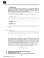
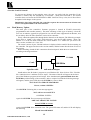
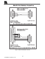
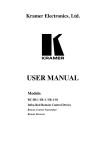
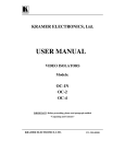
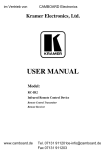
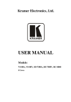
KRAMER ELECTRONICS, Ltd.
USER MANUAL
Master Programmable Remote Control
Model:
VS-3000
IMPORTANT: Before proceeding, please read paragraph entitled
"Unpacking and Contents"
Table Of Contents
Section
1
1.1
1.2
2
3
4
4.1
5
5.1
6
6.1
7
7.1
7.2
7.3
7.4
7.5
8
8.1
8.2
8.2.1
8.2.2
8.2.3
8.2.4
8.3
8.4
8.5
9
10
10.1
10.2
10.3
Name
INTRODUCTION
A Word on Video/Audio Switchers
Factors Affecting Quality of Results
SPECIFICATIONS
HOW DO I GET STARTED?
UNPACKING AND CONTENTS
Optional Accessories
KRAMER VS-3000 REMOTE CONTROLLER
Getting To Know Your VS-3000 Remote Controller
INSTALLATION
Rackmounting
CONNECTING TO OTHER DEVICES
Connecting to a PC
Connecting to a video Matrix or other Controlled Devices
Connecting to the an RS-485 Controlled machine or Controller
Connection to a Dry Contact Controlling Device
Connecting the Keyboard Extension
USING THE VS-3000
Turning On the VS-3000
Using the Front Panel Controls
Key Assignments
LCD Assignments
Setup
Setup – List of Machines
Menu Functions
Flash Memory Update
Error Messages
TAKING CARE OF YOUR MACHINE
TROUBLESHOOTING
Power and Indicators
HUM and Electric Interference
Control Related Problems
Limited Warranty
Page
2
2
2
3
3
3
3
5
5
6
6
6
6
6
7
7
7
7
7
7
7
9
9
10
11
12
13
16
16
16
16
17
17
List of Illustrations
Figure
1
2
Page
VS-3000 Front/Rear Panel Features
RS-232 Null Modem Connections
5
15
List of Tables
Table
1
VS-3000 Front/Rear Panel Features
6
ADDENDUM: RC-3000 / VS-3000
The VS 3000 is renamed the RC 3000. Section A includes the RS 485 PINOUT. Section B is
relevant only to FIRMWARE VERSION 3016, when working with the 1616 and 162 Series switchers.
A). The RS-485 PINOUT is as follows:
B). This part of the addendum applies ONLY to VS-3000 FIRMWARE VERSION 3016,
which is applicable ONLY when working with the 1616 and 162 Series switchers. The
following sections are amended: 7.4, 7.5, 8.2.1, 8.2.3, 8.2.4, and 8.3.
The VS-3000 user manual applies to VS-3000 firmware versions 1.2, 1.3, and 1.4.
Sections 7.4, 7.5, 8.2.3 and 8.2.4
Sections 7.4, 7.5, 8.2.3 and 8.2.4 do not apply.
Section 8.2.1
Text in section 8.2.1 “Key Assignments”, “DIRECTION keys” is substituted by the following text:
In the REGULAR MODE, scroll between the switchers1, using the UP and DOWN buttons. The LEFT
and the RIGHT buttons have no effect.
The VS-3000 FIRMWARE VERSION 3016 automatically detects the switcher and its
characteristics, including the Machine #.
The IN / OUT connections appear in the LCD MATRIX display and the relevant Machine # appears in
the LCD STATUS display2.
In the MENU MODE, navigate between commands using the LEFT and RIGHT buttons. The UP and
DOWN buttons have no effect.
Text in section 8.2.1 “Key Assignments”, “DIRECTION keys”, “ENTER” is substituted by the
following text:
In the REGULAR MODE, press the ENTER button to confirm an action (in the Confirm mode) and
press and hold the ENTER button to access the MENU MODE.
In the MENU MODE, press the ENTER button to move to the next MENU.
Sections 8.3
Section 8.3 “MENU Functions” is substituted by the following text:
CONTROLLER LOCK/UNLOCK: Locking prevents accidentally changing the settings. To lock the
VS-3000:
1.
Press and hold the ENTER button to access the MENU MODE command screen. The MATRIX
Display shows the message:
Controller LOCK / UNLOCK
< - Lock
Unlock - >
2. Press the LEFT button. The panel locks and the MATRIX Display momentarily shows the
message:
PANEL is LOCKED
Unlocking releases the protection mechanism. To unlock the VS-3000:
1.
Press and hold the ENTER button.
2.
Press the RIGHT button.
The panel unlocks and the MATRIX Display momentarily shows the message:
PANEL is UNLOCKED
1 That is, switchers in the series of 16x16 matrix switchers that include VS-1616V, VS-1616A, VS-1616AD, VS-1616SDI,
VS-162V, and/or VS-162AV
2 A “No Communication. Offline” error message will display if a switcher is unconnected or its power is off
P/N: 2900-0030001
A1
ADDENDUM: RC-3000 / VS-3000
STORE/RECALL: To store/recall a setting, do the following:
1.
Press and hold the ENTER button to access the MENU MODE command screen.
2.
Press the ENTER button again. The MATRIX Display momentarily shows the message:
SETUP Setting
< - Store
Recall - >
3.
Press the LEFT button to store a setup (or press the RIGHT button to recall a setup). The
Displays momentarily show the messages:
Enter SETUP number
Store
use two digit
#01-60
# xy
Where xy are the OUT buttons.
4.
Press two OUT buttons, using the OUTkeys # 1 to 9, and 10 (which is translated as 0 in this
case). The OUTkeys function on a decimal-basis, and not on a positional-basis. For example, to
enter the # 14, press # 1 followed by # 4 (not # 14). To enter the # 3, press # 10 followed by # 3.
The ENTER LED lights and the Displays show the messages:
STORE this SETUP ?
Store
YES -> TAKE
# xy
5.
Press the ENTER button. The setup is stored and the MATRIX Display shows the message:
SETUP # xy is stored.
FOLLOW the SYSTEM: In this mode, a switcher1 switches with other switchers3, implementing the
same action simultaneously. In the Breakaway-from-SYSTEM mode, a switcher3 functions
independently, implementing an action independently of the other switchers3. It has the same meaning
as “Audio-Follow-Video (AFV)” and “Breakaway”, when video and audio switchers are combined.
When working with just two switchers—VS-1616V and VS-1616A—you can execute this function
using the AFV, Video and Audio pushbuttons on the VS-3000.
To set the Follow-SYSTEM mode:
1.
Press and hold the ENTER button to access the MENU MODE command screen.
2.
Press the ENTER button twice. The MATRIX Display momentarily shows the message:
FOLLOW the SYSTEM
< - Follow
Breakaway - >
3.
Press the LEFT button to set the Follow-SYSTEM mode (or press the RIGHT button to set the
Breakaway-from-SYSTEM mode). The MATRIX Display shows the message:
Set FOLLOW system?
Press ENTER to execute
4.
The ENTER LED blinks. Press the ENTER button to set the Follow-SYSTEM mode. In the
STATUS Display, the letter “S” is displayed behind the blinking cursor.
AT ONCE / CONFIRM: Choose the At Once mode (execution is immediate) or the confirm mode
(actions require confirmation). To choose the At Once mode, do the following:
1.
Press and hold the ENTER button to access the MENU MODE command screen.
2.
Press the ENTER button three times. The MATRIX Display shows the message:
TAKE MODE
< - CONFIRM
AT ONCE - >
3.
Press the LEFT button to set the confirm mode (or press the RIGHT button to set the At Once
mode). The MATRIX Display momentarily shows the message:
CONFIRM mode is set
1 That is, a switcher in the series of 16x16 matrix switchers that includes VS-1616V, VS-1616A, VS-1616AD, VS-1616SDI,
VS-162V, and/or VS-162AV
A2
P/N: 2900-0030001
1.
INTRODUCTION
Congratulations on your purchase of this Kramer Master Programmable Remote Control. Since 1981
Kramer has been dedicated to the development and manufacture of high quality video/audio
equipment. The Kramer industrial line has become an integral part of many of the best video/audio
production and presentation facilities around the world. In recent years, Kramer has redesigned and
upgraded most of the industrial line, making the best even better. Kramer’s line of professional video
electronics is one of the most versatile and complete available, and is a true leader in terms of quality,
workmanship, price/performance ratio and innovation. In addition to Kramer high quality remote
controllers, such as the one you have just purchased, Kramer also offers a full line of high quality
industrial and broadcast distribution amplifiers, switchers, processors, interfaces, controllers and
computer-related products. Kramer welcomes your inquiries for Kramer equipment or custommanufactured products, engineering, private labeling and OEM manufacturing per your specifications.
This manual includes configuration, operation and option information for the VS-3000 controller.
1.1
A Word on Video/Audio Switchers
A video/audio switcher switches between several sources (inputs) and one or more acceptors (outputs).
A switcher that allows several inputs to be connected to several outputs simultaneously is called a
matrix switcher. Switchers may be of the electronic or mechanical type. Most matrices, with many
cross points, are of the active electronic type. Vertical interval switching is needed when recording or
transmitting a video program involving several video sources, as in live broadcast, to ensure clean,
undisturbed picture transitions. Frequently used in video, vertical interval switching ensures that the
transition from one video source to another (such as switching between two genlocked cameras) is
smooth and without interference. The switching and changeover is done during the blanked vertical
interval period, when the transition is hidden. Switchers can be controlled by touch buttons on the front
panel or by a PC, via the switcher's built-in communication ports, which may be RS-232 or RS485/422. Each of these latter options is a way of remotely controlling a video/audio device (switcher,
SEG, etc.) using a PC with a serial port, or another device that uses a similar communication protocol.
Finally, the wide bandwidth of the video signal permits Kramer switchers to be used in the most
demanding of applications. Switchers can be interconnected and cascaded to multiply inputs or
connected in parallel to multiply outputs. Several machines may be operated simultaneously via PC
control or looped through.
1.2
Factors Affecting Quality of Results
There are many factors affecting the quality of results when signals are transmitted from a source to an
acceptor:
Connection cables - Low quality cables are susceptible to interference; they degrade signal
quality due to poor matching and cause elevated noise levels. They should therefore be of the
best quality.
Sockets and connectors of the sources and acceptors - So often ignored, they should be of
highest quality, since "Zero Ohm" connection resistance is the objective. Sockets and connectors
also must match the required impedance (75ohms in video). Cheap, low quality connectors tend
to rust, thus causing breaks in the signal path.
Amplifying circuitry - Must have quality performance when the desired end result is high
linearity, low distortion and low noise operation.
Distance between sources and acceptors - Plays a major role in the final result. For long
distances (over 15 meters) between sources and acceptors, special measures should be taken in
order to avoid cable losses. These include using higher quality cables or adding line amplifiers.
Interference from neighboring electrical appliances - These can have an adverse effect on
signal quality. Balanced audio lines are less prone to interference, but unbalanced audio and
video lines should be installed far from any mains power cables, electric motors, transmitters, etc.
even when the cables are shielded.
2
KRAMER ELECTRONICS, LTD.
2.
SPECIFICATIONS
VS-3000
Function
Master Programmable Remote Controller
Input / Outputs
2 x RS-232 DB-9 in/out connectors
1 x RS-485 connector on detachable terminal blocks
9 pole, remote dry-contact connector on detachable terminal blocks
18 pole, keyboard extension connector on detachable terminal blocks
8 immediate setups for fast access and retrieval
Setting Memory
Front panel keys, RS-232, RS-485, contact closure switches, external
keyboard
1.7 kg. (3.8 lbs.) Approx.
Control
Weight
Dimensions
(W x D x H)
Power Source
3.
19 " x 2 " x 2U, (48 cm x 5 cm x 9 cm)
12 VDC, 400 mA.
HOW DO I GET STARTED?
The fastest way to get started is to take your time and do everything right the first time. Taking 15
minutes to read this manual may save you a few hours later. You don’t even have to read the whole
manual. At the beginning of each section, you’ll find an overview of the section. If the section doesn’t
apply to you, you don’t have to spend your time reading it.
4.
UNPACKING AND CONTENTS
The items contained in your Kramer Controller package are listed below. Please save the original box
and packaging materials for possible future shipment of the Controller.
Controller
12 V DC power supply (wall transformer).
User Manual
DB-9 to DB-25 or DB-9 to DB-9 Serial Null-Modem Adapter
A Concise Directory of KRAMER Products
4.1
Optional Accessories
The following accessories, which are available from Kramer, can enhance implementation of your
Controller. For information regarding cables and additional accessories, contact your Kramer dealer.
VA-50P – to connect the VS-3000 to the mains supply. This is a six-outlet power supply
designed to operate Kramer products, which normally uses an external 12VDC power
transformer. This includes all units in the VM-50, VS-55, and VM-3 families, the Kramer
TOOLS and Pico TOOLS families, most of the TP series of twisted pair converters, and others.
By replacing up to six wall transformers, the VA-50P can save valuable space on power strips.
It can be installed in a rack using the model RK-50R kit, which holds two VA-50Ps and
requires two vertical spaces in a standard 19” rack. For non-rack applications, special brackets
are provided which allow multiple VA-50s to be stacked safely. The VA-50P is dependable,
rugged, and can also provide clean 12VDC power to non-Kramer devices up to a total supply
current of 600 milliamps, provided that the polarity is correct (positive = center pin).
VP-14 – adds more RS-232 ports. This unique product is designed to distribute RS-232
commands transmitted by a touch screen control system, personal computer, or other control
system. It allows the user to control up to three compatible devices when just one serial port or
RS-232 card is available. There are four 9-pin ports, any of which can receive incoming RS232. The incoming commands are then distributed to the remaining ports. An extensive set of
DIP switches allows the unit to be configured for use with crossed or straight (uncrossed)
cables. The VP-14 was designed specifically for use with Kramer switchers and routers, but
can be easily adapted for use with any other equipment, which uses RS-232 in null-modem
3
KRAMER ELECTRONICS, LTD.
configuration. A 12V power supply is included. The VP-14 is part of the Kramer TOOLS
family of compact, high quality, and cost effective solutions for a variety of applications.
VP-43 – for remote, long distance, RS-232 operation. The machine is a unique product
designed to overcome cable length limitations when transmitting RS-232 information. It is a
bi-directional device intended to operate in pairs, with one VP-43 connected to the control
system’s serial port, and another one located at the device being controlled. Connected in this
fashion, the cable between the two units can be extended to more than 100 times that of
conventional RS-232. A 12V power supply is provided. DIP switches allow the unit to be
configured for use with crossed or straight (uncrossed) cables. Also, the “extended” RS-232
cable can be connected using either a DB-9 connector, or a detachable screw terminal
connector. The VP-43 was designed specifically for use with Kramer switchers and routers,
but can easily be adapted for use with other products which use RS-232 in null-modem
configuration. The VP-43 is part of the Kramer TOOLS family of compact, high quality, and
cost effective solutions for a variety of applications.
4
KRAMER ELECTRONICS, LTD.
5.
KRAMER VS-3000 REMOTE CONTROLLER
This section shows you all the controls and connections of your VS-3000. Understanding the controls
and connections helps you realize its full power.
5.1
Getting To Know Your VS-3000 Remote Controller
The Kramer VS-3000 is a Master Programmable Remote Control System, designed for broadcast and
industrial studio applications. It can control the latest Kramer switchers and can be easily upgraded to
be used with future Kramer switchers. Using the built-in RS-232 and RS-485 interfaces, the VS-3000
can create any configuration consisting of one PC, up to 15 remote controllers and up to 15 switchers.
It can control a stand-alone switcher or can be a part of a system, controlling and reflecting the status
of all connected devices. The VS-3000 itself may be activated, or an internal pre-set recalled, using
dry contact-closure control. It can control up to 128 inputs/outputs combinations.
The VS-3000 can address the individual functions of the connected devices, such as crosspoint
connections, audio follow video or breakaway, etc. It can internally store and recall various setups for
convenient and instant studio control. The unit may be rack or desktop mounted due to its shallowprofile and 19 inch design. It is operated by a 12VDC power source, qualifying it for field operation.
Front/rear panel features of the VS-3000 are described in Figure 1 and Table 1.
Figure 1: VS-3000 Front/Rear Panel Features
5
KRAMER ELECTRONICS, LTD.
Table 1: VS-3000 Front/Rear Panel Features
No.
Feature
Power Switch
Function
Supplies power to the machine.
4.
LOAD SETUP switches
AFV, VIDEO, AUDIO
switches
MATRIX
For quick load of predefined setup.
Selects whether operation is AFV (Audio-Follow-Video),
Video only or Audio only.
Input and Output status of the controlled Matrix.
5.
STATUS
Shows controlled device.
6.
4 panning switches
7.
OFF, All, switches
8.
9.
32 output/input selector
switches
ENTER
Used for moving and changing parameters on the LCD
display.
Instruct the controlled Matrix to connect all outputs to a
specific input or disconnect a specific output.
Select inputs or outputs of the controlled Matrix.
10.
KEYBOARD EXTENSION
11.
REMOTE CONTACT
12.
RS-485
13.
RS-232 IN
A detachable terminal block for connecting an external
keyboard.
A detachable terminal block controls the Controller via
remote contact closure control.
A detachable terminal block carrying RS-485 information
between controlled devices.
Connect the Controller to a PC.
14.
RS-232 OUT
Connect the Controller to other controlled devices
15.
12 VDC
Power supply to the VS-3000.
1.
2.
3.
6.
INSTALLATION
6.1
Rackmounting
Operating key.
The VS-3000 may be rackmounted in a standard 19” (2U) EIA rack assembly and includes rack “ears”
at the ends of the front panel. This device does not require any specific spacing above or below the unit
for ventilation. To rack mount the VS-3000, simply place the front panel rack ears against the rack rails
of the rack, and insert standard screws through each of the four corner holes in the rack ears.
7.
CONNECTING TO OTHER DEVICES
Video Audio Matrices, Editing controllers, a PC and other controlling or controlled devices may be
connected to the VS-3000 through the connectors located on the back of the unit as described below.
7.1
CONNECTING TO A PC
Locate a free COM serial port on your PC. Connect the provided 9-pin to 9-pin Null Modem Adapter
to the PC’s COM port, and, using a flat cable with 9-pin to 9-pin edge connectors, connect the other
side of the Adapter to the RS-232 IN socket of the VS-3000.
7.2
CONNECTING TO A VIDEO MATRIX OR OTHER CONTROLLED DEVICES
Connect the provided Null Modem Adapter, with a 9-pin to 9-pin flat cable with DB-9 connectors on
the edges, between the RS-232 OUT socket and the RS-232 INPUT of the controlled Matrix.
6
KRAMER ELECTRONICS, LTD.
7.3
CONNECTING TO AN RS-485 CONTROLLED MACHINE OR CONTROLLER
Connect 3 wires from the detachable terminal block of the VS-3000 marked RS-485 to the RS-485
connector of the controlled device or controller. The order of the wires should be retained (1 to 1, 2 to
2, etc.)
7.4
CONNECTION TO A REMOTE DRY CONTACT CONTROLLING DEVICE
The 8 dry contacts may be attached to the 9 pin screw terminal connector. They may be magnetic dry
contacts often used in security applications, or they may be simple pushbuttons. Attach one end of
such contact to the corresponding number, and the other end to the GND pin.
The function of these dry contacts is fully user-programmable, and they may be turned OFF or ON in
the controller’s setup. If turned ON, each contact recalls one of the eight programmable setups that are
saved in the controller memory. For multi-switch configuration, each such setup consists of a series
of two numbers – the number of the switcher, and the number of the setup that is saved in that
switcher memory. For a single switcher configuration, these dry contacts are similar in function to the
LOAD keys, but more flexible in programmability.
See more about this feature in “MENU – setup ALL units”.
Using this feature, a single dry-contact, or one click of a pushbutton, can fully reconfigure a
system having up to 15 different Kramer switchers.
7.5
CONNECTING THE KEYBOARD EXTENSION
The In and Out keys are expandable. You can add an unlimited number of simple pushbuttons (up to a
distance of 100m) to the existing keys, using the 18-pin screw terminal connector on the rear panel. To
do this attach one end of the pushbutton to the corresponding number, and the other end to the In or
Out (for selecting the INPUTS or OUTPUTS connections.)
In the controller’s setup it is possible to turn these keys ON or OFF. Note that the EXTERNAL keys
always work for the current switcher (the switcher which is indicated in the right-hand, small,
LCD).
8.
USING THE VS-3000
8.1
Turning on the VS-3000
The VS-3000 should only be turned on after all connections are completed, and all connected devices
have been turned on. Do not attempt to connect or disconnect any signals to the VS-3000 while it is
turned on. Pressing the toggle switch on the far-left front panel to the up position turns on the VS-3000.
In the up position, the toggle switch glows.
8.2
Using the Front Panel Controls
The front panel of the VS-3000 was designed to be simple to operate, to accomplish the basic functions
of selecting an input source and output device.
8.2.1
Key Assignments
IN/OUT 1-16
- Enter the INPUTs and OUTPUTs to be connected.
- For matrices, use both IN and OUT keys.
- For switchers (only one output) use only IN keys.
- When there are more than 16 INPUTs and OUTPUTs, the keyboard automatically
reverts to the “DECIMAL MODE”, ie. keys 1-9 retain their meaning, key 10
becomes “0”, and keys 11-16 are not used. To enter a number greater than 9, use
two keystrokes; to enter a number less than 10, first press 0, and then the required
key 1-9 (alternatively, press key 1-9 followed by ENTER).
ALL/OFF
- Used in the same way as it is in most KRAMER switchers.
7
KRAMER ELECTRONICS, LTD.
- The following keystrokes are permitted:
ALL – OFF
clear all OUTPUTS of the current setup
OFF – ALL
the same as ALL – OFF
ALL – In 1/16
assigns all OUTs to the entered IN
OFF – Out 1/16
clears the entered OUTPUT
VIDEO
- Click to see the VIDEO contents of the current switcher. For switchers with
breakaway, enter the BREAKAWAY mode
AUDIO
- Click to see the AUDIO contents of the current switcher. For switchers with breakaway,
enter the BREAKAWAY mode
AfV
- For switchers with the breakaway option, click to enter the AUDIO-follow-VIDEO
mode
- Interpretations of front-panel led indications:
VIDEO and AUDIO unlit
VIDEO lit, AUDIO unlit
Switcher with control functions (eg. VS-4228)
Video-only switcher or BREAKAWAY mode –
LCD displays video status
Audio-only switcher or BREAKAWAY mode –
LCD displays audio status
Video and audio switcher in AUDIO-followVIDEO mode – LCD displays both video and audio
status
VIDEO unlit, AUDIO lit
VIDEO and AUDIO lit
LOAD SETUP
Fast access keys for retrieving SETUPs stored in non-volatile (1 – 8) memory in the
switcher. If a switcher has more than eight setups, access to the remainder of the
setups is possible via the MENU functions
DIRECTION
keys
In REGULAR (working) mode:
- UP/DOWN – scroll over the list of the ON-LINE machines (the machines which
were installed in the “SETUP” procedure)
- LEFT/RIGHT- not used for switchers with less than 16 inputs and outputs. For
switchers with more than 16 inputs and / or outputs, these buttons may be used to
scroll over the range of INs and OUTs (in steps of 8).
In SETUP mode:
- UP/DOWN – scroll over the list of all the possible machines that may be installed
and controlled with the VS-3000.
LEFT/RIGHT- scroll over all the possible machine numbers (1–15).
Each installed machine must have its own UNIQUE number, which is set within
the machine itself. This same number must be entered in the SETUP procedure
for the VS-3000.
ENTER
- To enter the MENU in regular mode – click ENTER.
- To enter the next item in the MENU – click ENTER again.
- To enter SETUP – push and hold ENTER for 3 – 4 sec.
- To UPDATE the VS-3000 firmware – push and hold ENTER while turning on
the VS-3000.
When the controller is in the CONFIRM mode (green LEDs on), click ENTER to
complete the current step of an operation. Whenever a green LED flashes, it is
necessary to click ENTER now or later to complete the operation.
8
KRAMER ELECTRONICS, LTD.
8.2.2
LCD assignments
Left (large)
This shows the current switcher’s status. If several units are connected and
installed in the VS-3000, the status displayed in this window is that of the
switcher indicated in the right-hand (small) window.
For matrices with less than 16 outputs, each output has its own fixed position
in the left-hand LCD, marked on the front panel. The number of the input
connected to an output is displayed in the position designated for that output.
For matrices with more than 16 outputs, the outputs do not have fixed positions
in the left-hand LCD. In this case, the small right-hand LCD indicates which
outputs are bing displayed.
For switchers with only one output, all the inputs are displayed, and the input which is
connected to the output flashes.
For some speciallized switchers (for example, the VP-23 presentation switcher) the
above description is not relevant. In these cases, the unit makes the best possible
adaption of its architecture to represent the switcher, in a manner which is easily
understood by the user.
Right (small)
8.2.3
This shows the current machine’s model and number. If several machines are
controlled using the VS-3000, the “current machine” is the one which is presently
selected. It can be controlled with the pushbuttons of the VS-3000 and its status is
displayed in the left-hand LCD. For matrices / switchers with more than 16 inputs and
outputs, the range of OUTs or INs displayed in the left-hand (large) window is
indicated in the bottom line of the small window.
SETUP
In order to control any unit via the VS-3000, it is necessary to first install this unit in
the VS-3000. To enter the “install” procedure, or to change the setting of the controller
itself, you have to run SETUP: Push and hold the ENTER key for about 3 – 4 sec
until you see the message:
->
<-
CONTROLLER setup
list of MACHINEs
Make your choice with the Left/ Right arrow keys:
SETUP –
controller setup
You can reach any point of the controller setup by sequentially clicking the Right
arrow key. You can exit the setup any time by clicking any key (except the ENTER
and Direction keys). When the menu is scrolled, the corresponding current setup is
indicated in the right-hand (small) LCD.
Initial setup:
Baud rate
9600
Keyboard keys
At once
Load keys
At once
External keys
Off
Dry contacts
Off
Controller baud rate
It is possible to choose three baud rates for information exchange between the controller, the
controlled switchers, and the host PC. Carefully check the user manual of the Kramer switchers
to see which baud rate is permitted, and then set this rate for all the controllers and for the PC in
9
KRAMER ELECTRONICS, LTD.
the system. Possible choices: 1200baud, 9600baud, 19200baud. Follow the on-screen directions
to set the required baud rate.
Controller keyboard
There are two modes of operation for commands such as “Connect Out 12 to In 6”. “At
once” is executed immediately - as soon as you click the corresponding Out and In keys.
“Confirm” indicates your choice and requires your confirmation by clicking the ENTER key.
The green LED flashes while the machine waits for confirmation.
In the “At once” mode, the green LED is always off; in the “Confirm” mode it is always on.
The choice of mode is relevant to Out/In, All/Off and Audio/Video keys, as well as all
commands which are executed from the MENU.
Follow the on-screen directions to set the most convenient way to control the switchers.
Controller LOAD keys
The LOAD keys may also be configured for one of the two modes of operation described
above. If you choose “At once” mode, the setup 1-8 will be loaded immediately (as you click
the LOAD 1/8 key). For switchers having more than 8 setups, it is possible to load the other
setups using the MENU command, but this is a slower process (albeit more informative).
External Key – see 7.5
Dry contacts – see 7.4
CLEAR controller setup
There are two possible choices: to clear the controller setup (to return the controller to the
initial setup) or to clear the list of installed machines. Follow the on-screen directions to confirm
your choice.
8.2.4
Setup – list of machines
Connect the controller to your Kramer switcher/s using the appropriate interface cable
(RS-232 and/or RS-485). Turn the switcher/s on and check if they work properly with
the video/audio/control equipment. After that go to this point in the controller menu, at
which the following message is displayed:
set MACHINE list
press ENTER to add/remove
Press the ENTER key. A list of all the Kramer switchers that can be controlled via the VS-3000
remote controller is displayed. Scroll over the list with the Up/Down keys until the name of the
Kramer switcher you want to install appears on the top line of the small LCD window. Using
the LEFT/RIGHT keys, scroll the machine numbers (1 – 15) listed in the LCD, until the
machine number you set in the switcher (with DIP switches or by programming) appears on the
bottom line of the LCD. Press the ENTER key. The controller automatically recognizes if the
new machine is to be installed (ie. added to this list), or if this machine already exists and it is to
be removed (ie. deleted from the list of installed machines).
Press ENTER again and wait a few seconds. If you are installing a new machine, and the
connection is correct, the large LCD will display the same status of the switcher as that shown
on its front panel. If something is wrong, the following message will be displayed:
COMMUNICATION error
the UNIT does not respond
1.
2.
3.
4.
In this case, check the following:
The name of Kramer switcher is defined correctly
The machine number is the same in the switcher and the controller
The interface connection is correct
The setup of the baud rate is correct (the same on all components of the system)
10
KRAMER ELECTRONICS, LTD.
To install the next unit in a multi-switch application, press and hold ENTER for about 3-4
seconds to enter SETUP, and repeat all the above steps. The same procedure is used to remove a
machine from the list.
8.3
MENU functions
You can reach any point in the MENU simply by clicking the ENTER key sequentially. Be
sure the green LED does not flash when you do this. The flashing LED indicates that a
previous function has not been completed, and the controller is waiting for your response. In
most cases, the previous command can be understood by analyzing the message on the large
LCD. The appropriate step should be taken to complete or cancel the command. All menu
functions lead the user, step by step, through the operation so carefully follow the on-screen
directions.
setup CURRENT unit
This is the basic function to store and retrieve setups to/from switcher memory. You can retrieve
the first 8 setups using the LOAD keys. When you retrieve a setup from the menu, you can see
this setup and scroll over all the existing setups in the switcher memory. This may be very
helpful if you are not sure which setup best fits your needs. After making your choice, press
ENTER and this setup will be loaded.
Another feature for this point is the possibility to recall a setup with a number greater than 8.
Many Kramer switchers with 8 or less OUT pushbuttons allow the user the ability to store only
8 or less setups from the front panel of the switcher. However, from a PC or a remote control
panel it is possible to store and retrieve up to 15 setups in most cases.
LOAD keys cannot be used to store setups, they are assigned only for retrieving.
setup ALL units
The VS-3000 has the unique feature to store and retrieve multiple setups in multi-switcher
systems. These setups are saved in non-volative memory of the controller. Each such setup
consists of a series of two numbers – the number of the switcher, and the number of the setup
that is saved in switcher memory. When retrieving such a setup, the controller sends the
“LOAD SETUP” command to the switchers. For 15 switchers, this takes a total of about 30ms –
the time of about one frame of a video signal. The system is fully reconfigured in a moment!
Imagine what this means for security applications!
Retrieving a setup may be initiated via the DRY CONTACTS or from the menu. As for
“setup CURRENT unit” from the menu the user can examine the setup, and scroll all the
existing options within the setup. After that, by clicking the ENTER key, the corresponding
setup of each switcher will be loaded and the controller will then request the status of all the
switchers and show the new status of the current switcher.
To store such a setup, the user enters two numbers for each installed unit: the machine number
(using the IN key), and the unit setup number (using the OUT key). After entering the setup
number, the controller shows the data defined in this setup, and the user can accept the new data
or edit it and then store in the controller’s memory.
recall CURRENT status
Immediately after changes are made in the switcher, (whether the changes are made via the
switcher itself, a controller or a PC), the controller will be updated with the (new) status. This
function can sometimes be useful for rechecking the current status of the current unit, or of all
the units. This function does not make any changes in the switcher setup, so it is initiated
immediately after the user makes the choice – whether for the current unit or for all the units.
11
KRAMER ELECTRONICS, LTD.
controller LOCK/UNLOCK
To prevent any changes in the switcher setup, the user can easily lock the controller. If the
controller is locked, only the ENTER key is accessible – which will UNLOCK it. The locked
controller does not execute the EXTENSION or DRY CONTACT keys. Also, the LCDs will not
be updated with changes in the system.
Immediately after being unlocked, the controller requests the current status of all units and
restores the updated data to the LCD windows.
8.4
Flash Memory Update
The main part of the controller’s firmware program is located in FLASH (electrically
programmable and erasable) memory. The main advantage of this type of memory is that the
user can, in minutes, upgrade his program for use with the latest equipment from Kramer, and
he can always have the latest firmware version in his controller.
Firstly, obtain the updated file through dealer channels or the Internet. The following example
shows how to install a file called “3000-10exe.hex” into the FLASH memory. (Note: the
number “10” in the file name indicates the version number “1.0”. Make sure you receive the
latest version, and that it is a “.hex” file.
The current version of your VS-3000 software is displayed in the small LCD when turning on
the controller. The upper line shows the version number, and the bottom line the date of issue of
this version.
Before installing, detach all RS- connections from back panel. Make the new connections
according to the diagram below:
IBM PC
VS-3000
1.1.1 s-3000
Com2:
RS-232 In
9-pin flat cable
null-modem adapter
Install and run the “K-Sender” program on your Windows PC. Now click on “File”. Find the
file “3000-10exe.hex” and then click on “Open”. The name of the file will appear in the lower
part of the Windows program (in bold script). Now simultaneously push and hold down the
ENTER key while turning on the controller. After a couple of seconds the following message
will appear, and the green LED above the ENTER key starts to blink
YOU WANT TO UPDATE PROGRAM?
Please, confirm <ENTER>
Click ENTER. Following this, a new message appears
YOU will lose current SETUP
CONFIRM <ENTER>
Again click ENTER. The next message will follow
ARE YOU ABSOLUTELY SURE?
Press ENTER to execute
Again click ENTER. Now execution starts. The green LED turns off, and the LCD will display
the following
ERASE flash MEMORY
12
KRAMER ELECTRONICS, LTD.
Please, wait…
The controller takes about 20 seconds to erase the memory. Then a new message appears
Ready for receiving
START TRANSMISSION FROM PC
On the PC, click SEND. This key on the PC display changes to red, and numbers will
run along the blue line. The following message appears on the LCD display on the
controller
TRANSFER MAY TAKE MINUTES
Please, wait…
Watch both the computer and the controller displays. After about 30-40 seconds the program
finishes its installation, the red light and running numbers disappear and the controller displays
the message
Program replaced
successfully !
This message displays for about 3 seconds, after that it will be replaced with
: CONTROLLER setup
: list of MACHINEs
This stage is over. The old program is replaced successfully. You are in SETUP and you can
restore your old setup or prepare a new one (see SETUP explanation). Re-connect switchers to
back panel.
8.5
ERROR MESSAGES
Interpretation
Keyboard ERROR
please, RELEASE the keys
One or more keys (excluding ENTER) on the front
panel are pushed for more than 1 sec
Check if a heavy object is lying on the keyboard!
EXTERNAL keyboard ERROR
please, RELEASE the keys
As above, but for extended keys or short-circuit between
connection wires.
Check connections on rear panel
Communication ERROR
The UNIT does not respond
Communication between the controller
and the unit failed
See more in SETUP – list of MACHINEs
List of machines is empty
run controller SETUP
This message appears when first turning on or after
deleting all machines from the list.
Push and hold down the ENTER key for about 3-4 sec, run
SETUP, and install at least one machine
This NUMBER already exists
enter ANOTHER number
Trying to install a second machine using the same number as
of a machine which is already installed. It is possible to have
several machines of the same model in one system, but each
must have a unique machine number.
UNIT changed STATUS
please, restore display
Loaded SETUP from front panel of machine.
Press ENTER to restore new status of machine
13
KRAMER ELECTRONICS, LTD.
OUTput # XX not available
ERROR !!!
Entered an OUTput number greater than the highest output
of the machine. (For example entered OUT 9 or more for an
8X8 switcher)
INput # XX not available
ERROR !!!
As above, but for for INput
This connection
does not exist
Trying to clear an OUTput which is not connected to
an INput
NO SETUPS
available for this unit
Trying to store or recall a SETUP for a machine that has
no such function
SETUP # XX not available
ERROR !!!
Trying to store or recall a SETUP number greater than the
highest SETUP number available in the switcher
SETUP # XX
never had been stored
Trying to recall an empty setup
This MACHINE doesn't exist
pick out ANOTHER machine
When attempting to store the SETUP for ALL machines,
trying to enter a setup for a machine which has not been
installed.
ERROR writing in MEMORY
start from beginning
This error appears when attempting to UPDATE a program.
Carefully follow the instructions in the manual describing the
updating proceedure.
14
KRAMER ELECTRONICS, LTD.
Figure 2: RS-232 Null Modem Connection
15
KRAMER ELECTRONICS, LTD.
9.
TAKING CARE OF MACHINE
Do not locate your machine in an environment where it is susceptible to dust or moisture. Both of these
may damage the electronics, and cause erratic operation or failure. Do not locate your switcher where
temperature and humidity may be excessive. Doing so may also damage the electronics, and cause
erratic operation or failure of your switcher. Do not clean your switcher with abrasives or strong
cleaners. Doing so may remove or damage the finish, or may allow moisture to build up. Take care not
to allow dust or particles to build up inside unused or open connectors.
10.
TROUBLESHOOTING
NOTES
1.
Please note that if the output signal is disturbed or interrupted by
very strong external electromagnetic interference, it should return and
stabilize when such interference ends. If not, turn the power switch off
and on again to reset the machine.
2.
If the following recommended actions still do not result in
satisfactory operation, please consult your KRAMER Dealer.
10.1 Power and Indicators
Problem
Remedy
No power
1.
2.
3.
Confirm that the rocker switch is in the “ON” position, and that it is
illuminated.
Confirm that power connections are secured at the machine and at the
receptacle. Make sure the receptacle is active, outputting the proper
mains voltage.
If there is still no power, check the fuse. Remove the power supply from
the AC outlet and from the machine and then remove the cover of the
VS-3000 and locate the internal fuse. Confirm that the fuse is good by
looking at the wire connected to the ends of the fuse. If the wire is
broken, replace the fuse with another of the same value and replace the
cover of the machine.
10.2 HUM and Electric Interference
Problem
Noise bars “roll” up
or down in the output
image
or:
Remedy
Hum bars (ground loop) are caused by a difference in the ground potential
of any two or more devices connected to your signal path. This difference is
compensated by passing that voltage difference through any available
interconnection, including your video cables.
WARNING!
Do not disconnect the ground from any piece
of video equipment in your signal path!
Low frequency hum
in the output signal
Check the following to remove hum bars:
1. Confirm that all interconnected equipment is connected to the same
phase of power, if possible.
2. Remove equipment connected to that phase that may introduce noise,
such as motors, generators, etc.
3. Disconnect all interconnect cables and reconnect them one at a time until
the ground loop reappears. Disconnect the affected cable and replace, or
insert an isolation transformer in the signal path.
16
KRAMER ELECTRONICS, LTD.
10.3 Control Related Problems
Problem
Remedy
No control of switchers
and other devices from
VS-3000 control panel
1.
2.
3.
4.
5.
No control of switcher
from PC software
1.
2.
3.
4.
5.
6.
7.
Confirm that the connecting cable is wired for pins 1-9 straight through.
Confirm that all DIP switches on the switchers have been set properly.
Keep in mind that if you are only controlling one switcher on a specific
port, that switcher must be assigned the ID of “1”.
If controlling more than one switcher on a single port, all switchers
must be of the same type and power to all switchers must be on.
Confirm that you have the proper machine number and control port
selected on the VS-3000.
Confirm that you have the proper switcher type selected on the VS3000. If not, go back to Section 8.2.3 and 8.2.4 of this manual.
Confirm the wiring of the connecting cable. This pin configuration may
be found in Figure 2. Cable length should not exceed 25 feet.
Confirm that all DIP switches on the switchers have been set properly.
Keep in mind that if you are only controlling one switcher on a specific
port, that switcher must be assigned the ID of “1”.
If controlling more than one switcher on a single port, all switchers
must be of the same type and power to all switchers must be on.
Confirm that the baud rate of your computer COM port is set to the
same as that of your switcher (9600-Baud). Confirm that the proper
COM port is selected in the control software.
Confirm that bi-directional communication is enabled on all switchers.
With custom software, do not send multiple commands at the same
time. The switcher must complete one command before receiving
another.
Confirm that the computer you are using supports true RS-232C
protocol. Computers such as the Apple Macintosh do not!
LIMITED WARRANTY
Kramer Electronics (hereafter Kramer) warrants this product free from defects in material and workmanship under the
following terms.
HOW LONG IS THE WARRANTY
Labor and parts are warranted for three years from the date of the first customer purchase.
WHO IS PROTECTED
Only the first purchase customer may enforce this warranty.
WHAT IS COVERED AND WHAT IS NOT COVERED
Except as below, this warranty covers all defects in material or workmanship in this product. The following are not
covered by the warranty:
1) Any product which is not distributed by Kramer, or which is not purchased from an authorized
Kramer dealer. If you are uncertain as to whether a dealer is authorized, please contact Kramer at
one of the agents listed in the web site www.kramerelectronics.com.
2) Any product, on which the serial number has been defaced, modified or removed.
3) Damage, deterioration or malfunction resulting from:
a)
b)
c)
Accident, misuse, abuse, neglect, fire, water, lightning or other acts of nature.
Product modification, or failure to follow instructions supplied with the product.
Repair or attempted repair by anyone not authorized by Kramer.
17
KRAMER ELECTRONICS, LTD.
d)
e)
f)
g)
Any shipment of the product (claims must be presented to the carrier).
Removal or installation of the product.
Any other cause, which does not relate to a product defect.
Cartons, equipment enclosures, cables or accessories used in conjunction with the product.
WHAT WE WILL PAY FOR AND WHAT WE WILL NOT PAY FOR
We will pay labor and material expenses for covered items. We will not pay for the following:
1) Removal or installations charges.
2) Costs of initial technical adjustments (set-up), including adjustment of user controls or
programming. These costs are the responsibility of the Kramer dealer from whom the product was
purchased.
3) Shipping charges.
HOW YOU CAN GET WARRANTY SERVICE
1) To obtain service on you product, you must take or ship it prepaid to any authorized Kramer
service center.
2) Whenever warranty service is required, the original dated invoice (or a copy) must be presented as
proof of warranty coverage, and should be included in any shipment of the product. Please also
include in any mailing a contact name, company, address, and a description of the problem(s).
3) For the name of the nearest Kramer authorized service center, consult your authorized dealer.
LIMITATION OF IMPLIED WARRANTIES
All implied warranties, including warranties of merchantability and fitness for a particular purpose, are
limited in duration to the length of this warranty.
EXCLUSION OF DAMAGES
Kramer’s liability for any defective products is limited to the repair or replacement of the product at our
option. Kramer shall not be liable for:
1) Damage to other property caused by defects in this product, damages based upon inconvenience,
loss of use of the product, loss of time, commercial loss; or:
2) Any other damages, whether incidental, consequential or otherwise. Some countries may not allow
limitations on how long an implied warranty lasts and/or do not allow the exclusion or limitation of
incidental or consequential damages, so the above limitations and exclusions may not apply to you.
3) This warranty gives you specific legal rights, and you may also have other rights, which vary from
place to place.
NOTE: All products returned to Kramer for service must have prior approval. This may be obtained from your dealer.
NOTICE
This equipment has been tested to determine compliance with the requirements of:
EN-50081:
EN-50082:
CFR-47
"Electromagnetic compatibility (EMC);
generic emission standard.
Part 1: Residential, commercial and light industry"
"Electromagnetic compatibility (EMC) generic immunity standard. Part 1:
Residential, commercial and light industry environment".
FCC Rules and Regulations:
Part 15- “Radio frequency devices:
Subpart B- Unintentional radiators
CAUTION!
⌦ Servicing the machines can only be done by an authorized Kramer technician. Any user who
makes changes or modifications to the unit without the expressed approval of the manufacturer
will void user authority to operate the equipment.
⌦
Use the supplied DC power supply to feed power to the machine.
⌦
Please use recommended interconnect cables to connect the machine to other components.
18
KRAMER ELECTRONICS, LTD.
The list of Kramer distributors appears on our web site:
www.kramerelectronics.com
From the web site it is also possible to e-mail factory headquarters.
We welcome your questions, comments and feedback.
KRAMER ELECTRONICS, LTD.
3 Am VeOlamo Street. Jerusalem 95463, Israel Tel: (972-2)-654-4000. Fax: (972-2)-653-5369
e-mail: [email protected]