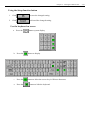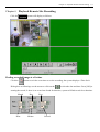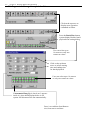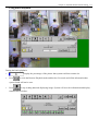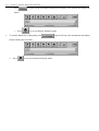
1
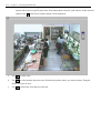
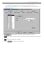
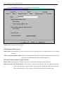
Receiver User Manual
Telexper International Incorporated © 1992-2008
VisionSoft Incorporated © 1992-2008
TABLE OF CONTENTS
Chapter 1 Introduction .................................................................................................................. 1-1
Overview of the Digital Picture Receiver.............................................................................................1-1
Chapter 2 Receiver Main menu................................................................................................ 2-1
Chapter 3 Dial and Connect ....................................................................................................... 3-1
Phone book setup..............................................................................................................................................3-1
Use the phone book .........................................................................................................................................3-5
Scheduled Dial ...................................................................................................................................................3-6
Chapter 4 System Setting ............................................................................................................. 4-1
Scheduled Dial setting ....................................................................................................................................4-1
Line setting ..........................................................................................................................................................4-2
Comport setting ................................................................................................................................................4-3
Other setting .......................................................................................................................................................4-4
Setting ISDN .......................................................................................................................................................4-5
Chapter 5 Viewing the Remote Site ....................................................................................... 5-1
Remote setting....................................................................................................................................................5-3
Setting camera properties......................................................................................................................................................... 5-3
Setting Alarm properties .......................................................................................................................................................... 5-7
Recording mode setting ........................................................................................................................................................... 5-9
Motion detection function...................................................................................................................................................... 5-10
4-zone motion detection setting ............................................................................................................................................. 5-12
Setting relay output properties (Optional : Depended on Transmitter site) ........................................................................... 5-13
Setting Backup system properties (Transmitter site with Tape) ............................................................................................ 5-14
Setting Backup system properties (Transmitter site with Hot Swap hard disk).................................................................... 5-15
Setting Transmission Connection properties ......................................................................................................................... 5-16
Sequencer function ................................................................................................................................................................ 5-17
Administration setting............................................................................................................................................................ 5-18
Camera Stable time ......................................................................................................................................................... 5-18
Change Password-Administrator ................................................................................................................................... 5-19
Change Password-System operator................................................................................................................................ 5-19
Change Password-operator............................................................................................................................................. 5-20
Change Password- Telephone-Connection .................................................................................................................... 5-20
Alarm Callback-Telephone ............................................................................................................................................. 5-21
Change Date/time............................................................................................................................................................. 5-22
Software Upgrade ............................................................................................................................................................ 5-22
Using the Setup function button .............................................................................................................5-23
Use the keyboard on screen .................................................................................................................................. 5-23
Chapter 6 Playback Remote Site Recording .................................................................... 6-1
Finding recorded image at a fix time .....................................................................................................6-1
Finding recorded image for a period of time .....................................................................................6-2
Using Batch Playback ....................................................................................................................................6-3
Printing image picture ...................................................................................................................................6-5
Chapter 7 Local Playback ............................................................................................................ 7-1
Chapter 8 Alarm ................................................................................................................................ 8-1
Chapter 9 Using the Receiver Step - by - Step ................................................................ 9-1
How to make Receiver work with your modem ...............................................................................9-8
Chapter 10 How to make Receiver work on Windows Vista 32 bits .............. 10-1
Chapter 1 Introduction
1-1
Chapter 1 Introduction
Overview of the Digital Picture Receiver
The Receiver is designed to receive freeze-frame video images over a standard telephone line from the
Transmitter . The Receiver can auto-answer the telephone from the transmitter.
The Receiver may be powered by a 110/220 VAC, 1 amp source with the switch selection between
110VAC and 220VAC.
The Receiver allows the user to select up to 16 video camera images (depend on your Transmitter site
model) from full, quad, up to 1/64 screen from a remote location. Each camera has a corresponding alarm
input that can be armed or disarmed remotely with the Receiver.
The Receiver begins displaying images when the telephone line is connected to the transmitter.
The Receiver can also be used to activate up to 16 relays (depend on the transmitter site model) on the
Transmitter site, to open doors or gates, or to turn on lights at camera locations.
The Relay Control Box must be used when this option is desired.
The Receiver offers a choice of three (3) level resolutions on the freeze-frame image that vary depending
on the transmission speed selected on the Receiver side.
At the Receiver site the images, site ID, the time and date, camera title, and the alarm and relay status can
easily be seen on the monitor screen.
Chapter 2 Receiver Main menu
2-1
Chapter 2 Receiver Main menu
Introduction System’s command button
1.
When the line signal is turned on. Press this button to login TransVisioner and to
see the living image captured.
2.
Press this button to pop up Telephone Dial Box.
3.
Press this button to enter the System Setting menu.
4.
Press this button to enter Local Recording Playback menu.
5.
Press this button to exit the Security System.
Chapter 3 Dial and Connect
3-1
Chapter 3 Dial and Connect
Click the
button to pop up the Telephone panel as following:
Phone book setup
System allow user to pre-enter 16 sets remote site name and telephone number use to connect remote
site.
a.
click on the down arrow at the right side of the
From
item box, or click (or press) the up/down arrow to select item from the list.
b.
Press the
button system display.
3-2
Chapter 3 Dial and Connect
c.
Press the
button to display.
d.
Press the
button to allow the user to key in Chinese characters.
e.
Press the
f.
button to hide the keyboard.
Enter the Remote Site Name (only 20 characters is allow)
Chapter 3 Dial and Connect
3-3
it will write to phone book and display as follow;
g. Press
h. To enter telephone number use the mouse to point to the Digit button, select the number you want
by clicking it with the mouse and use the following button to help you to set the telephone number.
Backspace button, allow user to correct the phone number.
i.
ii.
Click the
button to clear the telephone number on the LCD Display that is used for
dialling out.
iii.
Click the
button while entering the telephone number to instruct the system to pause
2 seconds in the dialling process. Multiple numbers of pausing times can be entered.
3-4
Chapter 3 Dial and Connect
iv.
The number you entered will display on the LCD panel.
to write into the phone book.
i.
Press
j.
To clear or rename a remote site name.
i.
Click (or press) the
up/down arrow to select the phone set.
Chapter 3 Dial and Connect
ii.
Delete or retype the data then press
3-5
.
k. To clear or change a remote site telephone number.
i.
Click (or press) the
up/down arrow to select the phone set.
ii.
System display telephone number on LCD panel.
iii.
Click the
button to clear the telephone number, use the Digit button to enter
telephone number then press
.
Use the phone book
1.
After preset remote name and telephone number is completed, select the remote site and telephone
number you want to dial.
2.
Use the mouse to click (or press) the up/down arrow to select
the telephone number from the list or click on the down arrow at the right side of the telephone box, and
then click on the number you want to dial.
3.
Click the
button to dial out the telephone number. When Telephone line is connected
will turn on. Select the
button to login the TransVisioner
System.
4.
If the
is check (a
appear), when the line is disconnect
because of poor communication quality, then the system will redial and reconnect automatically.
5.
Click the
button to hang up the telephone line.
6.
Click the
button to close the Telephone panel.
3-6
Chapter 3 Dial and Connect
Scheduled Dial
1.
Press (or click) the up/down arrow to select the start item and press the
Start button to dial from the start item to the last item (up to 20 items).
2.
Press to stop the scheduled
dialing processing.
During the schedule dialing
process press this button to
skip the current items and
got to next item.
The error diagram box indicate the schedule
3.
dial failure item.
Chapter 4 System Setting
4-1
Chapter 4 System Setting
Click the
button to display a system setting as follow:
Scheduled Dial setting
1.
Repeat Count:
Click (or press) on the up/down arrow to select the time interval for circling
the remote site , if the 0 is selected then the infinite is set
2.
Item:
3.
Item Property:
a.
Click (or press) on the up/down arrow to selected remote site from 1- 16.
Use the Enabled check box to turn on or turn off the scheduled dial function. When an
b
appears inside the box, the Scheduled dial is turned on.
b.
Task duration: Set the duration time that the current item selected will transmit.
c.
Dial: Click (or press) on the up/down arrow to set the dial time, redial pause, redial count.
d.
Camera: When an
b
appears inside the digital box indicate that the selected camera is turn on, select
up to 8 camera.
e.
Display: Use the mouse to click on the button to select the image displaying size.
f.
Layout: Use the mouse to click on the button to select the image displaying method.
4-2
Chapter 4 System Setting
Line setting
1.
Line Speed Select modem transmitting speed from auto, 2400 to 33600 BPS.
2.
Dialling Type: Depending on the telephone system in the area select either
TONE or PULSE.
3.
Modem Sound Turn on or turn off the modem sound during the dialling process.
4.
Line Type Select the normal telephone line
or dedicated line
operation.
5.
Check Dial Tone:
or
. If “yes” is checked then the system will check the dial
tone first before it dials out the telephone number.
Chapter 4 System Setting
Comport setting
Select the right comport according to your computer and Baudrate (Select 115200 for ISDN).
4-3
4-4
Chapter 4 System Setting
Other setting
This pass word is used for the Auto Login function. If the
1.
function is checked the Receiver will not ask for the user
password and will use the Auto Login Password to login the Transmitter.
If this box is checked, when the line is connected it
2.
will login automatically.
3.
If this box is checked, the Receiver recording function will be turned on.
: If this box is checked, the Control panel will be displayed
4.
when the system is logged in.
5.
6.
if this button is pressed , a Digit panel will appear on the screen to select the number.
Change the appropriate setting, and then click the
button. Click the
button to abort the changes and the system will not save the changed setting.
Chapter 4 System Setting
Setting ISDN
I.
Transmitter Site:
i.
Get into [Setup] screen.
ii.
Choose Connection tab.
iii.
Change Baudrate to 115200.
iv.
Change modem type to 10.
v.
Enter the Initial Command String according to your specific TA Adapter.
vi.
Click [OK] to save the setting.
II. Receiver Site:
1.
Press and hold the Ctrl key, and click the [Setting] button.
2.
Choose the Line tab from [Setup].
3.
Change modem type to 10.
4.
Enter the Initial Command String according to your specific TA Adapter.
5.
Click [OK]button to save the setting.
6.
Choose Comport tab from[Setup].
7.
Change Baudrate to 115200.
8.
Click[OK] to save the setting.
III. ISDN TA(Teminal Adapter):
For E-TECH
Protocal V.120
Use the &F2%A2=2S0=2 as the Initial Command String
Protocal V.110
Use the &F1S0=2 as the Initial Command String
57600 bps (TAIWAN) 38400 bps (JAPAN)
For ZyXEL
Protocal V.120
Use the &FB20S0=2 as the Initial Command String
Protocal V.110
Use the &FB18S0=2 as the Initial Command String
38400 bps (JAPAN)
For TAICOM
Protocal V.120
Protocal V.110
Use the &F%A2=2S0=2 as the Initial Command String
Use the &F%A2=1S0=2 as the Initial Command String
NOTE: The Command Set varies from different type of TA manufacture, please refer to their
user manual.
4-5
Chapter 5 Viewing the Remote Site
5-1
Chapter 5 Viewing the Remote Site
When the telephone line is connected the
light will turn on; click the
button; a password Dialog Box will appear as follows (If Auto login is checked the
system will automatically login without asking user to enter the password):
Enter the password, the system will display the living capture on the screen.
5-2
1.
Chapter 5 Viewing the Remote Site
Camera: User can select up to 8 or 16 cameras (Depend on the Transmitter model) to view on the screen
by clicking the camera digit button
2.
.
Display: Use the mouse to click on the button below to select the image displaying size
.
3.
4.
Use the mouse to click on the button below to select the image displaying method.
a.
Sequential split screen.
b.
Display in the middle of screen.
Split screen fixed position respectively.
c.
Speed: Choose the transmitting speed of the TransVisioner from 1 to 3.
The higher the speed number chose the higher speed of the transmitting; however this usually
produces a poorer quality picture. In normal cases, it is best to choose Speed 2.
5.
6.
Minimize the video control panel.
Click
7.
Hide the video control panel.
8.
9.
button to record all the display pictures on receiver side.
Exit the video control menu and return to upper menu.
Click the
10. Click the
button and the system will pause the monitoring process.
button and the system will allow viewing the recorded pictures that are at
Transmitter site.
11. When you click the
button, the system will pop up a remote control sub menu that can control
up to 16 relay contacts (Depend on the Transmitter model).
Chapter 5 Viewing the Remote Site
5-3
Remote setting
Click the
button to enter the Remote Setting panel:
Setting camera properties
Select the Camera tab. The system displays the following:
Host name: This is the name of the unit.
Speed: This is the Recording speed of the unit, listed in frames per second (fps). This speed is reflected on the
main status display screen. The frames per second on this unit is divided by the number of active
cameras.
For example, if a unit is running at 20 frames per second and there are five active cameras, there will be
4 frames for each camera captured per second.
: With this setting, each active camera on this unit will record at a
speed independent of the other cameras. If this entry is selected under the speed box, an additional box
will appear for each individual camera that will allow the user to
customize the speed for that camera.
5-4
Chapter 5 Viewing the Remote Site
Name:
This is the name of the camera or location for display on the monitor.
Scheduled:
This field indicates continuous recording time for the camera. The default is 00:00-24:00 which
indicates a 24 hour period recording time.
To change the continuous recording time for a particular camera, change the entry. For example, to
record from 2pm to 4pm, type: “14:00-16:00”.
To list more than one recording time, insert a comma (,) to indicate breaks in recording time. For
example, to record from 10am to 2pm and from 4pm to 10pm on a camera, type:
“10:00-14:00,16:00-22:00”.
To record times that would go past midnight (24:00), break the scheduled recording time into two
parts. For example to record from 10pm to 6am, type: “22:00-24:00,00:00-06:00”.
If you leave the Scheduled Recording Time entry blank for a camera, the camera will only record if it
is set up to record by trigger through alarm or motion detection. If camera inputs will not be used, erase
the scheduled recording times from the unused cameras to ensure that it will not record anything into
the unit and take up hard drive space with blank recording from unused camera inputs.
Chapter 5 Viewing the Remote Site
5-5
Weekday:
Use this field if you want a camera to record on certain days of the week.
Enter: 1 = Monday
2 = Tuesday
3 = Wednesday
4 = Thursday
5 = Friday
6 = Saturday
0 = Sunday
For example, if you want a camera to record on Mondays, Wednesdays and Fridays, type in the field:
“1,3,5”. Separate the days by using commas.
If this field is left blank, then the camera records for all days according to the schedule in the
Scheduled Recording Time field.
Note: The weekday setting for cameras cannot, for example, record events on Monday from
10 am
to 2 pm and then on Tuesday from 1pm to 4 pm. The weekday settings will use the same
scheduled recording time of all the days indicated in this field.
Mode:
This selects the type of compression for the camera:
Normal mode (Wavelet compression): Normal mode produces better image quality but reduces the
storage time. If the camera uses the Pan/Tilt/Zoom feature, then Normal mode must be used.
Enhance mode (Modified JPEG compression): Enhanced mode uses Telexper’s proprietary
compression and can store 2 to 3 times as much as the Normal mode.
Quality:
Select the image quality from Low, Fair, Good, Better, or Best. More space on the hard drive is used
with higher quality images.
5-6
Chapter 5 Viewing the Remote Site
Hidden:
Select this to hide the individual camera from the live screen. If a camera is hidden, that means that the
camera will not show up on the live screen display and the button for the camera on the live screen
toolbar will be grayed out, indicating that the camera cannot be activated. This will not affect the
recording of the camera into the hard drive.
Video Loss Detection:
When the Video Loss Detection is active, the system will automatically detect cameras that are not
properly connected to the unit. If video signal loss is detected, the corresponding camera digital light
will turn red.
If the Scheduled Recording Time field contains a time, then the unit assumes that the camera position
should have a camera attached to the input and will likewise appear as red under Video Loss Detection.
On this
chosen.
panel, adjust the color, brightness, and contrast of a specific camera
Chapter 5 Viewing the Remote Site
5-7
Setting Alarm properties
Select the Alarm tab and the System displays the following:
1.
Select an alarm:
Click on the list to select from Alarm1 to Alarm 16 (for 16 channel model), or Alarm1 to Alarm 8
(for 8 channel model).
5-8
2.
Chapter 5 Viewing the Remote Site
Setting individual Alarm Properties
a.
: Click on this button to enable (green light) or disable the alarm function.
(Normal Open ) or
b. Select Alarm type:
( Normal Close).
c. Name: Default is Alarm1 to Alarm 16. The characters in the Name column for the Alarm chosen can
be changed by keyboard.
d. Type: Select between Pulsed Input or Latched Input.
Pulsed Input: The recording time depends on the Recording Time specified in this setup menu.
Latched Input: The recording time depends on the alarm sensor ON/OFF. If user does not
acknowledge the alarm, the system will return to normal recording speed as soon
as the Recording Time expires.
e. Recording Camera: Select the recording camera corresponding to the alarm. Usually Alarm 1
corresponds to Camera 1, Alarm 2 corresponds to Camera 2, etc.
f. Press the
button to turn ON (Green light) or turn OFF the View Live function. If
this function is ON, while an alarm occurs, the system will switch to the Live Mode immediately.
The user has turned on
For example:
Camera 1 View Live function; when Camera 1 alarm occurs, the user will see camera 1’s live image
displayed on the monitor immediately.
g.
Recording time
seconds: Use the mouse to click on the up / down arrow to select
the recording time after alarm is activated.
h.
button to turn ON/OFF alarm buzzer; then select alarm buzzer time
Press the
Seconds.
i.
Press the
button to cancel the setting and use the system default value.
Chapter 5 Viewing the Remote Site
Recording mode setting
: User may select an
alarm recording mode:
a. Record last incident's camera only: Record only the last-alarmed camera.
b. Record incident's camera only: Record all the alarmed cameras.
c. Lasts incident's camera higher priority: Speeds up the recording speeds of the last- alarmed
camera; Other cameras will still record but at a lower recording rate.
Incident's cameras higher priority: Speeds up the recording speed for all the alarm cameras.
Other cameras will still record but at a lower recording rate.
5-9
5-10
Chapter 5 Viewing the Remote Site
Motion detection function
Select the Motion Detection tab, system displays as follows:
1. Detect: Press the
to turn ON or turn OFF motion detection.
2. After turning ON the motion detection, user can select the following setting.
a. Sensitivity: The higher the value the higher the sensitivity of the motion detection.
b. Sound: Click on
c. Frame: If
to turn ON (LED turns green) the alert sound when an activity occurs.
is turned on (LED turns green), a red outline box will appear on the corresponding
picture when system detects activities.
d. Record: Click on
to double the recording speed.
e. Alarm: Click on
to turn ON (LED turns green) the alarm function. When the alarm function
is ON and the corresponding camera activity occurs, it will handle it as a normal alarm and will register to
the history event log.
f.
Schedule:
schedule display.
Chapter 5 Viewing the Remote Site
g. To change the schedule press
and the system displays the following,
Enter a new schedule here, and press Refresh to accept
the changed schedule. Schedules are separated by “,”.
5-11
5-12
Chapter 5 Viewing the Remote Site
4-zone motion detection setting
System allows user to specify up to four-zone motion detect area for each camera. At the selected
camera click
a full screen camera image will be displayed.
a.
Use
to select zone.
b.
Use
to select motion detection zone. Position the pointer where you want to detect. Drag the
mouse to resize an area.
c.
Use
to cancel the zone that you selected.
Chapter 5 Viewing the Remote Site
5-13
Setting relay output properties (Optional : Depended on Transmitter site)
It is an optional function user need to buy at lease one piece of ADAM-4520 (RS-232 to
RS-422/RS-485 CONVERTER) and one piece of ADAM-4050 Relay Box (one relay box could
control 8 relay output).
Click this button to enable (green light) or disable the relay function.
a.
b.
Name: Default is Relay 1 to Relay 8. The name in the Name column for the Relay chosen may be typed
in.
c.
Type: Select between Momentary or Latching.
d.
Press the
to set back to system default value.
5-14
Chapter 5 Viewing the Remote Site
Setting Backup system properties (Transmitter site with Tape)
Select the Backup system tab; System displays the following:
Name: Insert the name of the tape here.
While Backup Medium is full…
Buzz Enable: Selecting this will cause the buzzer to sound when the tape is full and alerts the user to change
the tape.
Auto recycle if hard disk is full: If this is checked and the hard drive and tape are both full, the system will
erase the tape and backup the data from the beginning.
When the Backup Medium is going to format…
Buzz Enable: Selecting this will cause the buzzer to sound when the tape will be formatted.
Data Protection: On Tape Password: This will place a password on the tape. The new password will take
effect on the next tape inserted into the system and the current tape will not be affected.
Once the password is set, the system will ask for the password to read the tape.
Chapter 5 Viewing the Remote Site
5-15
Setting Backup system properties (Transmitter site with Hot Swap hard disk)
Select the Backup system tab; System displays the following:
Name: Insert the name of the Hot Swap Hard Disk here.
Backup Mode
Cyclic Backup: If this is checked and the Hot Swap Hard Disk is full, the system will backup and overwrite
the data from the beginning.
While Backup Medium is full….
Alert:
Selecting this will cause the buzzer to sound when the Hot Swap Hard Disk is full and alerts
the user to change Hot Swap Hard Disk.
Auto recycle: If this is checked and the built in Hard Drive and Hot Swap Hard Disk are both full, the system
will backup and overwrite the data from the beginning.
When the Backup Medium is going to format…
Alert: Selecting this will cause the buzzer to sound when the Hot Swap Hard Disk will be formatted.
Chapter 5 Viewing the Remote Site
5-16
Setting Transmission Connection properties
Select the Connection tab; System displays the following:
1.
Comport : Select modem connection port.
2.
Baudrate: Select modem speed.
3.
Dial: Depending on the dialing system in the area, select either TONE or PULSE.
4.
Modem Sound: Turn ON or turn OFF the modem sound during the dialing process.
5.
Line Type: Select the PSTN line (
6.
Check Dial Tone:
or
) or dedicated line (
) connection.
. When ON is selected, the system will check dial tone before
dialing.
7.
Modem Type: Depends on the modem you use. If system cannot auto detect the value, set it to 0.
8.
Number of rings to answer: Set the number of phone rings before system answers the phone and connect
it.
9.
Period of line-checking: Set the time interval for the system to check the modem status.
Chapter 5 Viewing the Remote Site
5-17
Sequencer function
User can connect a CCTV monitor to VS-168 (VOUT connector), and do the following setup to
process the sequencer function.
1.
Selected desired camera from cameras list by clicking the cameras desired.
2.
Set the dwell time between each camera.
3.
Press
4.
Follow Alarm Cameras – When alarm occurs, the image will be shown immediately on screen.
5.
Follow Motion Cameras – When motion is detected, the image will be shown immediately on screen.
to turn ON or OFF the sequencer function.
5-18
Chapter 5 Viewing the Remote Site
Administration setting
Select the Admin tab; System displays the following:
Camera Stable time
This means the stable time between each camera switching.
Default
=10 means the stable time is
20msX10 =200ms for PAL system
16.6msX10=166ms for NTSC system
If you encounter picture rolling problem, you can increase the number to solve it.
Warning: Do not select more than 18, otherwise the DVR recording speed will decrease dramatically.
Chapter 5 Viewing the Remote Site
5-19
Change Password-Administrator
To change the Administrator password, from job list Select 1. Change password-Administrator and
press
; System displays a dialog box on the screen.
Enter the old password, new password and verify new password then press
to accept the
new password; System will use the new password to access the system in the future.
Change Password-System operator
The Administrator could assign and change the password for the system operator. From Job list Select 2.
Change password-System operator and click on
, system will display a dialog box on
the screen.
Enter the old password (Enter either Administrator password or System operator old password), new
password and verify new password again, then click
will use the new password to operate the system afterwards.
to accept the new password; System
5-20
Chapter 5 Viewing the Remote Site
Change Password-operator
The Administrator could assign and change the password for the operator. From Job list Select
3. Change password-operator and click on
, system will display a dialog box on the
screen.
Enter the old password (Enter either Administrator password, System Operator password or Operator old
password), new password and verify new password then click
to accept the new password.
Change Password- Telephone-Connection
The Administrator could assign the password for the telephone connection. From Job list Select
4.Change Password- Telephone-Connection and click on
, system will display a
dialog box on the screen.
Enter the old password (Enter either Administrator password or old telephone password), new password
and verify new password then click
to accept the new password; System will check for the
new password before accepting the telephone connection.
Chapter 5 Viewing the Remote Site
5-21
Alarm Callback-Telephone
The Administrator could assign the Alarm Callback-Telephone information. From Job list Select 5.Alarm
, system will display a dialog box on screen.
Callback-Telephone and click the
i.
ii.
Call back telephone Item from 1 to 4.
Enter the call back telephone number into
, and select telephone type
.
iii.
The Dial Time specifies how many seconds that the Transmitter will
wait for the Receiver to respond. .
iv.
The Redial Pause specifies how many second the Transmitter will
redial after the Receiver fails to respond.
v.
The Redial Count specifies the number of telephone calls that the
Transmitter will retry when the call is not completed. If the call is still not complete, the transmitter
will use the next telephone number in memory using the same procedure.
5-22
Chapter 5 Viewing the Remote Site
Change Date/time
To correct the system time, from Job list select 6. Change Date / Time and click
; System
displays the Set Date / Time panel.
Software Upgrade
To upgrade new software, from job list select 7. Software Upgrade and click
displays a confirmation message as follows.
Click OK, system displays the following confirmation message:
; system
Chapter 5 Viewing the Remote Site
Using the Setup function button
1.
Click
to store the changed setting.
2.
Click
to discard the changed setting.
Use the keyboard on screen
a.
Press the
button system display
b.
Press the
button to display
c.
Press the
button to allow the user to key in Chinese characters.
d.
Press the
button to hide the keyboard.
5-23
Chapter 6 Playback Remote Site Recording
6-1
Chapter 6 Playback Remote Site Recording
Click the
system will display as follows:
Finding recorded image at a fix time
Click the
button to seek the exact time to see the recording; the system displays a Time Seek
Dialog box as following: use the mouse to click on the
to select the date and time. Press [OK] to
starting the search, if there is no record was found for that time, system will find record close that time.
Month
Hour
Day
Minute
Year
Second
6-2
Chapter 6 Playback Remote Site Recording
Finding recorded image for a period of time
Click on the up arrow to
display more operation
command as follow.
Press the Batch Play button,
system display Remote batch
playback time setting dialog.
User can select up to
16 camera or only one
camera at a time.
Click on the up/down
arrow to select starting
time and ending time
for batch playback.
User can select up to 16 camera
or only one camera at a time.
If Automatic Hang Up is check (an √ appears
inside it), when batch playback time is out
system will disconnect the line automatically.
Press it to read data from Remote
site, from start to end time.
Chapter 6 Playback Remote Site Recording
6-3
Using Batch Playback
During the batch playback:
Display the percentage of the picture that system read from remote site.
1.
2.
Press
to exits the Remote Playback mode and back to live mode and all the information that
system found will not be save.
3.
Press
to stop reading data and displaying image. System will save the information and display
function box as follow.
Chapter 6 Playback Remote Site Recording
6-4
a.
Press
to replay all the information that has been display. The function box display as
follow.
i.
4.
Press
to revert to Remote Playback mode.
To end the Batch Play reading data press
function dialog box as follow.
a.
Press
to revert to Remote Playback mode.
. System will save the information and display
Chapter 6 Playback Remote Site Recording
6-5
Printing image picture
While viewing the tape, the viewing process can be stopped by clicking on the
button. Click the
button. A print dialog box appears and the picture will be displayed on the screen; user can then
choose to print the picture on printer or print to a file.
If user choose to print the picture on the file, a black dot appears inside it, then click the OK button. A
Save As dialog box displays:
The file location and file types for the file must be specified. It is recommended to print the
image on the 1.44M floppy and save File as Type:
.BMP - 1 image frame per 1.44M floppy; can be from Paint Brush.
.JPG - 30 image frames per 1.44M floppy.
.TIF- 1 image frame per 1.44M floppy; can be read from most commercial paint software
package.
Chapter 7 Local Playback
7-1
Chapter 7 Local Playback
In the TransVisioner menu choose the
button; the receiver side’s recording data
(only one recorded tape) can be seen.
1. Move the mouse over the scrolling bar and select the starting point (it displays by the date and time
reference).
2.
Click the
button to play the recording data.
3.
Click the
button to revert the recorded data.
4.
Click the
button to stop the playing function.
5. Click the
button to see the next picture.
6.
Click the
button to see the previous picture.
7.
Click the
button to stop current display tape and exit playback function.
7-2
Chapter 7 Local Playback
8. Click the
9. Click the
button; a dialog box will appear asking for confirmation of the clearance.
button to seek the exact time to see the recording; the system displays a Time Seek
dialog box as follows: Use the mouse to click on the
Month
Hour
Day
Minute
to select date and time:
Year
Second
10. While viewing the tape, the viewing process can be stopped by clicking on the
Click the
button.
button. A print dialog box appears and the picture will be displayed on the
screen; user can then choose to print the picture on printer or print to a file. . In the following figure,
one image has been selected for display on the screen and the image has been printed on
printer.(When select print on printer make sure the printer has connect to the VS3000
Properly)
Chapter 8 Alarm
8-1
Chapter 8 Alarm
Upon an alarm contact open: if the Transmitter and the Receiver are already connected, the Transmitter
will send the image to Receiver site immediately. Otherwise the Transmitter will use the four set
emergency phone numbers in its memory with the maximum retries specified in the Telephone Redial
Count.
1.
Click the
to release the alarm; the system will constantly send the alarm message until the
alarm is connected.
2.
Click the
button to turn ON/OFF the alarm sound. When the light turns green (
indicates alarm sound is on.
3.
When you click the
button, the system will pop up a remote control sub menu that can
control up to 16 relay contacts (Depend on the Transmitter model).
)
Chapter 9 Using the Receiver Step – by - Step 9-1
Chapter 9 Using the Receiver Step - by - Step
When entering the TransVisoner system, the system displays the TransVisioner main menu.
Following are instructions for use of the TransVisioner:
1. From the main menu choose the Setting button, It displays a System Setting dialog box.
2.
From the System Setting dialog box select the Scheduled Dial Tab.
9-2
Chapter 9 Using the Receiver Step – by - Step
3. Select the appropriate information as shown in following Figure.
4.
From the System Setting dialog box select the Line Tab.
Chapter 9 Using the Receiver Step – by - Step 9-3
5.
Select the appropriate information as shown in following Figure.
System indicates the default Modem rate
Select the type of telephone system’s dilation,
Default is tone.
Turn ON(Yes) or OFF(No)
When two lines try to connect, if the
Modem Sound is turned off, there is no
modem sound.
Choose the type telephone line used for transmittal.
9-4
Chapter 9 Using the Receiver Step – by - Step
6.
From the System Setting dialog box select the Comport Tab.
7.
Select the appropriate information as shown in following Figure.
Chapter 9 Using the Receiver Step – by - Step 9-5
8.
From the System Setting dialog box, select the Other Tab.
Use the Digit panel to Enter the Auto Login Password
press this button:
The system displays a Digit Panel
When the Automatic input Login password is checked, system automatically initials
the password.
When the Automatic Login while Line Connect is checked, system will automatically,
Login while the line is connected.
When the Record is checked, system will record all the image data system has captured.
When the Show Control Panel on Login is checked, system shows the Control Panel
every time the VS3000 system is entered.
9-6
Chapter 9 Using the Receiver Step – by - Step
9.
After Setup is done, if Lease line is user’s choice then go to STEP 10. Otherwise choose the Dial
button; use the Digit Panel to enter the Remote site telephone number,
Press Dial button to connect the line.
Enter
remote site
name.
Phone book:
Remote site
telephone
number and
name.
To instruct the system to pause 2 seconds on the
Dialing process, multiple numbers of pausing times can be
entered.
Chapter 9 Using the Receiver Step – by - Step 9-7
10. After line is connected
(light turns on), choose the View button; An Input
Remote Password dialog box displays:
If the password entered is correct , the remote site can be seen; Then follow all
operations described in Chapter 5 Viewing the Remote Site .
9-8
Chapter 9 Using the Receiver Step – by - Step
How to make Receiver work with your modem
1. Make sure where your modem located in your computer.
Select the right COM port address.
In the TXPH program
1.1
Press the control button in your keyboard and click the “SETTING” button to enter System
Setting submenu.
1.2
Click the “COMPORT” selection.
1.3
Select the right COMPORT between COM1 and COM8.
2. Select the “LINE” selection
2.1
The manufacture default setting for Modem type is “0” which will work for most the modem,
which is implemented with Rockwell chip.
2.2
If your modem is US Robotic or 3 Com then you need to select type “10” and type in “AT&F1”
in the Initial Ex Box.
Chapter 10 How to make Receiver work on Windows Vista 32 bits
10-1
Chapter 10 How to make Receiver work on Windows Vista 32 bits
1. Move mouse cursor to the shortcut of program, then right click mouse button, and click “Properties”.
2. Select “Shortcut” Tab in the Properties, then click “Advanced”.
3. In the “Advanced Properties” display box, check “Run As Administrator”, then click Ok. Click Ok
again to quit and save Shortcut Properties.
You can run Receiver Software on Windows Vista 32 now.