1
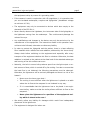
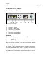
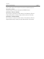
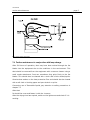
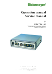
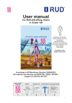
User Manual
XE 5600-CCD
endoscopy video camera
with integrated 100W xenon lightsource
Endoscopy Support Services, Inc.
3 Fallsview Lane
Brewster, NY 10509
914-277-1700 • 914-277-7300 Fax
E-mail: [email protected] • URL: http://www.endosocpy.com
user manual
table of contents
page 1
1 HINTS ON USING THIS MANUAL _____________________________________________________2
2 DESCRIPTION OF THE EQUIPMENT __________________________________________________3
3 GENERAL HINTS / SIGNS AND SYMBOLS _____________________________________________4
3.1 extent of delivery
4
3.2 explanation of symbols
4
3.3 safety
4
4 POSITION OF CONTROL ELEMENTS__________________________________________________6
4.1 control elements on the front panel
6
4.2 connectors on the rear panel
9
5 CONNECTING THE EQUIPMENT ____________________________________________________11
6 OPERATING THE EQUIPMENT ______________________________________________________13
6.1 preparing for operation
13
7 SERVICE AND MAINTENANCE ______________________________________________________14
7.1 cleansing and disinfecting
14
7.2 Exchanging the main fuses
14
7.3 Exchanging the lamp
15
7.4 Further maintenance in conjunction with lamp change
17
8 TECHNICAL DATA ________________________________________________________________18
9 SPARE PARTS ___________________________________________________________________19
10 GENERAL HINTS ________________________________________________________________20
11 TABLE “TECHNICAL SERVICE-INFORMATION” ______________________________________22
The typed label (see rear of unit) contains
type: ____________________________
technical data, type, and serial number of
s/n : ____________________________
your unit. Please always indicate this data
date: ____________________________
when ordering spare parts or in case of any
class: ___________________________
questions.
volt: ____________________________
Please enter here the technical data of
your device!Î
File: xe5600.doc, last update: 10. September 1998
amp: ____________________________
user manual
hints on using this manual
1
page 2
HINTS ON USING THIS MANUAL
This Operation Manual is designed to help you understand the function and the operation of
your equipment.
Before you switch the equipment on for the first time, please read thoroughly this manual
and pay special attention to all safety instructions, so that endangering for the user and the
patient is precluded.
Please always store this manual with the equipment.
Please pay attention to those sections, which are emphasized by the following signs:
Attention ,important note !
Safety note !
Service
All rights on this operation manual, especially the rights of duplication and publication and
the rights on translation are reserved. No part of this operation manual may be reproduced
by any means (by photostatic copy, microfilm or other methods) without preceding written
consent of Endoscopy Support Services, Inc. or be reproduced, multiplied or published by
means of electronic data processing.
The information given in this operation manual can be changed or extended without notice
and do not represent any liability.
Errors and technical changes excepted.
© Endoscopy Support Services, Inc., April 1998
user manual
description of the equipment
2
DESCRIPTION OF THE EQUIPMENT
The equipment you have purchased features a state-of-the-art color CCD camera
which was especially designed for use with endoscopic applications. In combination with the built-in high-intensity xenon illumination, the device offers the user a
compact unit for optimal image quality in nearly every endoscopic discipline.
CCD camera
Full digital signal processing ensures true color reproduction. The camera consists
of a control unit and a complete watertight camera head.
Located at the front of the ergonomically shaped camera head, there is a CMount-Thread adaptation, where you can connect usual lenses, vario-focus TVcouplers or other couplers to connect the endoscope.
Located inside the camera head is the CCD-chip, which takes the image and converts it into electric signals. These signals are conducted through the camera cable
to the control unit.
Inside the control unit, the image data is processed and is provided either as
Standard-FBAS-Signal (BNC-connector, VHS-standard) or as Hosiden-Signal (Y/Csignal, Mini-DIN-connector, S-VHS-standard) on the rear panel for displaying on
the monitor and/or other devices, such as videoprinter, videorecorder, etc.).
The image-brightness is controlled by an electronic shutter, which is working with
a shutter-cycle at minimum of 1/2.000.000 sec., so that even when the image is
totally irradiated a well-balanced video picture is delivered to the monitor.
If the image is extremely dark illuminated, the shutter cycle becomes so high,
that it is impossible to display a flicker-free picture. In this case, the videosignal is
emphasized electronically by max. +30dB.
This electronic emphasis is called AGC (Automatic Gain Control). It has to be
taken into account that the noise on the picture is increased when the AGC is
working.
xenon lightsource
The built-in xenon illumination features a high-intensity xenon lamp, which is installed in a reflector. The lamp designed is optimized for endoscopic applications.
The color temperature equals daylight quality with a color temperature of 5.700 K.
page 3
user manual
general hints / signs and symbols
3
GENERAL HINTS / SIGNS AND SYMBOLS
3.1 extent of delivery
Please verify immediately after having unpacked the equipment whether the
delivery is complete. The standard extent of delivery includes of the following:
• control unit
• camera head with cable and plug
• power supply cord
• user manual
• video cable Y/C (S-VHS)
3.2 explanation of symbols
please read accompanying documents
type BF equipment
Attention, hazardous voltage
Alternate electrical ground connector conductor
~
alternating voltage
3.3 safety
• Always connect all wires before switching on the equipment. Therefore refer to
chapter 5.
• The main plug may only be connected to a protectively earthed wall socket.
• The equipment must not be used in areas where there are dangerous flammable gases.
• The control unit is equipped with a fitting according to DIN 42801 for the connection of a potential equalization conductor. When running the equipment in
rooms which comply to class 1 or 2E according to MedGV, the control unit
must be joined to the central potential equalization of the operating room or of
page 4
user manual
general hints / signs and symbols
page 5
the equipment trolley by means of a grounding cable.
• If the camera is used in conjunction with HF-coagulators, it is imperative that
you use insulated endoscopes, couplers and lightguides. (breakdown voltage
at minimum 4.5 kV).
• The equipment may only be connected to devices which also comply to the
demands of the IEC 601-1.
• Never directly observe the lightbeam, the instrument side of the lightguide, or
the lightbeam coming from the endoscope.
This could severely damage the
retina of the eye.
• Any modifications and changes to the device may only be carried out by the
manufacturer of the equipment. The instructions made in this operation manual have to be followed, otherwise we refuse any liability.
• In order to protect the lightguide and the patient, there is a heat reflecting
filter installed which reflects the heat radiation produced by the Xenon-lamp.
Always check before switching on the equipment and especially after every
transport of the equipment whether this filter is unbroken. Otherwise, the heat
radiation is emitted to the patient at the distal end of the attached endoscope
and burning of the skin surface can occur.
• Naturally, the built-in xenon bulb produces apart from the light output a certain amount of heat, which is carried off by fan cooling. In order to ensure that
the heat flow is not hindered, the following precautions must be observed.
Otherwise, the lightsource will be seriously damaged and there is a risk of fire
hazard !
• Never cover the louver type slots !
• The cooling is most efficient when the lightsource is placed on a table
where the air flow at the rearpanel is not hindered in any way.
• If it is unavoidable that the lightsource has to be placed in an equipment trolley, make sure that the trolley allows sufficient air flow at the
rearpanel.
• Never place the lightsource in a partition of the equipment trolley which is closed at the rear !
• We strictly refuse any liability for damages which result from inadequately
placement of the lightsource.
• The equipment is designed for indoor use.
user manual
position of control elements
4
POSITION OF CONTROL ELEMENTS
4.1 control elements on the front panel
fig. 1: control elements on the frontpanel
c
d
e
f
g
h
i
main switch
connector for lightguide
connector for camera head
push-button “WHITEBALANCE”
push-button “WINDOW”
push-button “increase intensity”
push-button “decrease intensity”
main switch
The control unit is turned on by switching the main switch c.
The main switch has two different switching positions:
I
switched on
O
switched off
When the control unit is switched on, the green light illuminates inside the
switch.
connector for lightguide
This connector is used to connect and adjust the lightguide to the lightsource.
There is an interchangeable adapter screwed in. The adapter used has to match
the lightguide fitting you are using. Several adapters for all types of lightguides
are available. Most of these adapters have an automatic snap-in for the lightguide.
page 6
user manual
position of control elements
connector for camera cable
This connector is used for attachment of the plug of the camera cable.
The plug can only be plugged in a certain position. This is achieved by a
small nose on the top of the plug.
The red mark on the 14-pin-plug must correspond with the red mark on the
socket to install the plug.
The plug fastens automatically when completely plugged in.
To unfasten the plug; grip the knurled part of the plug and pull the plug out of
the socket.
push-button “WHITEBALANCE”
The WHITEBALANCE is done by pressing the corresponding push button f.
Therefore, aim the camera head on a homogeneously illuminated white sheet
of paper or a well-illuminated multi-color object. Simultaneously, press the
push button once. The button then will flash until the WHITEBALANCE is finished. The current WHITEBALANCE is stored in memory and is also saved,
when the camera is switched off.
Take notice, that the paper-sheet or the multi-color object is not irradiated,
that means, e.g. that the grain-structure of the paper is visible on the monitor.
If WHITEBALANCE is done correctly, a natural color reproduction is guaranteed.
push-button “WINDOW”
The WINDOW-function is turned on and off by pressing the corresponding
push button g.
The WINDOW-function carries out a light measurement that only affects a
central window of the picture. That means, that in contrast to standard
measurement, where the average brightness is integrated over the entire
picture size, only a center part of the image is taken to evaluate the average
brightness, outer margins are disregarded.
To activate the WINDOW-function, push the corresponding button. If the
WINDOW-function is activated, a yellow light inside the push button is illuminated and a light-gray rectangle appears on the monitor for a short time.
That represents the area that is taken for brightness evaluation.
If the object to be regarded is in the center of the picture, you should activate the WINDOW-function. The object itself is displayed correctly illuminated
page 7
user manual
position of control elements
on the monitor and the outer margins of the screen are displayed proportionately darker or brighter.
Anewed pressing of the button deactivates the WINDOW-function.
push-button “decrease intensity”
Use this button to decrease the output intensity of the lightsource. When the
lowest possible setting is reached, the light inside the button will illuminate.
push-button “increase intensity”
Use this button to increase the output intensity of the lightsource. When the
highest possible setting is reached, the light inside the button will illuminate.
page 8
user manual
position of control elements
4.2 connectors on the rear panel
fig. 2: connectors on the rear panel
8
9
10
11
12
video output terminal / S-VHS
video output terminal / VBS
Alternate electrical ground connector
main terminal device
main fuses / voltage selector
video output terminals
You can attach external output-devices such as monitor, videorecorder or
videoprinter to the VIDEO-OUT connectors.
The videosignal is provided in two different standards.
1. The BNC-terminal k provides the videosignal as VBAS-signal (compostsignal, VHS-standard).
2. The 4-pin-Y/C-terminal j provides the videosignal as Hosiden-signal
(separate conductors for chroma- and luminance-signal, S-VHS-standard).
Both video outputs are available simultaneously so that both standards can
be used at one time.
It is preferred to use the Y/C-signal than VBS-signal if possible. You will
achieve a much better image quality in contrast to VHS-standard.
Alternate electrical ground connector
The control unit is protectively earthed by the 3-pin power supply cord when
it is connected to a grounded wall socket, as prescribed.
When running the equipment in rooms which comply to class 1 or 2E accord-
page 9
user manual
position of control elements
ing to MedGV, the control unit must be joined to the central potential equalization of the operating theater or of the equipment trolley by means of a
grounding cable.
main terminal device
The plug of the power supply cord is connected to the main terminal device (11).
main fuses / voltage selector
This little drawer (12) right above the main terminal device contains the main
fuses. The window inside the drawer shows the currently selected main voltage. You have to control whether your main voltage corresponds with the
selection shown in the window. If you need to change the main voltage,
please refer to chapter 7.2.
page 10
user manual
connecting the equipment
5
CONNECTING THE EQUIPMENT
ALWAYS INSTALL ALL CONNECTIONS
BEFORE SWITCHING ON THE EQUIPMENT !
CONNECT THE POWER SUPPLY CORD !
Use the delivered protectively grounded power supply cord to connect the
control unit to a grounded wall socket. Please check whether the current voltage selection matches your local voltage.
CONNECT THE CAMERA CABLE !
Install the plug of the camera cable in the corresponding socket on the frontpanel as described above.
You can connect all lenses and endoscope couplers to the camera head,
which are equipped with a C-Mount-Thread or CS-Mount-Thread. When you
use objectives with CS-Mount-Thread, an additional intermediate ring is
necessary.
Your dealer supplies various lenses and couplers for your special requirements.
CONNECT THE EXTERNAL OUTPUT DEVICES !
As described before, there are several standards of videosignals available on
the rearpanel.
Here you can connect external output devices such as monitor, videorecorder, videoprinter, etc.
If you are using standard VBS-signal (BNC-terminal), please always apply
high-quality 75Ω-coaxial cables.
If the external output device has a switchable 75Ω-termination resistor, you
should switch this on.
If you connect several devices in a row, only the last device in the line needs
to be terminated by the termination resistor.
If the external device does not provide such a termination resistor, you
should connect the coaxial cable via a T-connection-adapter. The open end of
the T-connection adapter is then terminated with the 75Ω-resistor.
We recommend the use of the delivered S-VHS-cable.
page 11
user manual
connecting the equipment
CONNECT THE ALTERNATE GROUND CONNECTOR !
Join the Alternate Electrical Ground Connector on the rearpanel with a central
grounding point in the operating theater or to the equipment trolley.
CONNECT THE LIGHTCABLE
Connect the lightguide to the lightsource using a suitable adapter.
page 12
user manual
operation of the equipment
6
OPERATING THE EQUIPMENT
6.1 preparing for operation
After having installed all connections, the camera can be set to work.
Switch on the control unit using the main switch on the frontpanel c.
The green lamp inside the switch lights up.
If all other devices are switched on, a picture appears on the monitor.
The lamp ignites after 5 sec. and will reach it’s full intensity within a few seconds. Set a median intensity of illumination using the corresponding push
button h and i.
Now proceed with the WHITEBALANCE. To achieve WHITEBALANCE aim the
camera head towards an illuminated white sheet of paper and simultaneously
press the push-button once and wait until the button stops flashing.
Take notice that the paper-sheet is not irradiated, that means e.g. that the
grain-structure of the paper is visible on the monitor.
Now the regarded image is displayed correctly illuminated and true-colored on
the monitor.
value.)
(If the colored-adjustment of the monitor is set to a neutral
page 13
user manual
service and maintenance
7
page 14
SERVICE AND MAINTENANCE
7.1 cleansing and disinfection
before initiating of cleansing:
PULL OUT THE MAIN PLUG
All parts of the outer surfaces of the unit (housing, front- and rearpanel) are
totally insensitive to all the usual cleaning and disinfecting materials, so that
you can use any of these without limitation. In order to avoid scratches on
the surfaces and be able to control the amount of liquid, apply liquids using a
soft cloth or a soft blotting paper. Cleaning or disinfecting liquids should not
be sprayed directly onto the housing and then spread. With flammable liquids
like alcohol, you should apply with a cloth. Do not let any liquid get into the
equipment. After cleaning with flammable liquids, leave the equipment to dry
for one hour before it is switched on again. There is danger for example that
an alcohol-air explosive mixture could form after cleansing!
For medical applications, the camera is delivered with a watertight camera cable and camera head.
This cable can be immersed into a disinfecting liquid.
The camera cable must not be autoclaved !
Before immersing the camera cable, you have to screw the sealing-cap onto the
plug. Take care of correct position of the thick red sealing.
7.2 Exchanging the main fuses
e main fuses are located on the rearpanel of the control unit, right above the
main terminal device in a small drawer.
you want to change the voltage settings, you have change the fuses to the
corresponding rating.
1. Pull out the main plug !
2. Loosen the drawer by unfastening the two clamps located to the left and
to the right of the drawer with a peaked tool and pull out the drawer.
user manual
service and maintenance
3. Take out the two fuses.
4. Check the fuses. A blown fuse is indicated by the blackened glass cylinder
or the visibly melted fuse conductor. If necessary, check the fuse with an
ohmmeter.
5. If you need to change the voltage selection, take out the white insert inside the fuse drawer, turn it around 180° and re-insert it. Now the voltage
selector shows another voltage.
6. Install the corresponding fuses. You will find the right fuse ratings in
chapter 8. They are printed as well on the rearpanel.
7. Re-install the fuse-drawer.
8. Switch on the equipment.. If you have exchanged a defective fuse against a
new one and the fuse blows again; the unit has an error. In this case, you
must return the device to your dealer for testing and repair.
7.3 Exchanging the lamp
The only part subject to wastage in the equipment is the lamp. The manufacturer of this lamp estimates the minimum life expectancy as 500 hours. After
that, the quoted light wattage reduces drastically and there may be difficulties in igniting. In order to secure safe operation of the equipment, the lamp
should be changed after the expire of the operation time.
Since the lamp used is a high pressure Xenon-lamp, whose small
combustion chamber is high pressure, the bulb can explode if you
handle it incorrectly (danger of glass splinters)!
The lamp may only be changed by qualified personnel, and following
the prescribed safety precautions. Therefore, send for the qualified
person when it is necessary to replace the lamp.
1. If the lightsource was under operation right before lamp change, the lamp
is still very hot. Allow the lamp to cool down before handling.
2. When handling the lamp, protective goggles and gloves which also protect
the arteries must be worn!
3. The lamp must be stored in the original packing, when outside the equipment, never left lying around!
4. Never interfere with the contacts, the electrodes, or the electrode connections, or exert pressure or stronger action on other parts of the lamp!
page 15
user manual
service and maintenance
5. Self disposal: Wrap old lamps in a thick cloth and crush it into small pieces
with a hammer on a firm base. The gas in the lamp (Xenon) is completely
non-poisonous.
6. Never throw used, undestroyed lamps into the rubbish: Dangerous for
playing children or other innocent parties who may not be aware of the
danger!
If you observe the safety precautions, there is absolutely no danger and you
can proceed to easily change the lamp in the following manner:
• Pull out the main plug !
• Loosen the 4 screws of the cover located on the left and the right side of
the unit. Take off the cover and place it beside the unit.
• Attention: If the machine has been operating shortly beforehand, the lamp
could be very hot.
• All remaining currents in the electronics will be, in a few seconds after
switching off the equipment, completely safely discharged. There is no
danger in handling the equipment here.
• Disconnect lamp connector plug. Push the two clamps of the plug. Open
the knurled head screw of the lamp holder, lift up the lamp guard and pull
out the lamp.
• Insert a new lamp and close the lamp guard again. Fasten the lamp guard
with the knurled head screw. For correct positioning of the lamp, refer to
fig. 3.
• The lamp is thus automatically and correctly adjusted.
Re-connect the plug. You cannot mix up the connectors due to its nonsymmetric design.
page 16
user manual
service and maintenance
fig. 3: correct position of the lamp
7.4 Further maintenance in conjunction with lamp change
After 500 hours of operation, dust may have been sucked through the fan
blades into the equipment due to the conditions in the environment. This
dust should be removed from the equipment with a vacuum cleaner using a
small nozzle attachment. Dust can sometimes cling quite firmly to the fan
blades. This should then be cleaned with a cloth and a little alcohol/spirits.
Likewise dust settles on the heat protective filter and should also be cleaned
with a soft cloth or blotting paper and pure alcohol or spirits.
Concerning use of flammable liquids, pay attention to safety precautions in
chapter 7.1
After that:
Re-install the cover and fasten it with the 4 screws.
After the drying time has expired, switch on the lightsource and check if it is
working.
page 17
user manual
technical data
8
page 18
TECHNICAL DATA
TV-system
c PAL
d NTSC
resolution
active pixels:
c 752 H x 582 V
d 768 H x 494 V
TV resolution
c 470 lines
d 470 lines
video-output
1 x VBS (1Vpp/75Ω), BNC
1 x Hosiden (Y/C), Mini-DIN-connector
WHITEBALANCE
automatically , with data-hold
shutter
automatically, shutter-speed from
1/50 to 1/2.000.000 sec.
AGC
automatically, max. emphasis +30dB
light measurement
Integral (Standard)
WINDOW
power supply
c 230 VAC ± 10%
d 115 VAC ± 10%
power consumption
170 W
main fuses
fine fuses, 5x20mm
c 2x T1,25 A
d 2x T2,5 A
lightguide connector
all lightguides connectable using
interchangeable adapters
lamp
high-pressure xenon gas discharge lamp
with reflector
rated median life
500 h
color temperature
5.700 K
protective class
BF
certificates
CE
dimensions
control unit
355x110x320 mm (WxHxD)
camera head
Ø 29mm, length 56 mm
control unit
5,5 kg
camera head
approx. 70 g (without cable)
weight
user manual
spare parts
9
page 19
SPARE PARTS
lamp
XBO R100/W45C, manufacturer: Osram
fuses
fine fuses, 5x20 mm
main fuses
230 VAC: 2x T 1,25A
115 VAC: 2x T 2,5A
internal fuse
1x T 0,4A
user manual
general hints
10
GENERAL HINTS
Protection against Damage
Protection against damage is only guaranteed if the unit is adequately operated, maintained, and installed safely.
The unit needs to be protected against humidity, dirt, flammables or explosives.
In order to ensure a good convection of the heat that is produced during the
operation of the equipment, never put any covers over the housing.
Never cover the louver type slots !
Maintenance
In order to avoid faults resulting from aging or wear-and-tear, the unit including its accessories are to be checked at regular intervals and have to be
repaired, when necessary (DIN 57750 part 1, VDE 0750 part 1). We recommend annual maintenance.
Service, Repairs and Modifications
In conformity with the international safety regulations valid for medical devices, all activities such as check ups, repairs, modifications, calibrations etc.
may only be carried out by the manufacturer or by explicitly authorized personnel.
All services carried out must be entered in the “Technical Service Notes” at
the back of the user manual.
Liability
As manufacturer of the device, we only consider ourselves liable for safety,
reliability, and performance of the unit, if:
• assembly, re-adjustment, modifications or repairs are performed by persons authorized by ESS.
• the electric installation of the respective room corresponds to the regulations of VDE 0107
• the instructions found in the user manual are strictly observed when operating the unit.
Warranty
1 year according to our warranty conditions.
page 20
user manual
general hints
The warranty for this equipment will be null and void in the event that the
equipment has been altered, repaired, or tampered with by any person or
persons not expressly authorized to do so by Endoscopy Support Services,
Inc. (except operations as directed in the operations manual such as lamp
change, etc.) Warranty conditions are not applicable for wearing parts (for
instance lamp, etc.).
page 21
user manual
table “technical service information”
11
page 22
TABLE “TECHNICAL SERVICE-INFORMATION”
Date
Check
Signature