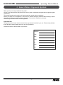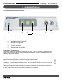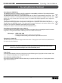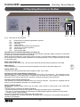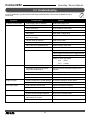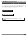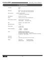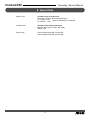
1
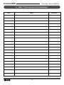
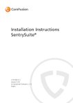
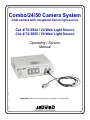
Combo/24/50 Camera System
CCD-camera with integrated Xenon light source
Cat. # 70-5924 / 24 Watt Light Source
Cat. # 70-5950 / 50 Watt Light Source
pmnl079
Rev. 2
08-2008
Operating / Service
Manual
IMPORTANT: Read all instructions before assembling or using this device.
An Employee-Owned Company
Combo/24/50
Operating / Service Manual
JEDMED Instrument Company was formed in July, 1978
and is entirely employee-owned (ESOP). Our goal is to
provide the best overall equipment packages to the medical
disciplines we serve. We thank you for all your support and
hope that your experience with this recent purchase will be
a rewarding one which will grow into a lasting relationship
with JEDMED.
Your suggestions on how we can improve our products and
services are always greatly appreciated. Please feel free to
contact us with your thoughts. We listen.
Sincerely,
JEDMED Instrument Company
© 2004 JEDMED Instrument Company
2
Combo/24/50
Operating / Service Manual
CONTENTS
Section
Page
OPERATION
OPERATING
Safety Reference/Place the Equipment...........................4
General Notes / Signs and Symbols................................5
Description of Equipment.................................................7
Operating Elements..........................................................8
Operating Elements on the Rear....................................10
Connecting and Operating the Equipment.....................11
SERVICE
Service Manual / Maintenance of the Equipment...........13
Troubleshooting..............................................................14
Cleaning / Disinfecting....................................................15
Technical Data................................................................16
Spare Parts....................................................................17
Table "Technical Service Information"............................18
Note: Specifications subject to change without notice.
3
Combo/24/50
Operating / Service Manual
1. Safety Reference / Place the Equipment
1.1 Safety Reference
Normal Use
The equipment may only be used with accessories, parts, and disposable items, which have been
designated by the manufacturer as suitable for the instrument or the safety use of which is proven.
User Qualification
The equipment may only be used by persons who have corresponding specialized qualification and who
have been instructed in the use of the equipment.
It is the user's responsibility to make sure the equipment is safe and operates properly before using the
equipment.
1.2 Place the Equipment
Unpacking / Items Included
Carefully unpack the equipment and accessories and remove them from their packing.
Check for missing items and evidence of shipping damage. File any complaints with the manufacturer or
supplier immediately. Retain the original packing materials for later use. These can come in handy when
the equipment must be transported.
Please verify immediately, after having unpacked the equipment, whether the delivery is complete. The
standard extent of delivery includes the following:
• control unit with light source and camera module
• camera head with cable
• operation manual
• video cable
• power supply cord
Safety Precautions at the Site of Installation
Always place the equipment on a solid base.
Make sure that air circulation is sufficient. Never cover the louver-type slots of the unit.
The equipment may be used only in rooms having electrical installations conforming to applicable national,
state and local electrical codes. The unit must be connected to the central potential equalization of the
operating theater or of the equipment trolley by means of a grounding cable. The device must be connected
to line voltage using the delivered protectively-earthed power supply cord.
The equipment may not be used in areas where there are dangerous flammable gases.
The equipment may only be connected to devices which also comply to the IEC601-1.
Never look directly in the light beam of the light source.
4
Combo/24/50
Operating / Service Manual
2. General Notes / Signs and Symbols
Thank you for your recent purchase of this product.
Like all of our other products, the product is the result of years of experience and great care in engineering and
manufacture.
This manual is designed to teach you the function and the operation of your equipment.
Before you switch on the equipment for the first time, please thoroughly read this manual and pay special
attention to all safety instructions so that endangering the user and/or the patient is prevented.
Please always store this manual with the equipment.
Equipment Data
The type label (rear of unit) contains technical data, type and serial number of your unit. Please always indicate
these data when ordering spare parts or in case of any questions.
Please enter here the technical data of your device!
Serial No.:
Type:
Date:
Class:
Hz:
Amp.:
Volt:
5
Combo/24/50
Operating / Service Manual
2. General Notes / Signs and Symbols (Continued)
Warranty
1 year according to our warranty conditions.
Opening the equipment or performance of any repairs or modifications of the equipment by unauthorized
persons shall release the manufacturer of any liability for its performance. Any such opening, repair or
modification performed during the warranty period shall void all warranty.
Normal wear is not included in the warranty.
The manufacturer shall be liable for failure or deterioration in the safe operation, operational reliability
and performance of this equipment only subject to the conditions that all assembly operations, system
expansions, readjustments or repairs to same have been performed by a person or persons duly authorized
by the manufacturer, that all electrical installations at the location of use meet applicable national and local
electrical codes and that the instrument has been used in accordance with its operating instructions at all
times.
Rights
All rights on this user manual, especially the rights of duplication and publication and the rights on translation,
are reserved. No part of this user manual may be reproduced by any means (by photostatic copy, microfilm
or other methods) without preceding written consent of the manufacturer or be reproduced, multiplied, or
published by means of electronic data processing.
The information given in the user manual can be changed or extended without notice and does not
represent any liability.
Errors and technical changes are expected.
Symbols
attention, important note!
safety note!
service
Signs
please read the enclosed instructions
unit model BF
beware of dangerous electrical voltage
connection for ground potential
alternating voltage
6
Combo/24/50
Operating / Service Manual
3. Description of the Equipment
This system is a combination of a high intensity Xenon light source and a color CCD camera in a common housing.
The Combo/24 unit contains a 24 Watt Xenon light source, while the Combo/50 contains a 50 Watt Xenon light
source. Both units come equipped with a 1/3" camera head and an electronic ANTI-MOIRE-FILTER for use with
flexible fiber scopes.
CCD Camera
The integrated CCD camera is a shutter-controlled camera. This means that the brightness of the monitor image is
controlled via an "electronic shutter." The shutter works with shutter-cycles between 1/50 and
1/2,000,000 sec.
If the longest shutter-cycle of 1/50 sec. is not sufficient to display the image in an adequate brightness, the video
signal is automatically boosted electronically by max. +30 dB. This electronic amplification is called AGC
(Automatic Gain Control).
You will achieve the best image quality when you have sufficient illumination and only the shutter is working. If the
AGC is added, this will cause additional noise on the monitor image.
Xenon Light Source
The integrated Xenon light source operates at constant power. The image brightness on the monitor is only
influenced by the shutter of the camera.
The Xenon bulb is mounted in a quick-exchange holder.
1/3" Camera Head
Included is a 1/3" 1-Chip camera head with a 3m cable. Only the head is soakable.
7
Combo/24/50
Operating / Service Manual
4. Operating Elements
4.1 Operating Elements on the Front Panel
1
2
4
3
5
6
7
Fig. 1: Control elements on the front panel
(1)
(2)
(3)
(4)
(5)
(6)
(7)
power switch / light source
push-button for WHITE BALANCE
push-button for WINDOW
push-button for AGC
connector for camera
light connection
push-buttons for anti-moire filter
Power Switch / Light Source (1)
The camera / light source is turned on by switching this switch. After unit is running by depressing power
button for 2 to 3 seconds light source will power down and camera will remain on. This will allow the use of
alternative light source if desired.
Push Button for WHITE BALANCE (2)
WHITE BALANCE is performed by pressing the corresponding push button.
First, aim the camera head on a homogeneously illuminated white sheet of paper or a well illuminated multicolor object. Simultaneously, press the push button. The current WHITE BALANCE is stored in memory and
is also saved when the camera is switched off.
Take notice that the paper-sheet or the multi-color object is not irradiated, which means that the grain structure
of the paper is visible on the monitor.
If white balance is done correctly, a natural color reproduction is guaranteed.
8
Combo/24/50
Operating / Service Manual
4. Operating Elements Continued
Push Button for WINDOW (3)
The WINDOW-function is turned on and off by pressing the corresponding push button. By pressing the button
you can change between three different window sizes.
The WINDOW-function carries out a light measurement that only affects a central window of the picture. That
means that in contrast to a standard measurement where the average brightness is integrated over the entire
picture size, only a center part of the image is taken to evaluate the average brightness; outer margins are
disregarded.
To activate the WINDOW-function, push the corresponding button. If the WINDOW-function is activated, a
yellow light inside the push button is illuminated. If the object to be viewed is in the center of the picture, you
should activate the WINDOW function. The object itself is correctly illuminated on the monitor, and the outer
margins of the screen are displayed proportionately darker or brighter.
Pressing of the button a second time deactivates the WINDOW-function.
Push-Button for Automatic Gain Control (AGC) (4)
For working under poor illumination conditions, the camera is equipped with an automatic gain control to increase
brightness. Under good illumination conditions you will see no effect on the screen.
AGC settings - ØØdB, 10dB, 18dB
- Push the AGC button once to show the current settings
- To change the AGC setting, press the button again within one second
Connector for Camera (5)
This terminal device is used for the plug of the camera cable. The plug has a small "nose" inside, which has to
face upwards when plugging in.
Attention! The control unit must be switched off when you connect or disconnect the camera cable
otherwise, permanent damage to the camera head may occur!
Light Exit (6)
Interchangeable adapters for the use of the light source with different types of light guides can be mounted in this
hole. Using the wrong adapter will damage the light exit.
Push Button for Anti-Moire Filter (7)
By pressing the window and AGC button simultaneously, the special moire filter turns on. Pressing these buttons
again will turn the filter off.
9
Combo/24/50
Operating / Service Manual
4.2 Operating Elements on the Rear
15
16
10 11
Fig. 2: Connectors on the rear panel
(9)
(10)
(11)
(12)
(13)
(14)
(15)
(16)
terminal device for potential equalization conductor
mains fuses drawer
mains plug
voltage selector
connector for video printer-remote (optional)
connector for PC-control (optional)
video terminal / Y/C
video terminal / BNC
Terminal Device for Potential Equalization Conductor (9)
Basically, the control unit is protectively-earthed (grounded) by the 3-pin power supply cord when it is connected
to a protectively-earthed wall socket, as prescribed.
When running the equipment in rooms which comply to class 1 or 2E according to MedGV, the control unit must
be connected to the central potential equalization of the operating theater or of the equipment trolley by means
of a grounding cable.
Mains Fuses Drawer (10)
In this drawer are the mains fuses. Use only fuses with same type and rating as specified on fuse label.
Mains Plug (11)
This terminal device (11) is used to connect the equipment to the mains by the power supply cord.
Voltage Selector (12)
The control unit can be operated with mains voltages of either 115V or 230V
Connector for Video Printer-Remote (optional) (13)
This connector (15) is used to connect a video printer (Sony UP) to the control unit. The connection cord is
delivered separately. If the video printer is connected, you can freeze the monitor image by pressing the front
push button on the camera head and you can print the image by pressing the rear push button.
Connector for PC-Control (optional) (14)
This connector (16) is used to control the device by a personal computer. If the device is equipped with this
feature, you will get additional information on a separate paper.
Video Connector (15) (16)
You can attach external output devices such as monitor, video recorder or video printer to the VIDEO-OUT
connectors.
The video signal is provided in two different standards.
• The BNC-connectors provide the video signal as VBS-signal (composite-signal, VHS-standard)
• The 4-pin Y/C connector provides the video signal as Hosiden-signal (separate conductors for chroma-andluminance-signal, S-VHS-standard).
The camera is equipped with both VBS-output and S-VHS output.
Whenever possible, use Y/C-signal rather than VBS-signal since it will achieve a much better image quality in
contrast to VHS-standard.
10
12
9
Combo/24/50
Operating / Service Manual
5. Connecting and Operating the Equipment
Before you connect the mains plug, check on the back of the equipment that the voltage indicated (in the square
panel above the mains socket) is the correct one.
voltage = 115VAC - indicator '115'
voltage = 230VAC - indicator '230'
If the incorrect voltage is indicated, then the equipment may under no circumstances be connected.
Before connecting a light cable into a light source adapter of the equipment, please ensure that you have the
correct plug and adapter. A plug that is too long or too thin can, for example, be pushed too far into the equipment
and can damage the sensitive lens inside. This will result moreover in considerable loss of light, in the same way
as a plug that is too short, or a plug of the wrong diameter, because of the wrong position of the contacts at the
light entry.
All wiring has to be done before switching on the equipment. After switching on a light source and the ensuing
ignition of the lamp, the equipment should remain switched on for at least 1/4 hour. A shorter shining
period will considerably shorten the life expectancy of the lamp. After switching off a light source however,
it may be immediately switched on again. A waiting period or cooling off period is not necessary.
Connect the Power Supply Cord
Use the protectively-earthed power supply cord, as supplied, to connect the control unit to the mains.
Connect the Camera Cable
Install the plug of the camera cable in the corresponding socket on the front panel as described above.
You can connect all lenses and endoscope couplers to the camera head, which are equipped with a
C-Mount thread. When you use objectives with CS-Mount thread, an additional intermediate ring is
necessary.
Connect the Light Guide
Verify whether the light guide fitting matches the delivered adapter. The light guide must snap in securely and
may not extend past the adapter end. Screw in the adapter and plug in the light guide.
Connect the External Output Devices
As described before, there are several standards of video signal available on the rear panel. Here you can
connect external output devices such as monitor, video recorder, video printer, etc. If you are using standard
VBS-signal (BNC-terminal), please always use high-quality 75Ω -coaxial cables. If the external output device has
a switchable 75Ω-termination resistor, you should switch this on. If you connect several devices in a row, only the
last device in the line needs to be terminated by the termination resistor. If the external device does not provide
such a termination resistor, you should connect the coaxial cable via a T-connection adapter. The open end of
the T-connection adapter is then terminated with the 75Ω-resistor.
Connect the Potential Equalization Conductor
Join the terminal device for potential equalization on the rear panel with the central potential equalization of the
operating theater or of the equipment trolley.
11
Combo/24/50
Operating / Service Manual
5. Connecting and Operating the Equipment (Continued)
5.1 Preparing for Operation
After having installed all connections, the camera can be set to work.
Switch on the control unit using the mains switch on the front panel (1).
The green lamp inside the switch lights up and the light source starts with full intensity.
If all other devices are switched on, a picture appears on the monitor which may or may not be incorrectly colored.
If color is incorrect, proceed with the white balance. First, aim the camera head on a homogeneously illuminated
white sheet of paper or a well-illuminated multi-color object. Simultaneously, press the push button. The current
WHITE BALANCE is stored in memory and is also saved when the camera is switched off. Take notice that the paper
sheet or the multi-colored object is not irradiated, which means that the grain-structure of the paper is visible on the
monitor.
Note: When turning on the light source and camera power switches there will be a noticeable delay before operation begins. This delay is normal and protects the electronic circuitry.
After the unit has been operating and is warm, there will be a significant delay (approximately 1 minute) before the lamp will re-ignite after being switched off and on again. This is also normal.
5.2 Working with the System
Now you can start the examination. There are no further adjustments necessary during operation. If the image is too
bright, activate the window feature.
If you have finished the examination, please switch off the control unit immediately afterwards in order to allow
maximum life expectancy of the lamp.
12
Combo/24/50
Operating / Service Manual
6. Service Manual / Maintenance of the Equipment
General Maintenance and Repair Information
The instructions and information given in this section are only for instructed personnel who are aware of the safety
precautions necessary for repair and maintenance of medical electronic devices.
The manufacturer refuses any liability for unauthorized repair and modification.
The manufacturer will provide those circuit diagrams, itemized parts listings, descriptions, sets of adjustment
instructions and other items of available documentation to suitably qualified user personnel duly authorized by the
manufacturer for their use in repairing those components of the equipment that have been designated by their
respective manufacturers as repairable.
The supply of such technical documentation relating to the equipment, however, shall not be construed as
constituting manufacturer's authorization of user's personnel, regardless of their levels of technical training, to
open or repair the equipment.
Explicitly exempted are those maintenance and repair operations scheduled in this manual.
6.1 Exchanging the Lamp
The built-in lamp is a Xenon low voltage lamp which is mounted in a cold light reflector. The manufacturer of the
lamp states the median life expectancy is 500 hours.
The lamp is stressed the most when it is switched on and off.
If the life expectancy has nearly expired, it will blow when switching on the device. Therefore, always provide a
spare lamp with the device, which can be installed as follows:
1.
2.
3.
4.
5.
6.
7.
8.
9.
10.
Switch off the equipment!
Pull out the mains plug!
Open the top cover by loosening the four (4) screws left and right
If the unit has run right before, the lamp is still very hot. Let the lamp cool down for about 10 minutes.
Pull out the lamp
Hold the lamp firmly and remove the lamp plug
Re-install the lamp plug to the new lamp
Re-install a new lamp in the holder
Re-install the cover
Plug in the mains plug and set the device to work
6.2 Exchanging the Fuses / Voltage Selection
Mains fuses are located on the rear panel of the control unit, directly above the mains terminal device in a small
drawer.
The window inside the drawer indicates the current voltage setting.
If you want to change the voltage settings, you have to change the fuses to the corresponding rating.
1. Pull out the mains plug!
2. Loosen the drawer by unfastening the two clamps located to the left and to the right of the drawer with a pointed tool and pull out the drawer.
3. Remove the two fuses.
4. Check the fuses. A blown fuse is indicated by the blackened glass cylinder or the visibly melted fuse
conductor. If necessary, check the fuse with an ohmmeter.
5. If the voltage setting should be changed, take out the white insert inside the fuse-drawer and re-insert
it turned over 180°. The window of the drawer now shows the valid voltage setting.
6. Install the corresponding fuses. You will find the right fuse ratings in section 6.2. They are also printed on the rear panel.
7. Re-install the fuse drawer.
8. Switch on the equipment again. If you have exchanged a defective fuse against a new one and the fuse
blows again, the unit is malfunctioning. If so, return the device to your dealer for testing and repair.
13
Combo/24/50
Operating / Service Manual
6.3 Troubleshooting
In case of malfunction, you should check the wiring connections first. Most errors are based on wrong
connections.
Symptom
no picture on the monitor
Possible Cause
mains supply cord not installed
Solution
install mains supply cord
mains switch off
switch on mains switch
mains fuses blown
check/exchange mains fuses
internal fuses blown
check/exhange internal fuses
lamp defect
check lamp / change lamp
lamp connector not installed correctly
after lamp change
check the correct installation
camera cable not installed
install camera cable
no mains voltage
check mains voltage
video cable not installed/defective
install/exchange video cable
monitor switched off
switch on monitor
malfunction inside CCU
check voltages:
mains voltage: as shown on the voltage selector
output voltage of power supply: +12VDC
voltage on CCU main board:
image too dark
J2-8 -9VDC
J2-11 +15VDC
window feature turned on
turn off window feature if not required
termination resistor on an external
output device switched on
switch off/remove termination resistors if not
required
lamp is too old
check lamp / change lamp
illumination not sufficient
increase illumination
monitor settings not in neutral position set monitor settings to neutral values
image too bright
monitor settings not in neutral position set monitor settings to neutral values
shutter not working
return device to manufacturer for repair
poor image quality
AGC emphasis causes noise
improve illumination conditions
illumination too dark
improve illumination conditions
bad colors
white balance not performed
perform white balance
monitor chroma settings misplaced
set chroma to a neutral value
no colors
Y/C terminal (if available) or cable defective / broken
check cable and Y/C terminal
monitor chroma settings misplaced
set chroma to a neutral value
14
Combo/24/50
Operating / Service Manual
6.4 Cleaning / Disinfecting
NOTE: PULL OUT THE MAINS PLUG!
All parts of the outer surfaces of the equipment are totally insensitive to all the usual cleaning and disinfecting
materials so that you can use any of these without limitation. Apply liquids using a soft cloth or soft blotting
paper in order to avoid scratches on the surfaces and in order to be able to control the amount of liquid.
With flammable liquids, like alcohol especially, you should apply with a cloth.
Do not autoclave any part of the equipment.
Do not allow any liquids to enter the equipment.
After cleaning with flammable liquids, leave the equipment to dry for one hour before it is switched on again. There is danger, for example, that an alcohol air explosive mixture could form after cleaning.
15
Combo/24/50
Operating / Service Manual
7 Technical Data
TV System
NTSC
PAL
Resolution
NTSC: 768 H x 494 V 470 TV-lines horizontal
PAL: 752 H x 582 V 470 TV-lines horizontal
Video Terminals
1 X VBS (1 Vpp/75Ω), BNC
1 X Hosiden (Y/C), Mini-DIN-jack
White Balance
Automatic, with memory
Shutter
Floating, cycles from 1/50 to 1/2,000,000 sec.
Freeze Memory (optional)
Amount of pixels: 752 H x 580 V
Frame Storage
Color depth: 8 bit
AGC
Automatic
Light Measurement
Integral
Max. emphasis +30db
Power Supply
115 VAC ± 10%
230 VAC ± 10%
Power Consumption
70 Watts 170 Watts
Fuses
Located on rear of control unit
Fine fuses, 5x20mm, delay acting (slow-blow)
For 115 VAC: 2.5A, 2 pieces
(same for Combo/24 or Combo/50)
For 230 VAC: 1.25A, 2 pieces
Certificates
CE
Dimensions
Control Unit: W X H X D = 355 x 110 x 320 mm
Weight
(Combo/24)
(Combo/50)
Control Unit: Shipping Weight:
16
4kg (approximately)
5.5kg (approximately)
Combo/24/50
Operating / Service Manual
8. Spare Parts
Mains Fuses
Located on rear of control unit
Fine fuses, 5x20mm, delay acting (slow-blow)
For 115VAC: 2.5A
(same for Combo/24 or Combo/50)
For 230VAC: 1.25A
Internal Fuses
Located on the camera control pcb
Miniature fuses, pitch 2.54mm, fast acting
300mA, 1.6A
Spare Lamp
Xenon reflector lamp 24W (Combo/24)
Xenon reflector lamp 50W (Combo/50)
17
Combo/24/50
Operating / Service Manual
9. Table "Technical Service Information"
DATE
CHECK
18
SIGNATURE
Combo/24/50
NOTES
19
Operating / Service Manual
5416 JEDMED Court
St. Louis, MO 63129
(314) 845-3770 phone
(314) 845-3771 fax
e-mail: [email protected]
website: www.JEDMED.com