1
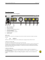
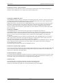
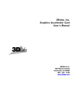
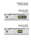
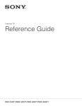
Operation manual Service manual V ETCCD 100 Endoscopy video camera with integrated 100Watt xenon lightsource T e l . + E ic k e m 4 E 9 e y e r - M e d iz in t e c h n ik f ü r lt a s t r . 8 7 8 5 3 2 T u t t l in g e n , G ( 0 ) 7 4 + 6 4 1 9 / ( 9 0 6 ) 5 7 8 4 0 6 - 1 0 / F 9 a6 x5 : 8 0 - 9 0 I n t e r n e t : w w w . e i c k e m e y e T ie r E r . d R M e Page 2 of 24 Operation manual VETCCD 100 This manual contains information protected by copyright laws. All rights reserved. Manual may not be copied or duplicated, in its entirety or in part. We reserve the right to make technical changes on device prior notice. Copyright Eickemeyer 10.2005 SERVICE ADDRESS: Eickemeyer KG Eltastr. 8 D-78532 Tuttlingen GERMANY Telephone: Fax: +49 7461 965 80-0 +49 7461 965 80-90 BA-E-VETCCD100-Eickemeyer 23-12-2005.doc Rev 3.0 Operation manual VETCCD 100 Page 3 of 24 Table of contents Operation manual.............................................................................................................................................1 GENERAL ADVISES ............................................................................................................................................4 DATA OF THE EQUIPMENT ............................................................................................................................................4 RIGHTS....................................................................................................................................................................4 WARRANTY .............................................................................................................................................................4 SERVICE, REPAIRS AND MODIFICATIONS........................................................................................................................5 LIABILITY.................................................................................................................................................................5 DISPOSAL.................................................................................................................................................................5 SAFETY REFERENCE / PLACE THE EQUIPMENT......................................................................................6 NORMAL USE............................................................................................................................................................6 USER QUALIFICATION..................................................................................................................................................6 UNPACKING / ITEMS INCLUDED.....................................................................................................................................6 ...............................................................................................................................................................................6 SAFETY PRECAUTIONS OF INSTALLATION........................................................................................................................6 STORAGE AND OPERATION CONDITIONS..........................................................................................................................6 SIGNS & SYMBOLS..............................................................................................................................................7 SYMBOLS..................................................................................................................................................................7 SIGNS.......................................................................................................................................................................7 DESCRIPTION OF THE EQUIPMENT.............................................................................................................8 OPERATING ELEMENTS...................................................................................................................................9 OPERATING ELEMENTS ON THE FRONTPANEL...................................................................................................................9 OPERATING ELEMENTS ON THE REAR...........................................................................................................................11 CONNECTING AND OPERATING..................................................................................................................12 CONNECTING THE EQUIPMENT....................................................................................................................................12 OPERATING THE EQUIPMENT.......................................................................................................................................13 SERVICE MANUAL............................................................................................................................................14 GENERAL MAINTENANCE AND REPAIR ADVICE...............................................................................................................14 SERVICE INTERVALS.................................................................................................................................................14 SELECTION OF THE LINE VOLTAGE SETTING...................................................................................................................14 EXCHANGE OF THE MAINS FUSES.................................................................................................................................14 EXCHANGING THE LAMP............................................................................................................................................15 TROUBLESHOOTING..................................................................................................................................................16 CLEANING / DISINFECTING........................................................................................................................................16 WIRING DIAGRAM............................................................................................................................................18 TECHNICAL DATA............................................................................................................................................19 SPARE PARTS...........................................................................................................................................................19 TABLE ‘TECHNICAL SERVICE-INFORMATION’......................................................................................20 APPENDIX............................................................................................................................................................21 ELECTROMAGNETIC COMPATIBILITY (EMC)...............................................................................................................21 Rev 3.0 BA-E-VETCCD100-Eickemeyer 23-12-2005.doc Page 4 of 24 Operation manual VETCCD 100 General advises Like all of our other products, this product is the result of years of experience and great care in engineering and manufacture. This manual is destined to learn you understanding the function and the operation of your equipment. Before you switch on the equipment for the first time, please thoroughly read this manual and pay special attention to all safety instructions, so that endangering for the user and the patient is precluded. Please always store this manual with the equipment. Before use, read this manual thoroughly. An insufficient understanding of the dangers, warnings, cautions, and informations in this manual can result in death, serious injury, or equipment damage. This product complies with the requirements of Directive 93/42/EEC concerning medical devices. Data of the equipment The type label (rear of unit) contains technical data, type and serial number of your unit. Please always indicate these data when ordering spare parts or in case of any question. Please enter here the technical data of your device! • Serial No.: ______________________________ • Type: ______________________________ • Date: ______________________________ • Class: ______________________________ • Hz: ______________________________ • Amp.: ______________________________ • Volt: ______________________________ Rights All rights on this user manual, especially the rights of duplication and publication and the rights on translation are reserved. No part of this user manual may be reproduced by any means (by photostatic copy, microfilm or other methods) without preceding written consent of the manufacturer or be reproduced, multiplied or published by means of electronic data processing. The information given in this user manual can be changed or extended without notice and do not represent any liability. Errors and technical changes excepted. Warranty 1 year according to our warranty conditions. Opening the equipment or performance of any repairs or modifications of the equipment by unauthorised persons shall relive the manufacturer of any liability for its performance. Any such opening, repair or modification performed during the warranty period shall void all warranty. Wear parts are not included in the warranty. The firm of the manufacturer shall be liable for failure or deterioration in the safe operation, operational reliability and performance of this equipment only subject to the conditions, that all assembly operations, system expansions, readjustments or repairs to same have been performed by a person or persons duly authorised by the BA-E-VETCCD100-Eickemeyer 23-12-2005.doc Rev 3.0 Operation manual VETCCD 100 Page 5 of 24 manufacturer, that all electrical installations at the location of us meet applicable national and local electrical codes and that the instrument has been used in accordance with its operating instructions at all times. Service, Repairs and Modifications In conformity with the international safety regulations valid for medical devices, all activities such as check ups, repairs, modifications, calibrations etc. may only be carried out by the manufacturer or by explicitly authorized personnel. All services carried out must be entered in the „Technical Service Notes“ at the back of the user manual. Liability As manufacturer of the device, we only consider ourselves liable for safety, reliability and performance of the unit, if • assembly, re-adjustment, modifications or repairs are performed by persons authorised by us • the electric installation of the respective room corresponds to the regulations of VDE 0107 the instructions found in the user manual are strictly observed when operating the unit. Disposal In accordance with European Directive 2002/96/EC on Waste Electrical and Electronic Equipment, this symbol indicates that the product must not be disposed of as unsorted municipal waste, but should be collected separately. Refer to your distributor resp. the manufacturer for return and/or collection system available in your country. Rev 3.0 BA-E-VETCCD100-Eickemeyer 23-12-2005.doc Page 6 of 24 Operation manual VETCCD 100 Safety reference / Place the equipment Normal use The equipment may only be used with accessories, wearing parts and disposable items, which have been designated by the manufacturer suitable for the instrument or the safety use of which is proven. User qualification The equipment may only be used by persons, who have a corresponding specialised qualification and who have been instructed in use of the equipment. It is the user’s responsibility to make sure, the equipment is safe and operates properly before using the equipment. Unpacking / items included Carefully unpack the equipment and accessories and remove it from their packing. Check for missing items and evidence of shipping damage. File any complaints with the manufacture or supplier immediately. Retain the original packing materials for later use. These can come in handy, when the equipment must be transported. Please verify immediately after having unpacked the equipment, whether the delivery is complete. The standard extent of delivery includes of the following: Ø Ø Ø Ø Ø Control unit Watertight camera head with 3m cable Video cable (Y/C, BNC) Power supply cord Manual Safety precautions of installation Always place the equipment on a solid base. The equipment may be used only in rooms having electrical installations conforming to applicable national, state and local electronical codes. The unit must be joined to the central potential equalisation of the operating theatre or of the equipment trolley by means of a grounding cable. The device must be connect to line voltage using the delivered protectively earthed power supply cord. Storage and operation conditions Storage temperature: Operation temperature: -20°C to +60°C +10°C to +40°C rel. humidity: storage: 10% to 90% operation: 30% to 75% Air pressure: storage: 600 mbar to 1300 mbar operation: 700 mbar to 1060 mbar BA-E-VETCCD100-Eickemeyer 23-12-2005.doc Rev 3.0 Operation manual VETCCD 100 Page 7 of 24 Signs & symbols Symbols Attention, important note! Safety note Service Signs Please read the enclosed instructions ! Unit model BF Beware of dangerous electrical voltage ! Connection for ground potential ~ Alternating voltage Rev 3.0 BA-E-VETCCD100-Eickemeyer 23-12-2005.doc Page 8 of 24 Operation manual VETCCD 100 Description of the equipment The equipment you have pruchased features a state-of-the-art colour CCD camera, which was especially designed for use with endoscopic applications. In combination with the built-in high-intensity xenon illumination, the device offers the user a compact unit for optimal image quality in nearly every endoscopic discipline. CCD camera Full digital signal processing ensures true colour reproduction. The camera consists of a control unit and a complete watertight camera head. Located at the front of the ergonomically shaped camera head, there is a C-Mount-Thread adaptation, where you can connect usual lenses, vario-focus TV-couplers or other couplers to connect the endoscope. Located inside the camera head is the CCD-chip, which takes the image and converts it into electric signals. These signals are conducted through the camera cable to the control unit. Inside the control unit, the image data is processed and is provided either as Standard-VBS-Signal (BNCconnector, VHS-standard) or as Hosiden-Signal (Y/C-signal, Mini-DIN-connector, S-VHS-standard) on the rear panel for displaying on the monitor and/or other devices, such as videoprinter, videorecorder, etc.). The image-brightness is controlled by an electronic shutter, which is working with a shutter-cycle at minimum of 1/100.000 sec., so that even when the image is totally irradiated a well-balanced video picture is delivered to the monitor. If the image is extremely dark illuminated, the shutter cycle becomes so high, that it is impossible to display a flicker-free picture. In this case, the videosignal is emphases electronically by max. +30dB. This electronic emphasis is called AGC (Automatic Gain Control). It has to be taken into account, that the noise on the picture is increased, when the AGC is working. Xenon lightsource The built-in 100 Watt xenon illumination features a high-intensity xenon lamp, which is installed in a reflector. The lamp designed is optimised for endoscopic applications. The colour temperature equals daylight quality with a colour temperature of 5.600 K. The equipment is desinged by the latest standards of security for medical equipment (IEC 60601-1 ff) and complies with the demands of CE. The device is classified as class I product according to guideline 93/42/EWG. BA-E-VETCCD100-Eickemeyer 23-12-2005.doc Rev 3.0 Operation manual VETCCD 100 Page 9 of 24 Operating elements Operating elements on the frontpanel P O W I I O O E R I N T E N S I T Y B - 1 1 2 3 4 5 6 7 8 9 9 2 3 4 W H I T E W L A N C E A 5 I N 6 D O W C 7 A M I N E R 8 Mains switch lightsource Mains switch camera Connector fibrescope Push buttons “increase/decrease intensity” Push button WHITE BALANCE Push button WINDOW Push button Anti-Moiré or BOOST Connector camera Switch air pump Mains switch The control unit is turned on by switching the mains switch. The mains switch has two different switching positions: I ON switched on O OFF switched off When the control unit is switched on, this is indicated by the up-light green lamp inside the switch. Connector for camera cable This connector is used for attachment of the plug of the camera cable. The plug can only be plugged in a certain position. This is achieved by a small nose on the top of the plug. The red mark on the 19-pin-plug must correspond with the red mark on the socket to install the plug. The plug fastens automatically when completely plugged in. To unfasten the plug, grip the knurled part of the plug and pull the plug out of the socket. Connector for fibrescope For lightguide connection, there are interchangeable adapters available for all brands of lightguides. For gastroscopic applications, the lightsource comes equipped with a special adapter with integrated air supply for your gastroscope brand. Using the wrong lightguide or adaptor can damage the lightsource and the accessories and threats the patient. Rev 3.0 BA-E-VETCCD100-Eickemeyer 23-12-2005.doc A Page 10 of 24 Operation manual VETCCD 100 Push buttons: increase / decrease intensity These buttons are used to adjust the intensity of the output in manual mode. If the mechanical diaphragm is opened or closed completely a yellow light in the switch will indicate this. Push button : WHITE BALANCE The WHITE BALANCE is done by pressing the corresponding push button. Therefore, aim the camera head on a homogeneously illuminated white sheet of paper or a well illuminated multi-colour object. Simultaneously, press the push button once. The button then will flash until the WHITE BALANCE is finished. The current WHITE BALANCE is stored in memory and is also saved, when the camera is switched off. Take notice, that the paper-sheet or the multi-colour object is not irradiated, that means, e.g. that the grain-structure of the paper is visible on the monitor. If WHITE BALANCE is done correctly, a natural colour reproduction is guaranteed. The current attitude is stored in the camera and remains after switching off. Push button : WINDOW The WINDOW-function is turned on and off by pressing the corresponding push button (5). The WINDOW-function carries out a light measurement that only affects a central window of the picture. That means, that in contrast to standard measurement, where the average brightness is integrated over the entire picture size, only a centre part of the image is taken to evaluate the average brightness, outer margins are disregarded. To activate the WINDOW-function, push the corresponding button. If the WINDOW-function is activated, a yellow light inside the push button is up-light and a light-grey rectangle appears on the monitor picture for a short time, that represents the area, that is taken for brightness evaluation. If the object to be regarded is in the centre of the picture, you should activate the WINDOW-function. The object itself is displayed correctly illuminated on the monitor and the outer margins of the screen are displayed proportionately darker or brighter. Anewed pressing of the button deactivates the WINDOW-function. Push button: Anti-Moire Filter (optional) This electronically filter should be used while working with flexible fibre scopes, to reduce the Moiré-Effect and increase the picture quality. By pushing the Anti-Moiré button, the anti-moire funktion are switched on. The actual status is indicated by the lighting button. Push button: BOOST (optional) For working under bad illumination conditions, the camera is equipped with a Boost-function to increase image brightness. Press the corresponding button to activate the function. Under good illumination conditions you’ll see no effect on the screen. The actual status is indicated by the lighting button. Switch air pump The integrated pump is switched on and off by using the corresponding switch. Switch on the pump only right before the use of it and switch it off right after. The pump is maintenance-free. Make sure, no dirt and liquids can get into the adaptor. BA-E-VETCCD100-Eickemeyer 23-12-2005.doc Rev 3.0 Operation manual VETCCD 100 Page 11 of 24 Operating elements on the rear 1 0 1 21 3 1 10 11 12 13 14 1 1 4 Terminal device for potential equalisation conductor Video output terminal (VBS / S-VHS) Mains terminal device Fuse holder Voltage selector Terminal device for potential equalisation conductor Basically, the control unit is protectively earthed by the 3-pin power supply cord when it is connected to a protectively earthed wall socket, as prescribed. When running the equipment in rooms which comply to class 1 or 2E according to MedGV, the control unit must be joined to the central potential equalisation of the operating theatre or of the equipment trolley by means of a grounding cable. Video output terminals You can attach external output-devices such as monitor, videorecorder or videoprinter to the VIDEOOUT connectors. The videosignal is provided in two different standards. 1. The BNC-terminal provide the videosignal as VBS-signal (composit-signal, VHS-standard). 2. The 4-pin-Y/C-terminal provides the videosignal as Hosiden-signal (separate conductors for chroma- and luminance-signal, S-VHS-standard). Both video outputs are available simultaneously, so that both standards can be used at one time. You should better use the Y/C-signal than VBS-signal if possible, because you will achieve a much better image quality in contrast to standard VHS-standard. Mains terminal device The plug of the power supply cord is connected to the mains terminal device. Use only the delivered power supply cord. Mains fuses / voltage selector This little drawer right above the mains terminal device contains the mains fuses. The window inside the drawer shows the currently selected mains voltage. You have to control whether your mains voltage corresponds with the selection shown in the window. Rev 3.0 BA-E-VETCCD100-Eickemeyer 23-12-2005.doc Page 12 of 24 Operation manual VETCCD 100 Connecting and operating Connecting the equipment Before you connect the mains plug, check on the back of the equipment that the voltage indicated (in the square panel above the mains socket) is the correct one. voltage = 230VAC indicator ‘230’ voltage = 115VAC indicator ‘115’ If the incorrect voltage is indicated then the equipment may under no circumstances be connect. Before connecting a light cable into a light source adapter of the equipment, please ensure that you have the correct plug and adapter. A plug that is too long or too thin can for example be pushed too far into the equipment, and can damage the sensitive diaphragm or lens inside. This will result moreover in considerable loss of light, in the same way as a plug that is too short, or a plug of the wrong diameter, because of the wrong position of the contacts at the light entry. Always install all connections before switching on the equipment ! Connect the power supply cord ! Use the delivered protectively earthed power supply cord to connect the control unit to the mains. Please check before, whether the current voltage selection matches your local mains voltage. Connect a fibrescope ! Verify, whether the installed adapter matched the fibrescope you want to connect. Plug in the light plug of the fibrescope. Thus the air connection is automatically fixed. Connect the water bottle to the fibrescope (if necessary). There is a holder for the water bottle installed at the left side of the housing. Connect the potential equalisation conductor! Join the terminal device for potential equalisation on the rearpanel with the central potential equalisation of the operating theatre or of the equipment trolley. Connect the camera cable ! Install the plug of the camera cable in the corresponding socket on the frontpanel as described above. You can connect all lenses and endoscope couplers to the camera head, which are equipped with a C-Mount-Thread or CS-Mount-Thread. When you use objectives with CS-Mount-Thread, an additional intermediate ring is necessary. Your dealer supplies various lenses and couplers for your special requirements. Connect the external output devices ! As described before, there are several standards of videosignal available on the rearpanel. Here you can connect external output devices such as monitor, videorecorder, videoprinter, etc. If you are using standard VBS-signal (BNC-terminal), please always apply high-quality 75Ω-coaxial cables. If the external output device has a switchable 75Ω-termination resistor, you should switch this on. If you connect several devices in a row only the last device in the line needs to be terminated by the termination resistor. If the external device does not provide such a termination resistor, you should connect the coaxial cable via a Tconnection-adapter. The open end of the T-connection adapter is then terminated with the 75Ω-resistor. We recommend the use of the delivered S-VHS-cable. BA-E-VETCCD100-Eickemeyer 23-12-2005.doc Rev 3.0 Operation manual VETCCD 100 Page 13 of 24 Operating the equipment After having installed all connections, the camera can be set to work. Switch on the control unit using the mains switch on the frontpanel. The green lamp inside the switch lights up and the lightsource starts with full intensity. If all other devices are switched on, a picture appears on the monitor, which is possibly still wrong coloured. Now proceed with the WHITE BALANCE. Therefore, aim the camera head on a homogeneously illuminated white sheet of paper or a well illuminated multi-colour object. Simultaneously, press the push button. The current WHITE BALANCE is stored in memory and is also saved, when the camera is switched off. Take notice, that the paper-sheet or the multi-colour object is not irradiated, that means, e.g. that the grain-structure of the paper is visible on the monitor. Now you can start the examination. There are no further adjustments necessary during operation. If the image is too bright, activate the window feature. If you have finished examination, please switch off the control unit right afterwards, in order to allow a maximum life expectancy of the lamp. Rev 3.0 BA-E-VETCCD100-Eickemeyer 23-12-2005.doc Page 14 of 24 Operation manual VETCCD 100 Service manual General maintenance and repair advice The instructions and information given in this chapter are only for instructed personnel, who are aware of the safety precautions necessary for repair and maintenance of medical electronic devices. The manufacturer refuse any liability for unauthorised repair and modification. The manufacturer will provide those circuit diagrams, itemised parts listings, descriptions, sets of adjustment instructions and other items of available documentation to suitably qualified user personnel duly authorised by the manufacturer for their use in repairing those components of the equipment that have been designated by their respective manufactures as reparable. Only the supply of such technical documentation relating to the equipment shall not be construed as constituting manufacturer’s authorisation of user’s personnel, regardless of their levels of technical training, to open or repair the equipment. Explicitly exempted here from are those maintenance and repair operations described in this manual. Service Intervals The equipment should be controlled on save function by authorized service personal at least one time the year. These controls should be done every time too, when a lamp is exchanged. Selection of the line voltage setting To set the correct voltage proceed as follows: • PULL OUT THE MAINS PLUG! • Using a small screwdriver or other sharp instruments, the black rectangular board above the socket can be lifted out. • The white panel with the fuse can be taken out and turned 180°, and then put back into the fuse container. • After that the rectangular fuse board can be put back (the small nose of the board facing downwards) and firmly pressed until it has completely snapped in. Now the small white panel should show the correct voltage. Exchange of the mains fuses The mains fuses are located on the rearpanel of the control unit, right above the mains terminal device in a small drawer. If you need to exchange the mains fuses, proceed as follows: Ø PULL OUT THE MAINS PLUG ! Ø Loosen the drawer by unfastening the two clamps located to the left and to the right of the drawer with a peaked tool and pull out the drawer. Ø Take out the fuses. Ø Check the fuses. A blown fuse is indicated by the blackened glass cylinder or the visibly melted fuse conductor. If necessary, check the fuse with an ohmmeter. Ø Install the corresponding fuses. Ø Re-install the fuse-drawer. Switch on the equipment again. If you have exchanged a defective fuse against a new one and the fuse blows again, the unit has an error. In this case, you must return the device to your dealer for testing and repair. BA-E-VETCCD100-Eickemeyer 23-12-2005.doc Rev 3.0 Operation manual VETCCD 100 Page 15 of 24 Exchanging the lamp The lamp is especially stressed when switched on or off. Thus, it will blow when switching on or off the lightsource. The only part subject to wastage in the equipment are the lamp. In order to secure safe operation of the equipment, the lamp should be changed after expire of this operation time. Attention: The lamps are filled with xenon gas at very high pressure! Lamps must be handled with the same care and caution given any vessel containing these levels of pressure! A hazard exists if the window or ceramic fractures and may cause explosive mechanical failure. Face shields or proper safety glasses are recommended during all handling operations! In order to exchange the lamp, proceed as follows: • • • • • • • • • • • Switch off the equipment ! Pull out the mains plug ! Unscrew the five screws located on both sides and rear of the housing and lift off the cover ! If the lamp has burned right before, it may be still very hot. Let it cool down before proceeding ! Disconnect the lamp connector Loosen the hand screw and push up the lamp guard. Pull out the lamp backwards out of its holder ! Insert a new lamp into the holder and close the lamp guard like before. Reconnect the lamp cable ! Install the cover. Take care, that the grounding cable of the cover is installed properly. Fasten the cover with the screws, plug in the mains plug and switch on the equipment. t o p + v i e w c a b l e k n u r l e d s c r e w c a b le h e a d l a m p b o d y l a m p g u l a m Rev 3.0 a r d p p l u g f i x e d j a c k BA-E-VETCCD100-Eickemeyer 23-12-2005.doc Page 16 of 24 Operation manual VETCCD 100 Further maintenance in conjunction with lamp change After operation, dust may have been sucked through the fan blades into the equipment, depending on the conditions in the environment. This dust should be removed from the equipment with a vacuum cleaner using a small nozzle attachment. Dust can sometimes cling quite firmly to the fan blades. This should then be cleaned with a cloth and a little alcohol/spirits. Likewise dust settles on the heat protective filter, this should also be cleaned with a soft cloth or blotting paper and pure alcohol or spirits. Concerning use of flammable liquids, pay attention to safety precautions. Attention: Don’t throw the old lamp undamaged into the garbage waste! The lamps will be explode ! Envelop the old lamps into a thick cloth and smash up with a hammer or send used lamps back to the manufacturer for disposal ! Troubleshooting In any case of malfunction, you should check the wiring at first. Most errors are based on wrong wiring. The last column shows the referring chapter. Symptom no picture on the monitor Possible cause install mains supply cord mains switch off switch on mains switch mains fuses blown check/exchange mains fuses internal fuses blown check/exchange internal fuses camera cable not installed install camera cable no mains voltage check mains voltage video cable not installed/defective install/exchange video cable monitor switched off switch on monitor check voltages: mains voltage: as shown on the voltage selector output voltage of power supply: +12VDC voltage on CCU main board: J3-13 +15VDC J3-14 - 9VDC malfunction inside CCU Bild zu dunkel / image too dark Bild zu hell / image too bright schlechte Bildqualität schlechte Farben / bad colours keine Farben / no colours window feature turned on turn off window feature if not required or change window settings (use OSD) peak feature turned on turn off peak feature if not required (use OSD) termination resistor on an external output device switched on switch off/remove termination resistors if not required illumination not sufficient increase illumination turn on AGC or increase amplification (use OSD) turn on AGC or increase amplification (use OSD) monitor settings not in neutral position set monitor settings to neutral values monitor settings not in neutral position set monitor settings to neutral values shutter not working return device to manufacturer for repair BNC-terminal in use use Y/C-terminal for better quality AGC emphasis too high decrease AGC emphasis (use OSD) illumination too dark improve illumination conditions WHITE BALANCE not done do WHITE BALANCE monitor chroma settings misplaced set chroma to a neutral value colour settings misplaced set colour settings to desired value (use OSD) colour settings misplaced set colour settings to desired value (use OSD) Y/C-terminal or cable defective/broken check cable and Y/C-terminal monitor chroma settings misplaced set chroma to a neutral value Cleaning / Disinfecting NOTE: PULL OUT THE MAINS PLUG ! BA-E-VETCCD100-Eickemeyer 23-12-2005.doc Remedy mains supply cord not installed Rev 3.0 Operation manual VETCCD 100 Page 17 of 24 All parts of the outer surfaces of the equipment are totally insensitive to all the usual cleaning and disinfecting materials, so that you can use any of these without limitation. Apply liquids using a soft cloth or soft blotting paper, in order to avoid scratches on the surfaces and in order to be able to control the amount of liquid. With flammable liquids like alcohol especially, you should apply with a cloth. Do not let any liquid get into the equipment. After cleaning with flammable liquids, leave the equipment to dry for one hour, before it is switched on again. There is danger for example that an alcohol-air explosive mixture could form after cleaning. Improper and/or incomplete reprocessing can cause infection of the patient and/or medical personnel. For medical applications the device with a waterproof camera head is supplied. The camera head can be put for disinfection purposes into a disinfection solution. Please note, the camera cable may be inserted only with screwd on cap! Before immersing the camera cable, you have to screw the sealing-cap onto the plug. Take care of correct position of the thick red sealing. Improper and/or incomplete reprocessing can cause infection of the patient and/or medical personnel. The camera-cable must not be autoclaved ! Rev 3.0 BA-E-VETCCD100-Eickemeyer 23-12-2005.doc Page 18 of 24 Operation manual VETCCD 100 Wiring diagram BA-E-VETCCD100-Eickemeyer 23-12-2005.doc Rev 3.0 Operation manual VETCCD 100 Page 19 of 24 Technical data TV-system • PAL • NTSC Resolution active pixels: 752 H x 582 V (PAL) 768 H x 494 V (NTSC) TV resolution 470 lines Video-output 1 x VBS (1Vpp/75Ω), BNC 1 x Hosiden (Y/C), Mini-DIN-connector Whitebalance automatically,with data-hold Shutter automatically, shutter-speed 1/50 to 1/100.000 sec. AGC automatically, max. emphasis +30dB Light measurement Integral (Standard) WINDOW Power supply 230 VAC ± 10% or 115 VAC ± 10% Power consumption 100 W Mains fuses fine fuses, 5x20mm, delay acting 115 VAC : 2 x 5,0 A 230 VAC : 2 x 2,5 A Lightguide connector all lightguides connectable using interchangeable adapters Lamp XENON reflector lamp 100 W, XBO R100W/45C Colour temperature 5.600 K Dimensions control unit 355x110x325mm (WxHxD) camera head Ø 29mm, length 56 mm Weight control unit 5,5 kg camera head approx. 70 g (without cable) Class / Type 1 / BF Manufactured and tested acc. IEC 601-1 / CE; EN 60601-1; 93/42/EEC Spare parts Mains fuses fine fuses, 5x20mm, delay acting 115 VAC : 2 x 5,0 A 230 VAC : 2 x 2,5 A Lamp XENON Reflektorlampe 100 W, XBO R100W/45C Rev 3.0 BA-E-VETCCD100-Eickemeyer 23-12-2005.doc Page 20 of 24 Operation manual VETCCD 100 Table ‘Technical service-information’ Date BA-E-VETCCD100-Eickemeyer 23-12-2005.doc Check Signature Rev 3.0 Operation manual VETCCD 100 Page 21 of 24 Appendix Electromagnetic Compatibility (EMC) Precautionary measures Electromedical devices are subject to special precautionary measures concerning electromagnetic compatibility (EMC). This device is to be used for the purposes described in the operation manual and has to be installed, set up, and operated in compliance with the EMC guidelines. Impact of mobile and portable RF communication devices The emission of high frequency by mobile communication devices may impact the function of the electromedical device. Operating such mobile communication devices (e.g. cell phones, GSM phones) in the proximity of the electromedical device is prohibited. Electrical connections Connections between such plugs and sockets may not be established without first implementing ESD precautionary measures. ESD precautionary measures The following are ESD precautionary measures: - Connect all electrical equipment to be connected to the device to a potential equalisation system (via PE). - Use only the equipment and accessories mentioned in the operation manual. The staff have to be informed about and trained in ESD precautionary measures. The VETCCD 100 should be operate in an enviroment as stadet below. The user have to make sure that the VETCCD 100 will be operate in such enviroment. Manufacturer declaration – Electromagnetic application Noise emmission measurement Correspondence Electromagnetic enviroment - Guide HF- Emission acc. to CISPR Group 1 The VETCCD 100 used HF-energy solely for internal functions. Therefore, the HF-emission is very low and interferences with adjacent electronical equipment are improbable. HF- Emission acc. to CISPR Class B Harmonics acc. to IEC 61000-3-2 Class A Voltage fluctuations / Flicker acc. to IEC 61000-3-2 The VETCCD 100 is adapted for use in all facilities including living areas and such facilities with public utility provider. unapplicable Manufacturer declaration – Electromagnetic noise immunity Noise immunity tests IEC 60601 – test level Correspondence level Electrostatic discharge (ESD) acc. to IEC 610004-2 ± 6 kV contact discharge ± 6 kV contact discharge ± 8 kV air discharge ± 8 kV air discharge ± 2 kV for mains lines ± 2 kV for mains lines ± 1 kV for Input and output lines ± 1 kV for Input and output lines Quick transient electrical disturbances / Bursts acc. to 61000-4-4 Rev 3.0 Electromagnetic enviroment Guide Floors should be consist of concrete or wood or furnished with ceramic tiles. If the floor furnished with synthetic material, the relative air humidity should be 30 % average. The quality of mains voltage should be comply typical mains voltage of business or hospital enviroment. BA-E-VETCCD100-Eickemeyer 23-12-2005.doc Page 22 of 24 Surge voltage acc. to IEC 61000-4-5 Acc. to IEC 61000-4-11 Magnetic field by supply frequency (50 / 60 Hz) acc. to IEC 61000-4-8 Operation manual VETCCD 100 ± 1 kV push-pull voltage ± 1 kV push-pull voltage ± 2 kV push-push voltage ± 2 kV push-push voltage < 5% UT (> 95% UT collaps)for ½ period < 5% UT (> 95% UT collaps)for ½ period < 40% UT (> 60% UT collaps)for 5 periods < 40% UT (> 60% UT collaps)for 5 periods < 70% UT (> 30% UT collaps)for 25 periods < 70% UT (> 30% UT collaps)for 25 periods < 5% UT (> 95% UT collaps)for 5 sec. < 5% UT (> 95% UT collaps)for 5 sec. 3A/m 3A/m The quality of mains voltage should be comply typical mains voltage of business or hospital enviroment. The quality of mains voltage should be comply typical mains voltage of business or hospital enviroment. If the user of the VETCCD 100 demand continued functions also by appearance of interrupts, it will be recommended to operate the VETCCD 100 by non-interruptable power supply. Magnetic fields by line frequency should be correspond to typical values you will find in business and hospital enviroments. Note: UT is the line AC voltage before using the test level. Manufacturer declaration – Electromagnetic noise immunity Noise immunity test IEC 60601 – test level Correspondence level Electromagnetic enviroment - Guide Portable and mobile radio transmitter should not be use within the recommended safety distance to the VETCCD 100 (including the lines)! The recommended safety distance will be calculate by the appropriate transmitting frequency formula. Recommended safety distance: Guided HF-disturbances acc. to IEC 61000-4-3 3 Veff 150 KHz to 80 KHz Radiated HF-disturbances acc. to 3 V / m IEC 61000-4-3 80 MHz to 2,5 GHz 3 Veff d=1,2 √P 3V/m d=1,2 √P 80 MHz to 800 GHz d=2,3 √P 800 MHz to 2,5 GHz P – transmitter wattage rating (W) acc. to manufacturer (transmitter)data d – recommended safety disdance in meters (m) The electrical field strength of fixed radio transmitter is lower than the correspondence levelb according to a fieldworka. In the enviroment of equipment which bore the following pictograph, it is possible to appear interferences. BA-E-VETCCD100-Eickemeyer 23-12-2005.doc Rev 3.0 Operation manual VETCCD 100 Page 23 of 24 Note 1: At 80 MHz and at 800 MHz the higher result is valid. Note 2: This guideline may not be the case for all situations. The spread of electromagnetic waves will be affect by absorption and reflexion of buildings, objects and humans. a The electric field strength of fixed transmitter, like wireless telephones, mobile radio services, AM- and FM broadcast transmitter and TV transmitter, couldn’t be predetermine correctly. In order to ascertain the electromagnetic enviroment at fixed HF-transmitter, it is commendable to inspect the location. If the ascertained field strength at the VETCCD 100 location exceed the specified correspondence level, it’s may be necessary to adopt other means, e.g. reorientation or removal the VETCCD 100 . b By means of the frequency range from 150 kHz to 80 MHz the field strength is less than 3 V/m Commendable safety distances between portable and mobile communication appliances and the VETCCD 100 The VETCCD 100 is intendet for operation in electromagnetic enviroments, where radiated HF-disturbances will be controlled. The customer resp. the user of the VETCCD 100 can help to prevent electromagnetic disturbances by compliance minimum distances between portable and mobile HF communication appliances (transmitter) and the VETCCD 100 . Commendable safety distances acc. to the maximum power output of the communication appliance: Safety distance acc. to transmitting frequency (m) Wattage rating of the transmitter (W) 150 kHz to 80 MHz 80 MHz to 800 MHz 800 MHz to 2,5 GHz d=1,2 √P d=1,2 √P d=2,3 √P 0,01 0,12 0,12 0,23 0,1 0,38 0,38 0,73 1 1,2 1,2 2,3 10 3,8 3,8 7,3 100 12 12 23 For transmitter, whose wattage rating isn’t stated above, the safety distance can be calculated by using the equations in the respective column. P is the wattage rating of the transmitter acc. to the specifications of the transmitter manufacturer. Note 1: To calculate the commended safety distance of transmitter, with a frequency range from 80 MHz to 2,5 GHz, was an additional coefficient of 10/3 used. The additional coefficient should reduce the probability of disturbances by portable / mobile communication appliance, which are unintentional brought in the patient range. Note 2: This guideline may not be the case for all situations. The spread of electromagnetic waves will be affect by absorption and reflexion of buildings, objects and humans. Rev 3.0 BA-E-VETCCD100-Eickemeyer 23-12-2005.doc Page 24 of 24 BA-E-VETCCD100-Eickemeyer 23-12-2005.doc Operation manual VETCCD 100 Rev 3.0