1
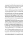
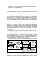
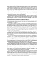
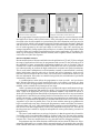
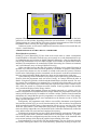
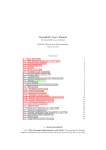
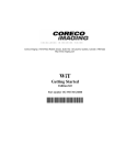
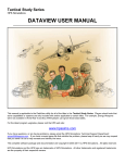
Presented at the 5th International Symposium on Robotics and Manufacturing, Aug. 15-17, 1994,
Maui, Hawaii.
USING HYPERMEDIA AND RECONFIGURABLE
SOFTWARE ASSEMBLY TO SUPPORT VIRTUAL
LABORATORIES AND FACTORIES
Matthew W. Gertz, David B. Stewart, Brad J. Nelson,
and Pradeep K. Khosla
Department of Electrical and Computer Engineering
The Robotics Institute at Carnegie Mellon University
Pittsburgh, Pennsylvania 15213
ABSTRACT
Recent developments in reusable and reconfigurable real-time software
make it possible to create virtual laboratories wherein applications for a
sensor-based system located at a particular location can be created by
assembling software modules designed at other sites, and executed in combination upon a robotic system at yet another site. Ultimately, such systems will lead to the development of virtual factories, wherein assembly
can be performed remotely, using network-accessible time-shared facilities, from sites which otherwise would lack the necessary resources to
accomplish such tasks. The benefits of these virtual laboratories and factories can be greatly enhanced by using hypermedia mechanisms. We have
developed Onika, an iconically programmed human-machine interface
with hypermedia capabilities, which interacts with reconfigurable software to assemble reusable code into applications. Onika can retrieve and
use software modules created at other sites via hyperlinks, integrating them
with modules created locally. Onika has been fully integrated with the Chimera real-time operating system in order to control several different
robotic systems at Carnegie Mellon University, both locally and remotely.
INTRODUCTION
Transfer and reuse of real-time application software is difficult and often seemingly impossible
due to the incompatibility between hardware and systems software at different sites. This has
meant that new technology developed at one site must be “reinvented” at other sites, if in fact
it can be incorporated at all. Technology transfer, therefore, has been a very expensive
endeavor. With the advent of structured software frameworks, such as the one given in [3][13],
differences in systems and code can be eliminated, leading to greater compatibility between
sites. However, a lack of resources at a site can still lead to an inability to incorporate new ideas
and technologies. To alleviate these problems, we propose the development of virtual laboratories to make both software and hardware readily accessible to researchers across networks
such as the Internet or the World-Wide Web. Resources for use in virtual laboratories would
be accessed by using hypermedia mechanisms [6][5].
We define the virtual laboratory as having the following qualities:
Distributed software libraries: Reconfigurable real-time software modules are stored in
object databases at various sites on the network. By using hyperlinks, retrieval of the software is transparent to the user regardless of its location.
Hardware resources: Various sensor-based systems are accessible via the network on a timeshare basis, so that a multitude of sites have access to equipment otherwise unavailable.
Interface: Each site wishing to use the shared software and hardware resources has a programming environment with hypermedia capabilities, and which can integrate code from
the distributed software libraries by searching through a global index and display realtime feedback from the sensor-based system on a multimedia workstation.
The advantages of a virtual laboratory include:
Increased technology transfer: Software developed and debugged at one site can be stored in
a software library, making it immediately available to other sites.
Zero logical distance: The interface to a virtual laboratory need not be running on the same
machine, nor even on the same filesystem, as their communications are all via hyperlinks
across a network. The interface may be running on a machine across the room, or on
another continent, without diminishing its ability to control a sensor-based system. Programmers intimately familiar with their interface need not modify it to control any remote
systems.
Expandability: New hardware (remote or local) can be integrated into the system and controlled quickly. This can be done by replacing or adding a software module to an existing
application, and leaving the rest of the modules in the application untouched.
Transparent simulation: Using reconfigurable software modules, any sensor-based real-time
program can be simulated without changing any of the real-time code, as each hardware
module has its simulated equivalent readily available in a software library.
Reduced costs: If a participating site wishes to expand on the research of another site, but
lacks the proper equipment, they can make use of the hardware resources available at a
cost substantially lower than purchasing the equipment themselves. Furthermore, the site
need not waste valuable time and money redeveloping code, since it would be available
in one of the software libraries.
Some of the problems which must be overcome include:
Software and hardware incompatibility: This has been the traditional curtailing technology
transfer in the past. Users wishing to use new technologies have often had to purchase
(and spend time setting up) entirely new hardware and operating systems, or else undertake the tedious task of translating code from one system to another.
Systems integration: To take advantage of shared software, the different jobs necessary to
complete an application must be integrated in such a way that routines common to more
than one job need only have one instantiation. Most real-time operating systems do not
support such capabilities, leaving those often-used functions to the application programmer, who must develop results in application-specific modules instead of reusable library
modules.
Lack of remote access to sensor-based systems: Most laboratories are not geared towards
controlling and monitoring sensor-based systems remotely.
Programming interface: Textual code can be difficult to interpret, moreso if it is ill-commented. The functionality of such software retrieved from remote sites is thus unclear,
limiting its use. Furthermore, controlling and monitoring the many parallel activities
which make up a single job is an difficult task when done from a command line interpreter.
To address these problems, the Advanced Manipulators Laboratory has developed Onika, an
iconic programming and control environment with hypermedia support[2][3][4], and Chimera,
a real-time operating system [11][12] supporting reconfigurable reusable real-time software
[13]. Whereas there have been other iconic interfaces for programming developed in the past
[8][1][7], Onika is currently the only such package which supports reconfigurable software
and hypermedia capabilities. The combined use of iconic programming and reusable software
has yielded the following benefits:
Software assembly: Reusable software modules downloaded from other sites can be immediately assembled with Chimera, despite any local differences in naming or programming
conventions. This capability has reduced our time to get new sensor-based systems online from weeks to hours.
Reconfigurability: Using reconfigurable software, systems integration is no longer a program. The software modules are independent of application, and can be used in a variety
of jobs.
Retrieval via hyperlinks: Onika has the ability to retrieve and automatically link software
modules from remote libraries into a Chimera executable.
Iconically programmed: Onika uses a novel program visualization mechanism, in which the
reconfigurable software modules available in the libraries are displayed as icons having
the appropriate input and output ports according to their underlying real-time port-based
objects model. The functionality of the modules is made clear to the user without resorting
to cryptic and ill-commented textual code. Icons can then be connected together graphically (and automatically) to form jobs. These jobs can immediately be run on Chimera
without having to write any “glue” code to integrate the modules. The state of the system
is made clear by viewing the application as a structured collection of icons in an “assembly window,” and by viewing running feedback transmitted from Chimera and displayed
in a separate “status” window within Onika.
In the following section, we discuss and give an example of reconfigurable real-time software.
RECONFIGURABLE AND REUSABLE SOFTWARE
This section is intended to give an overview of the framework for developing reconfigurable
and reusable software, which is supported by Chimera and Onika.
The lowest level of code normally accessible to an Onika user within our software framework is the control module, which is a self-contained port-based object having a certain
number of input ports and output ports [13]. The control module (or task; the two are used
interchangeably) may be periodic or aperiodic, and performs functions which are either realtime(e.g. compute torque from force) or non-real-time (e.g. log data to file). When combined
into a configuration, a set of concurrently-executing control modules performs some job (e.g.
move to point x). These jobs can further be combined in sequence to form a series of steps
forming a subsystem. An application is defined as one or more subsystems executing in parallel to perform some high-level mission. An application may be composed of other applications,
allowing for hierarchical decomposition of an application.
To integrate control modules into a configuration, a state variable table is used for realtime intertask communication [10]. The global state variable table stored in shared memory
contains the union of all of the input and output port variables of all the available modules.
Each task has its own local copy of the table, in which the variables actually used by the task
are kept current. The required input variables are transferred from the global table to the local
table at the beginning of a task’s cycle, and output variables are transferred from the local table
to the global table at the end of a task’s cycle. Each cycling task is “unaware” of the existence
of other tasks, since all communication is via the state variables tables. Thus, each task is selfcontained and generic, with its communication paths automatically updated when a subsystem
is reconfigured.
The generic nature of each task within a job allows us to quickly reconfigure into a subsequent job, reusing tasks common to both jobs. The change in configurations can be done either
statically or dynamically [10]. Static reconfiguration is primarily performed during the development of a job’s configuration, where only the tasks needed by the job are created on Chimera. This may involve trying and rejecting certain tasks in favor of others, during the design
process. Dynamic reconfiguration, on the other hand, is primarily seen during the transition
from one job to the next in an application. The union of all tasks needed for the entire application are created on Chimera at initialization, and simply activated and deactivated as required.
Dynamic reconfiguration can be performed without any loss of cycles.
An example of dynamic reconfiguration: Assume we have an application in which a PID
joint-motion job for a PUMA 560 (shown in Figure.1) is currently running on Chimera, and
τg
.
θr
PUMA
hardware
module
differentiator
module
DH
DOF
θm
θr
gravity
compensation
module
joint
trajectory
module
.
θr
θr
PUMA
hardware
module
differentiator
module
inverse
kinematics
DH
DOF
θm
τg
gravity
compensation
module
Cartesian
trajectory
module
forward
kinematics
xr
xm
Figure 1. A configuration controlling a PUMA in joint space. Figure 2. A configuration controlling an actual PUMA in
Cartesian space. The shaded tasks are those that remain from
the configuration in Figure 1 after reconfiguration.
the next job in line is a Cartesian-motion program (shown in Figure 2). The joint job consists
of the PUMA PID module, a gravity compensation module, a differentiator, a joint trajectory
module, and a display module (which reads in current joint values and sends them via a socket
to an external CAD program which displays the simulated robot on a screen). The Cartesian
job also contains the PUMA PID module, the gravity compensator, the differentiator, and the
display module. However, it does not contain the joint trajectory module. Instead, it contains
a Cartesian trajectory module, as well as forward kinematics, inverse kinematics, and a tool
module (which helps define the tool frame with respect to the end-effector). The union of the
tasks would have been created before the application was executed, but only the tasks involved
in the joint motion job would be cycling.
To reconfigure between the two jobs, the joint trajectory module is deactivated, and then
the forward and inverse kinematics modules, the Cartesian trajectory module, and the tool
module are activated. Note that neither the gravity compensation module, the PUMA PID
module, the differentiator module, nor the display module are affected in any manner; they
continue to cycle through the entire procedure, untouched.
Reconfiguring between two jobs by hand can be tedious, however. If the two configurations are very large, an inspection as to which modules should be deactivated and which should
be left running may be difficult. In the next section, we discuss how Onika, an iconic visual
programming environment, can be used to automate the process of reconfiguration.
A HYPERMEDIA ICONIC INTERFACE FOR RECONFIGURATION
In this section, we give a brief overview of Onika and an example of how it is used to control
reconfiguration within high-level applications. The reader who wishes more in-depth information should refer to [4] and [13].
When Onika is launched, it searches user preferences for hyperlink anchors to software
libraries. Remote libraries are downloaded and automatically linked with the local libraries
into a Chimera executable as needed. (If Onika is not located on the same file system as Chimera, the user can define a function to transfer the executable to Chimera’s machine.) An
iconic hyperlink is generated on-the-fly for each task, and is displayed to the user within a
library window. The user can retrieve a variety of information about any given task by clicking
on its icon, and can also modify the modules through this hyperlink (if allowable). The icon is
displayed as a port-based object, showing its input and output ports clearly, as well as its current status, its name, and its frequency.
Onika links with Chimera via a network, using two sockets. One socket is “read/write”,
and is used to issue commands to Chimera; acknowledgments or requests for more data are
returned from Chimera on the same socket. The other socket is “read-only,” and used by Chimera to send signals to Onika (these include error signals and special user-defined signals such
as “job completed”).
The user creates jobs by placing icons from the library onto a job canvas (which automatically spawns them on Chimera). The tasks automatically interconnect graphically with those
which share common data ports already placed into the configuration. The configurations are
thus assembled graphically, and can be saved for later recall. The individual tasks can be
turned on and off with simple mouse-clicks, and killed by selecting and deleting their icons.
Certain task parameters, such as frequency, can be changed easily, and aliases applied to I/O
ports which do not match the local naming conventions. A status window gives more detailed
information on the current status of real-time tasks and values of state variables.
Assuming that a configuration has been previously saved, reconfiguration into its job from
the current job can be achieved within Onika with a simple mouse-click. The user specifies the
configuration which should be loaded from a file navigator. The saved configuration contains
hyperlinks to the various modules it needs. Onika reads these in, and compares the links of the
two configurations. It then constructs the sequence of events necessary to dynamically reconfigure from the current job to the next. These instructions are sent to Chimera in the form of
command packets, and the real-time operating system reconfigures to the new job. Onika
checks Chimera’s reply to determine if the configuration was successful, and updates the job
canvas and the status information to reflect the current configuration.
As an actual example of reconfiguration using Onika, we use the configurations described
in Section 2. Figure 3 shows the Onika job canvas before reconfiguration, with the new configuration being selected. Figure 4 shows the resulting configuration, with the gravity compensator, the PUMA PID module, the differentiator, and the display module running during the
entire reconfiguration. Note that the user chose not to have the new tasks automatically activated after reconfiguration, and chose to have Onika completely kill tasks no longer used, demonstrating the various degrees of control available within the interface.
Figure 3. The PUMA joint-control configuration,
spawned on Chimera using Onika.
Figure 4. The current set of tasks after Onika dynamically
reconfigures to the PUMA Cartesian motion job.
The programmer can create a pictorial iconic hyperlink to the job, which can then be stored
in a higher-level library called a job dictionary. If the job requires some user input for execution (such as the desired endpoint in a joint motion job), this information can be pre-saved in
a user I/O object, which is also assigned a pictorial icon and stored in the dictionary. Both jobs
and objects can be viewed or edited by clicking on these pictorial anchors. Syntax and semantics are made apparent by the color and shape of each icon’s edges. Jobs and objects are
arranged sequentially, fitting together like puzzle pieces, in order to form an application. When
executed, Onika uses dynamic reconfiguration to traverse the application. A job which is finished (e.g. the trajectory endpoint has been reached) sends a signal to Onika, which then proceeds to the next job in the sequence.
RECENT MODIFICATIONS
Recent modifications to Chimera and Onika since the publication of [3] and [13] have enlarged
the range of applications which may be programmed and executed, to the point where all of
the capabilities of more conventional programming methods are met or exceeded. Tasks in
Chimera now contain a reinitialization routine, which allows the user to repeat task initialization without needing to perform the high-overhead task recreation and symbol translations.
This is useful when a manipulator’s tool information, normally a constant which is read only
during initialization, changes; tasks such as forward and inverse kinematics, which need to
know the current location of the tool frame, can execute their reinitialization routines to get
this new information. If the tasks are controlled using Onika, this reinitialization is performed
automatically when needed.
A synchronization routine allows the programmer to create aperiodic and synchronous
tasks. Instead of blocking on a clock interrupt before the cycle routine is executed, as is done
with periodic tasks, the programmer can set up the task to use some alternate synchronization
methods, such as external device interrupts or user input.
Onika’s grammar at the application level now includes both top test and bottom test loops,
case statements, breakpoints, and parallel flow ability. For loops and case statements, the “finished” signal of the appropriate job is used to determine whether a loop should be exited, or
which case line the application should follow. Breakpoints allow the user to stop and examine
the application’s state before proceeding. Parallel execution allows two or more subsystems to
operate concurrently, so that applications involving cooperation between manipulators can be
developed. A synchronization mechanism is included which allows the user to assign similar
“tagnames” to job icons in parallel flows. Two job icons with the same tag are guaranteed to
begin execution at the same time, allowing the programmer to make certain that (for instance)
one manipulator will “wait” while another manipulator completes certain preliminaries. At any
time, the user can abort an application, or force it to jump to the next job in line. The status of
the subsystems and variables is displayed and updated at various points during execution of
the application.
The icon of a task module acts as an hyperlink anchor, in that the textual code of a module,
if available, can be viewed and edited simply by clicking its task icon. The state of the memory
(i.e. corrupted or not) on the CPUs on which the tasks are cycling can also be determined with
a mouse click. These two modifications are very powerful tools for debugging modules.
Programmers may also define functions within Onika, and save them for future use. If programmers find that they use a certain display program frequently (for example), they can easily
create a button which acts as a link to a series of system commands which initialize the display
Figure 4. Part of the virtual laboratory display as shown to the Onika programmer.
program. When pressed, the host workstation executes these commands either in the background or in its own window, depending on how the user has defined it. U-Graph, a graphing/
plotting package at Carnegie Mellon University, has been incorporated into Onika using this
mechanism to allow users to plot output logged from their sessions.
In the next section, we discuss how Onika and Chimera have been used to research the concept of a virtual laboratory.
A DEMONSTRATION OF THE VIRTUAL LABORATORY
Shared hardware resources
Onika[3][13] and Chimera[10][13] have been used several times to control a manipulator
located hundreds of kilometers from the user, most recently in several demonstrations to toplevel administrators and scientists at Sandia National Laboratories. A Sun 4 workstation running X11R5 with Internet access was made available to us at Sandia, on which Onika could be
launched. The manipulator to be controlled (a PUMA 560 running in a Chimera environment)
was 2,600 kilometers away at Carnegie Mellon University.
Onika can either be run on the same file system as Chimera, or on a remote filesystem. In
the latter case, Onika runs faster, but must upload any executables it compiles to the Chimera
file system. In the former case, the executable is created on the same file system as Chimera,
but the entire Onika display must be transmitted over the network to the host workstation (in
this case located at Sandia). Both schemes have been used in remote demos in the past.
Upon launching, Onika searched the user preferences and found two hyperlink anchors to
libraries which the programmer used, one located “locally” at Carnegie Mellon, the other at
Sandia. Using these hyperlinks, Onika downloaded both libraries from the network. For security reasons, the programmer was prompted for a password before being able to access the
Sandia library. Once downloaded, Onika linked the required modules into a Chimera executable, which was stored in a Chimera-accessible location. Iconic hyperlinks to the modules
were created and displayed in the library window.
The programmer then launched Chimera, and Onika connected to it with the click of a
button. Using modules from both Sandia and Carnegie Mellon, the programmer created a joint
motion job and activated all of its modules in less than a minute. Cameras located around the
manipulator at Carnegie Mellon gave the programmer several different views of the manipulator, as 128x128 greyscale images were transmitted over the Internet at a rate of 10 Hz. The
setup is pictured in Figure 5.
Subsequently, the programmer used Onika to successfully demonstrate reconfiguration
into (and the execution of) a pre-saved Cartesian motion job, and execution of an application
which assembled a small DC motor. A demonstration of error recovery was also given, during
which the “panic button” of the manipulator was pressed, interrupting a joint trajectory. Chimera successfully trapped the error, and notified Onika. Onika then automatically cleared the
error, and the robot was reactivated and completed its trajectory.
Simulation of an application was successfully demonstrated by replacing the PUMA modules in an application with a simulation module and re-executing the same code. A synchronous module within the configurations passed the current joint values of the simulated robot
to an external package which displayed graphical representation of the robot.
Semi-autonomous visual servoing was also demonstrated. The user clicked on a point in
the window showing the camera view of the laboratory, dynamically creating an object con-
taining the location of that point in the vision plane. The manipulator then immediately moved
to the point specified by that object.
Throughout the demonstration, complete control was assumed at Sandia. Researchers on
location at Carnegie Mellon were available to “power up” the robot when needed (a necessary
safety precaution during these experimental demonstrations) and to intercede if the robot
showed signs of instability in this experimental set-up, but otherwise did not interfere with the
demo in any manner.
Shared software resources
The nature of the generic software modules in our laboratory’s libraries is such that most of
the code required to get new systems operating is already available. Using Onika and Chimera
to assemble and control these modules, a previously-unused mobile robot (left over from a
graduate student’s project several years previous) was brought on line and visual servoing programs executed on it in less than two days. The only module which needed to be created for
the mobile manipulator was the one that actually communicated with the robot’s hardware;
other modules, such as trajectory, kinematics, and visual servoing modules, were already available. A Utah-MIT hand located in our laboratory has also been brought on line in the same
fashion, and no less than six other systems (including two Adept robots, two American robots,
a Stewart platform, and the Reconfigurable Modular Manipulator System [9]) either have been
or will be brought on line over the next several months, bringing a total of eleven systems
under shared software control in our laboratory.
Technology transfer
The software libraries at Carnegie Mellon were recently used to launch new robotic systems at
the Air Force Logistics Center (AFLC) in Texas. AFLC obtained the Chimera and Onika software and, using the software libraries, was able to get its systems up and running in less then
two days. As enhancements to the Chimera real-time operating system and to the task modules
have been made, WPAFB has been able to download and immediately use these upgrades.
Other laboratories are currently in the process of obtaining the Chimera and Onika packages
as well. As these sites do research using the reconfigurable software framework for reusable
software modules, the task libraries available throughout the user community continues to
grow.
FUTURE WORK
In the coming months, we plan on refining the user interface, and increasing Onika’s abilities
to retrieve and use shared software. Formal human factors testing on the Onika interface is set
to begin in the near future. Onika is currently in beta-test at NIST, and will be distributed to
several other sites which use Chimera. Informal testing has shown that new users can learn
how to program and control modules and jobs from Onika in less than an hour, and that the
time required for programmers to assemble existing modules and jobs into a desired application is significantly less than that of conventional testing methods.
In order for virtual laboratories to become a reality, the following must be addressed:
Real-time networking: Currently, we experience a delay of five to ten seconds when controlling a CMU robot from Sandia, since the Internet is not a real-time network. Such a delay
is unacceptable in many cases. Faster lines and better routing algorithms need to be developed, and will be, as the super-information highway begins to take shape.
Dynamic linking of modules: Currently, modules must be linked into an “executable” before
they can be used in Chimera. This means that required modules must be downloaded
before Chimera begins executing, rather than during a Chimera session. Dynamic linking
would allow users to add libraries and modules during a session.
Selective software sharing: Because of slow network times and static linking, remote libraries are generally completely downloaded, with the remote connection to the library then
terminated to keep Onika from blocking on long network delays. It would be better to not
download the actual code until the icon of a remote module was actually placed into a configuration, thus forming a true distributed software library. We are currently developing a
version of Onika with enhanced hypermedia mechanisms to access and retrieve specific
shared software modules on the fly, rather than at system initialization.
Enhancing simulation capabilities: Currently, our real-time simulations only address the
objects being controlled. Future real-time simulations will need to include other objects
and obstacles in the manipulator’s environment as well.
Our future research is directed towards making dynamic linking of modules and selective software sharing a priority, so as to make virtual laboratories and factories a reality.
CONCLUSION
In the future, virtual laboratories will be a powerful tool in sensor-based systems research,
leading to the development of “virtual factories” to aid in manufacturing. Access to hardware
and software will no longer be a limiting factor in determining what research can be pursued,
and what new technology can be implemented. Although more research and development is
required before this scenario can become a reality, an important starting point towards building
these laboratories along the “super-information highway” is the adoption of a software framework which accommodates reusable and reconfigurable software modules, as well as an interface for retrieving and controlling the modules so that the shared resources can be easily used.
ACKNOWLEDGEMENTS
The research in this paper is supported, in part, by Sandia National Laboratories, NASA, and
the Dept. of Electrical and Computer Engineering and The Robotics Institute at Carnegie
Mellon University. Partial funding for Matthew W. Gertz is provided by NASA Langley
Research Center through a GSRP fellowship. Partial funding for David B. Stewart is provided
by the Natural Sciences and Engineering Research Council of Canada (NSERC) through a
graduate fellowship. The authors would like to thank Sandia National Laboratories and AFLC
for their cooperation, and Wayne Carriker, Dan Morrow, Darin Ingimarson and Richard
Voyles of the Advanced Manipulators Laboratory for their participation in demonstrations,
their software contributions to the virtual laboratory development process, and for putting up
with constant revisions during the alpha-test stage. More information on Chimera and Onika
may be obtained by e-mailing requests to [email protected].
REFERENCES
[1]Chang, S. K. “Visual Languages: A Tutorial and Survey,” IEEE Software, January 1987, pp. 29-39.
[2]Gertz, M.W., Stewart, D. B., and Khosla, P. K. “An Iconic Language for Sensor-Based Robots,” in
Proceedings of SOAR Conference, August 4-6, 1992, Houston, Texas.
[3]Gertz, M.W., Stewart, D. B., and Khosla, P. K. “A Software Architecture-Based Human-Machine Interface for Reconfigurable Sensor-Based Control Systems,” in Proceedings of 8th IEEE International Symposium on Intelligent Control, Aug. 25-26, 1993, Chicago, Ill.
[4]Gertz, M.W. and Khosla, P. K. “The Onika User’s Manual,” Program Documentation, Dept. of Elec.
and Comp. Engineering and The Robotics Institute, Carnegie Mellon University, Pittsburgh, PA
15213 (e-mail [email protected] for a copy).
[5]Grøenbæk, K., and Trigg, R.H. “Design Issues for a Dexter-Based Hypermedia System,” Communications of the ACM, Vol. 37, No. 2, pp. 40-49, February 1994.
[6]Halasz, F., and Schwartz, M. “The Dexter Hypertext Reference Model: Hypermedia,” Communications of the ACM, Vol. 37, No. 2, pp. 30-39, February 1994.
[7] Leifer, L., Van der Loos, M., and Lees, D. “Visual Language Programming: for robot command-control in unstructured environments,” Proceedings of the Fifth International Conference on Advanced
Robotics: Robots in Unstructured Environments, June 19-22, 1991, pp. 31-36, Pisa, Italy.
[8] Myers, B. A. “Taxonomies of Visual Programming and Program Visualization,” Journal of Visual
Languages and Computing, 1990 (1), pp. 97-123.
[9]Schmitz, D.E., Khosla, P.K., and Kanade, T. “The CMU reconfigurable modular manipulator system,” in Proceedings of the International Symposium and Exposition and Exposition on Robots
(designated 19th ISIR), Sydney, Australia, pp. 473-488, November 1988.
[10]Stewart, D. B., Volpe, R. A., and Khosla, P. K. “Integration of software modules for reconfigurable
sensor-based control systems,” in Proceedings of 1992 IEEE/RSJ International Conference on Intelligent Robots and Systems (IROS ‘92), Raleigh, North Carolina, July 1992.
[11]Stewart, D. B. and Khosla, P. K. Chimera 3.0 Real-Time Programming Environment, Program Documentation, Dept. of Elec. and Comp. Engineering and The Robotics Institute, Carnegie Mellon
University, Pittsburgh, PA 15213 (e-mail [email protected] for a copy).
[12]Stewart, D. B., Schmitz, D. E., and Khosla, P. K. “The Chimera II real-time operating system for
advanced sensor-based robotic applications,” IEEE Transactions on Systems, Man, and Cybernetics, vol. 22, no. 6, pp. 1282-1295, November/December 1992.
[13]Stewart, D. B., Volpe, R. A., and Khosla, P. K. “Design of Dynamically Reconfigurable Real-Time
Software using Port-Based Objects,” Technical Report CMU-RI-TR-93-11, Dept. of Elec. and
Comp. Engineering and The Robotics Institute, Carnegie Mellon University, Pittsburgh, PA 15213.