1
GE Fanuc Automation
Programmable Control Products
TCP/IP Ethernet Communications
for the Series 90™ PLC
User's Manual
GFK-1541B
May 2002
GFL-002
Warnings, Cautions, and Notes
as Used in this Publication
Warning
Warning notices are used in this publication to emphasize that hazardous voltages,
currents, temperatures, or other conditions that could cause personal injury exist in this
equipment or may be associated with its use.
In situations where inattention could cause either personal injury or damage to
equipment, a Warning notice is used.
Caution
Caution notices are used where equipment might be damaged if care is not taken.
Note
Notes merely call attention to information that is especially significant to understanding and
operating the equipment.
This document is based on information available at the time of its publication. While efforts
have been made to be accurate, the information contained herein does not purport to cover all
details or variations in hardware or software, nor to provide for every possible contingency in
connection with installation, operation, or maintenance. Features may be described herein
which are not present in all hardware and software systems. GE Fanuc Automation assumes no
obligation of notice to holders of this document with respect to changes subsequently made.
GE Fanuc Automation makes no representation or warranty, expressed, implied, or statutory
with respect to, and assumes no responsibility for the accuracy, completeness, sufficiency, or
usefulness of the information contained herein. No warranties of merchantability or fitness for
purpose shall apply.
The following are trademarks of GE Fanuc Automation North America, Inc.
Alarm Master
CIMPLICITY
CIMPLICITY 90–ADS
CIMSTAR
Field Control
GEnet
Genius
Helpmate
Logicmaster
Modelmaster
Motion Mate
PowerMotion
PowerTRAC
ProLoop
PROMACRO
Series Five
Series 90
Series One
©Copyright 2002 GE Fanuc Automation North America, Inc.
All Rights Reserved.
Series Six
Series Three
VersaMax
VersaPoint
VersaPro
VuMaster
Workmaster
Contents
Chapter 1
Introduction .........................................................................................................1-1
The Ethernet Interface....................................................................................................... 1-2
Ethernet Interface Ports..................................................................................................... 1-4
The Station Manager Software ......................................................................................... 1-7
Chapter 2
Installation ...........................................................................................................2-1
Installing an IC693CMM321 Ethernet Interface Module................................................. 2-2
Installing an IC693CPU364 with Embedded TCP/IP Ethernet Interface ....................... 2-16
Installing an IC693 CPU374 with Embedded TCP/IP Ethernet Interface ...................... 2-30
Installing the IC697CMM742 Ethernet Interface ........................................................... 2-41
Chapter 3
Programming SRTP Channel Commands........................................................3-1
The Communications Request .......................................................................................... 3-2
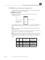
COMMREQ Function Block and Command Block ......................................................... 3-6
Channel Commands .......................................................................................................... 3-9
Status Data ...................................................................................................................... 3-31
Controlling Communications in the Ladder Program..................................................... 3-43
Chapter 4
Programming Modbus/TCP Channel Commands ...........................................4-1
The Communications Request .......................................................................................... 4-2
COMMREQ Function Block and Command Block ......................................................... 4-5
Modbus TCP Channel Commands.................................................................................... 4-8
Status Data ...................................................................................................................... 4-20
Controlling Communications in the Ladder Program..................................................... 4-26
Chapter 5
Ethernet Global Data ..........................................................................................5-1
Overview of EGD ............................................................................................................. 5-2
Configuring EGD............................................................................................................ 5-12
Adapter Names, Aliases, and Groups ............................................................................. 5-21
Exchange Status Word.................................................................................................... 5-23
Simple Network Time Protocol (SNTP)......................................................................... 5-25
Chapter 6
Network Administration Support......................................................................6-1
IP Addressing.................................................................................................................... 6-2
Gateways........................................................................................................................... 6-4
Subnets and Multiple Gateways........................................................................................ 6-5
Configuring Multiple Gateways........................................................................................ 6-7
Network Address Naming Architecture............................................................................ 6-9
GFK-1541B
iii
Contents
Chapter 7
Troubleshooting...................................................................................................7-1
Diagnostic Tools Available for Troubleshooting.............................................................. 7-2
What to do if you Cannot Solve the Problem ................................................................... 7-3
PLC Fault Table................................................................................................................ 7-4
Appendix A
Glossary ............................................................................................................... A-1
Appendix B
Communications Port Characteristics ............................................................. B-1
RS-232, RJ-11 Serial Port................................................................................................ B-2
RS-485, 15-Pin, D-Type Port........................................................................................... B-4
10Base-T Port .................................................................................................................. B-6
10Base-T/100Base Tx Port .............................................................................................. B-8
10Base2 Port .................................................................................................................. B-11
AAUI Port...................................................................................................................... B-13
AUI Port......................................................................................................................... B-19
Appendix C
PC Software Loader ........................................................................................... C-1
Updating Firmware Under Windows............................................................................... C-2
Updating Firmware Under DOS and Windows 3.xx ....................................................... C-4
Appendix D
Using the IC697CMM742 with PLC CPU Versions 4.12 - 5.50 ..................... D-1
Ethernet Interface Operational Restrictions..................................................................... D-6
Appendix E
iv
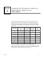
Translating PLC CPU Reference Addresses to Modbus Register Addresses
for the IC693CMM321....................................................................................... E-1
TCP/IP Ethernet Communications for the Series 90™ PLC User's Manual– May 2002
GFK-1541B
Contents
GFK-1541B
Contents
v
Chapter
Introduction
1
This manual describes the following Ethernet Interfaces for the Series 90 PLC:
Series 90-30 PLC TCP/IP Ethernet Interface (IC693CMM321)
Series 90-30 PLC CPU364 with embedded TCP/IP Ethernet Interface (IC693CPU364)
Series 90-30 PLC CPU374 with embedded TCP/IP Ethernet Interface (IC693CPU374)
Series 90-70 PLC TCP/IP Ethernet Interface (Type 2) (IC697CMM742)
The general term, Ethernet Interface, will be used in this manual except when differences in the
Interfaces require the more specific terms.
The Series 90-30 PLC CPU 364 and CPU374 are both modules that contain a PLC CPU and an
embedded Ethernet Interface. The general term Embedded Ethernet Interface will be used in this
manual to refer to these modules.
This chapter provides an overview of the Ethernet Interface and covers the following topics:
GFK-1541B
The Ethernet Interface
How to Make the System Work
Quick Guide to the Manual
1-1
1
The Ethernet Interface
The Ethernet Interface enables Series 90 PLCs to communicate with other Series 90 PLCs, with
with GE Fanuc PLC programming software, and with applications developed using the SRTP
protocol, such as CIMPLICITY® HMI.
The Ethernet Interfaces described in this manual have “client/server” capability. As a “client” the
Interfaces can initiate communications with other Series 90 PLCs containing Ethernet Interfaces.
This is done from the PLC ladder program using the COMMREQ function. As a “server” the
Interfaces respond to requests from other devices such as PLC programming software, a Host
computer running an SRTP application, or another Series 90 PLC acting as a “client”. No PLC
programming is required for server operation.
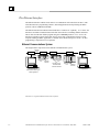
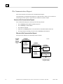
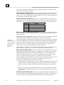
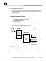
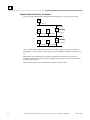
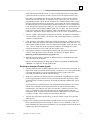
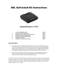
Ethernet Communications System
The diagram below represents a basic Ethernet Communications system.
Ethernet
Cable
Transceiver
Transceiver
Transceiver
Transceiver
Network
Connection
Series 90-30
Ethernet
PLC
Interface
Transceiver
Network
Connection
Series 90-30
PLC
CPU 364 or 374
with Embedded
Ethernet Interface
Series 90-70
Ethernet
PLC
Interface
Host Computer or
Control Device Running an
SRTP Application
Programmer
® Windows is a registered trademark of Microsoft Corporation.
1-2
TCP/IP Ethernet Communications for the Series 90™ PLC User's Manual – May 2002
GFK-1541B
1
Capabilities of the Ethernet Interface
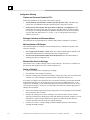
The Ethernet Interface brings to your PLC a great deal of capability. It will allow you to:
Become operational quickly. The Ethernet Interface is made operational with very little effort.
You need only install the Interface in the PLC rack or baseplate and use the PLC
programming software to store basic configuration information to the module to make the
basic SRTP server capability functional. SRTP Client capability, the capability to initiate
communications, can be added using the COMMREQ function in the ladder program. For
Series 90-30 Ethernet Interface IC693CMM321-FH and later, basic Modbus/TCP server
capability is available as soon you supply basic configuration information to the module, and
you can use COMMREQs to initiate Modbus/TCP communications.
Directly attach your PLC to an Ethernet network. The Ethernet Interface allows you to directly
attach the Series 90 PLC to an Ethernet LAN via the built-in network ports or via a usersupplied transceiver and AUI or AAUI cable, and to communicate with host computers and
other Series 90 PLCs on the local network.
Ethernet Global Data. (Series 90-30 CPU364 and CPU374 and Series 90-70 Ethernet
Interface (Type 2) only.) When used with the latest Series 90 CPUs, the Ethernet Interface
provides highly efficient periodic data transfer between PLCs using Ethernet Global Data
exchanges.
Transfer data between PLCs. The Ethernet Interface provides client capability, the capability
to initiate communications to other Series 90 Ethernet Interfaces, using COMMREQ
functions in the ladder program.
Access data using a Host computer. Computer applications which use the SRTP protocol can
access data within the Series 90 PLC through the server capability of the Ethernet Interface. .
Communicate simultaneously to multiple devices. The multiplexing capabilities of the
Ethernet Interface, along with Ethernet network’s high capacity, allow the PLC to
communicate with several other devices at the same time.
Maintain compatibility with other GE Fanuc devices and devices from other vendors. The
Series 90-30 Ethernet Interface, Series 90-30 CPU364 Embedded Ethernet Interface, Series
90-30 CPU374 Embedded Ethernet Interface, and Series 90-70 Ethernet Interface (Type 2)
are compatible with each other. They are also compatible with GE Fanuc programming
packages supporting TCP/IP Ethernet communications.
Diagnose and maintain your system, using diagnostic and station management tools. You can
find problems before they become serious. In the event that communications software
upgrades are needed, you can use a built-in serial port to download the software to the
Ethernet Interface.
Indirectly attach to other Local Area Networks and/or wide area networks via third party IP
routers. When configured to use an IP gateway (router), the Ethernet Interface can
communicate with remote PLCs and other nodes reachable through the router.
Communicate with remote computers via Serial Line Protocol (SLIP) using modems and/or
serial lines. Using third party SLIP software, a remote host computer can be attached to a
TCP/IP network.
Communicate with other Series 90 PLCs using symbolic names as well as IP addresses.
COMMREQs can be programmed to communicate with PLCs using IP addresses or Network
Address names (Series 90-30 Ethernet Interface, Series 90-30 CPU364 Embedded Ethernet
Interface, and Series 90-70 Ethernet Interface (Type 2)).
®Windows and Windows NT are registered trademarks of Microsoft Corporation.
GFK-1541B
Chapter 1 Introduction
1-3
1
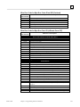
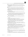
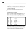
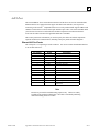
Ethernet Interface Ports
The Ethernet Interfaces provide ports for connection to the Ethernet network as listed below.
IC693CMM321 Series 90-30 TCP/IP
Ethernet Interface
IC693CPU364 Series 90-30 CPU with
Embedded TCP/IP Ethernet Interface
IC693CPU374 Series 90-30 CPU with
Embedded TCP/IP Ethernet Interface
IC697CMM742 Series 90-70 TCP/IP
Ethernet Interface (Type 2)
AAUI Port
10Base-T Port (RJ-45) (Module version
FG or later)
AAUI Port
10Base-T Port (RJ-45)
Auto-sensing 10Base-T Port (RJ-45)
10Base-T Port (RJ-45)
AUI Port
10Base2 Port (BNC)
Port Descriptions
10Base-T, RJ-45 port (Series 90-30 Ethernet Interface (10Base-T Type), Series 90-30 CPU364,
and Series 90-70 IC697CMM742 Ethernet Interface (Type 2))
The 10Base-T port uses a twisted pair cable of up to 100 meters in length between each node and
a hub or repeater. Typical hubs or repeaters support 6 to 12 nodes connected in a star wiring
topology.
Auto-sensing 10 Base T / 100 Base TX, RJ-45 Port (Series 90-30 CPU374 only)
The auto-sensing 10 Base T / 100Base TX ports are connected to a switch device embedded in the
Ethernet Interface. They use a twisted pair cable (unshielded or shielded) of up to 100 meters in
length between the node and another node, a hub, a repeater, or a switch. The port automatically
senses the speed (10Mbps or 100Mbps), duplex mode (half duplex or full duplex) and cable
(straight-through or crossover) attached to it with no intervention required.
10Base2, BNC port (Series 90-70 Ethernet Interface (Type 2))
The 10Base2 port uses a 0.2 inch diameter 50-ohm coaxial cable and is commonly called “thin
wire”. The maximum length of a cable segment is 185 meters. A maximum of 30 stations is
allowed on a 10Base2 Ethernet segment.
AUI Port (Series 90-70 Ethernet Interface (Type 2)) and
AAUI Port (Series 90-30 Ethernet Interface (AAUI-only Type) and Series 90-30 CPU364)
The AUI and AAUI ports provide the electrical and mechanical interface to the user-provided
Ethernet transceiver cable, which connects the AUI or AAUI port to an external user-provided
transceiver. (The transceiver cable may be separate or built-in to the transceiver.) The external
transceiver is directly connected to the Ethernet cable.
1-4
TCP/IP Ethernet Communications for the Series 90™ PLC User's Manual – May 2002
GFK-1541B
1
Ethernet Media
Various Ethernet baseband media (10Base...) can be interconnected by appropriate hubs or
repeaters. Capabilities and limitations are defined in IEEE 802.3 Chapter 13, “System
Considerations for Multi-Segment Networks”. This document is published by the Institute of
Electrical and Electronics Engineers, Inc., 345 East 47th Street, New York, NY 10017-2394 USA.
The Ethernet Interface can operate on any of the following media with the appropriate usersupplied transceiver cable and transceiver. IEEE 802.3 specifies the definitive requirements of
each medium.
10Base5 Coax: 10Base5 uses a 0.4 inch diameter 50-ohm coaxial cable and is commonly called
“thick wire”. The maximum length of a cable segment is 500 meters. The distance between any
two stations must be a multiple of 2.5 meters. A maximum of 100 stations is allowed on a
10Base5 Ethernet segment.
10Base2 Coax: 10Base2 is described above.
10Base-T: 10Base-T is described above.
10Base-F: 10Base-F has two variations that both use the same type of fiber-optic cable.
10Base-FP can support up to 33 nodes at distances of up to 500 meters from a passive star;
10Base-FL supports up to 2000 meters between a node and a repeater (a multi-port repeater
would thus constitute a star). Additionally, 10Base-FB provides a means of interconnecting
(only) repeaters by up to 2000 meters of (the same) fiber-optic cable.
10Broad36: 10Broad36 uses 75-ohm coaxial cable and CATV-like media components (taps,
amplifiers, headend translators, etc.) to support hundreds of nodes at distances of up to 2800
meters. Broadband cannot be connected to baseband via repeaters. Broadband cable plant design
and installation must be in accordance with IEEE 802.7 and requires special expertise. GE Fanuc
recommends you contract professional specialists for these services. Consult your GE Fanuc
sales representative or field service office for help in identifying local specialists.
GFK-1541B
Chapter 1 Introduction
1-5
1
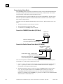
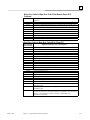
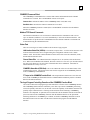
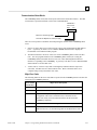
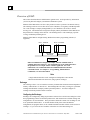
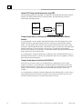
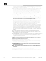
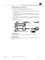
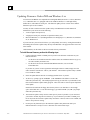
Special Considerations for Ethernet Interfaces with Embedded Switches
Ethernet Interfaces that incorporate embedded switches (only the Series 90-30 CPU374) provide
some additional connection options and have some additional installation and operation
considerations.
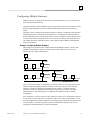
These Ethernet Interfaces provide two RJ-45 connectors on the front of the module. It is
important to realize that there is only one interface to the network (only one Ethernet address and
only one IP address) provided by these Ethernet Interfaces. The two connectors allow up to two
Ethernet devices (hubs, switches, other PLCs, PCs) to be connected to the Ethernet Interface. This
arrangement is diagrammed below.
90-30 CPU374
Ethernet
Processor
Ethernet
MAC
10/100 Network
Switch
Port 1
Port 2
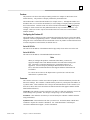
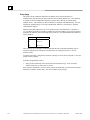
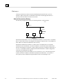
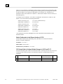
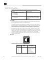
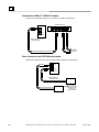
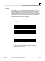
For simple installations, the embedded switch allows PLCs and other devices to be connected
together without requiring any additional components.
Operator
Interface
PLC
PLC
Personal
Computer
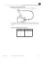
It is also possible to daisy-chain PLCs together without additional components, but that should be
done with great care. In designing a system, remember that a loss of power or reset on any
Ethernet Interface in a daisy chain will cause loss of communications with all devices
downstream from the lost module.
The second port, if left unused, can be used to plug in a programmer over Ethernet.
Caution
The two ports on the Ethernet Interface must not be connected, either directly or indirectly,
to the same device. The hub or switch connections in an Ethernet network must form a tree,
otherwise duplication of packets may result.
1-6
TCP/IP Ethernet Communications for the Series 90™ PLC User's Manual – May 2002
GFK-1541B
1
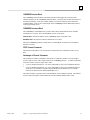
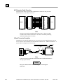
The Station Manager Software
The built-in Station Manager software provides on-line supervisory access to the Ethernet
Interface, through either the Station Manager port or over the Ethernet cable. The Station
Manager services on the Ethernet Interface include:
An interactive set of commands for interrogating and controlling the station.
Unrestricted access to observe internal statistics, an exception log, and configuration
parameters.
Password security for commands that change station parameters or operation.
Access to the Station Manager is attained through a user-provided computer terminal or terminal
emulator. See GFK-1186, TCP/IP Ethernet Communications for the Series 90 PLC Station
Manager Manual, for more information on the Station Manager.
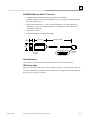
The PC Software Loader
The PC Software Loader is a separate software utility which runs on a PC in order to update the
communications software stored in flash memory in the Ethernet Interface. This utility is
supplied with any updates to the Ethernet Interface software.
How to Make the System Work
There are only a few simple tasks required to get your Ethernet communications system working.
These tasks are addressed in detail later in this manual.
GFK-1541B
1.
Install the Ethernet Interface into the Series 90 rack or baseplate and connect it to the
network.
2.
Power-up the PLC.
3.
Configure the Ethernet Interface using the PLC programming software and store to the PLC.
4.
To add optional SRTP client capability, refer to Chapter 3 “Programming SRTP Channel
Commands” . To add optional Modbus/TCP client capability (Series 90-30 Ethernet
Interface IC693CMM321-FH or later only), refer to Chapter 4 “Programming Modbus/TCP
Channel Commands”. To configure or program Ethernet Global Data, refer to Chapter 6,
“Ethernet Global Data”.
Chapter 1 Introduction
1-7
1
1-8
TCP/IP Ethernet Communications for the Series 90™ PLC User's Manual – May 2002
GFK-1541B
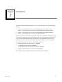
Chapter
Installation
2
This chapter contains installation instructions for each Series 90 module that includes an Ethernet
Interface.
Section 1: IC693CMM321 Series 90-30 TCP/IP Ethernet Interface (10Base-T type)
Section 2: IC693CPU364 Series 90-30 CPU with Embedded TCP/IP Ethernet Interface
Section 3: IC693CPU374 Series 90-30 CPU with Embedded TCP/IP Ethernet Interface
Section 4: IC697CMM742 Series 90-70 TCP/IP Ethernet Interface
Each section covers the basic features of the Ethernet Interface, its installation, configuration, and
a procedure for its initial checkout on your Ethernet cable. Each section first provides a hardware
overview of the Ethernet Interface and is then divided into four Installation Procedures, each
providing an overview of the procedure and then explaining the detailed steps to be performed.
The installation procedures described for each Ethernet Interface are:
Installing the Ethernet Interface in the PLC - Required
Configuring the Ethernet Interface - Required
Verifying Proper Power-Up of the Ethernet Interface - Required
“Pinging” the Ethernet Interfaces on the Network - Optional
Some of the procedures require prior Ethernet cable plant design and installation.
GFK-1541B
2-1
2
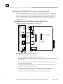
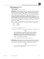
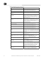
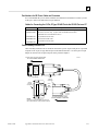
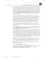
Installing an IC693CMM321 Ethernet Interface Module
The IC693CMM321Ethernet Interface mounts in a Series 90-30 PLC baseplate. It connects to an
Ethernet network either directly through its 10Base-T port (10Base-T Type only), or through its
AAUI port, which requires a user-provided transceiver and cable. If using the AAUI port, you
may order a transceiver from GE Fanuc (see Appendix B for information) or supply your own
equivalent transceiver. .
IC693CMM321 Series 90-30 TCP/IP Ethernet Interface (10Base-T Type)
CMM321 versions EF or earlier do not have a 10Base T port.
OK
CMM321
ETHERNET LAN
INTERFACE
FDX
STAT
ETHERNET
RESTART
STATION
MGR
RS-232
OK
LAN
FDX
STAT
RESTART
PUSHBUTTON
Serial Number
Label (Internal)
RS-232 STATION
MANAGER
PORT (RJ-11)
10BASE-T
10BASE-T
PORT (RJ-45)
Default Station
Address Label
(Internal)
AAUI PORT
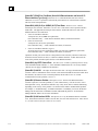
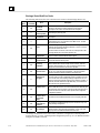
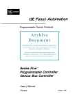
This module has several user-accessible features:
2-2
Four LEDs are located at the top of the board.
The Restart pushbutton is located immediately below the LEDs.
The Station Manager port (RS-232 serial port with an RJ-11 connector) is located on the front
of the module.
The 10Base-T Ethernet port (RJ-45 connector) is located on the front of the module. It does
not require an external transceiver.
The AAUI port (14-pin AAUI connector) is accessible through an opening in the bottom of
the module. It requires an external transceiver.
The Default Station Address label lists the MAC address to be used by this Interface. It is
located by removing the module’s front cover and looking on the circuit board.
The module’s serial number is on the silver label on the left side of the module.
TCP/IP Ethernet Communications for the Series 90™ PLC User's Manual – May 2002
GFK-1541B
2
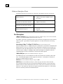
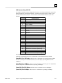
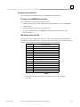
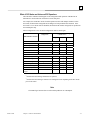
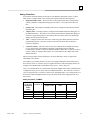
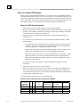
LEDs
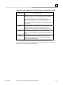
There are four LEDs on the CMM321 module. Each of these LEDs can be ON, OFF, or
BLINKING.
LED
Indication Function
OK
State of the Ethernet Interface
LAN
Traffic on the network port
FDX
Configuration of Full Duplex mode.
STAT
An exception event has occurred
All LEDs are briefly turned ON whenever a restart is performed in the Operational state by
pressing and releasing the Restart pushbutton (described below). This allows you to verify that all
LEDs are operational. (On module versions EF or earlier, the FDX LED is labeled "SER".)
Restart Pushbutton
The Restart pushbutton serves four functions: LED test, Restart, Restart and enter Software Load
state, and Restart and enter Maintenance state. These four functions behave similarly in all states
except for the Software Load state. While in this state, pressing the pushbutton will cause an
immediate restart into the Operational state (without performing the LED test) if the software in
the Ethernet Interface has not been corrupted or erased. If the software has been corrupted or
erased, pressing the pushbutton will cause an immediate restart back into the Software Load state.
The following text describes Restart pushbutton behavior while not in the Software Load state.
Pressing the Restart pushbutton will disrupt Ethernet communications.
LED Test: Any time the Restart pushbutton is released, all the LEDs flash ON. You should
visually verify that all the LEDs go OFF and then ON at this time. Then the Interface performs
either a restart, a restart and enter Software Load state, or a restart and enter Maintenance state,
depending on the duration that you press the pushbutton.
Restart: Pressing the Restart pushbutton momentarily (less than 5 seconds) requests a restart of
the Ethernet Interface. When the Restart pushbutton is pressed, all LEDs go out. When it is
released, all LEDs flash ON, then power-up diagnostics run, and the software on the Interface is
restarted into the Operational state.
GFK-1541B
Chapter 2 Installation
2-3
2
Restart and Enter Software Load State: Pressing and holding the Restart pushbutton until the
bottom LED (STAT) turns ON (between 5 and 10 seconds) forces a restart and requests entrance
to the Software Load state. A reload is used to install a software update into the module and is
not part of normal operation. When the Restart pushbutton is pressed, all LEDs go out. After
approximately 5 seconds have elapsed, the STAT LED (bottom LED) comes ON, to indicate that
the Ethernet Interface will request a reload. After the Restart pushbutton is released, all LEDs
flash ON, then power-up diagnostics run, and the Ethernet Interface waits for the software load
with all LEDs blinking in unison.
Notes
Reloading the Ethernet Interface requires the attachment of the PC Software
Loader to the Software Loader port and initiating a load with the PC Software
Loader. The PC Software Loader is a separate software utility that updates the
communications software in the Ethernet Interface. This utility is supplied with
any updates to the Ethernet Interface software.
At any time before you initiate a load with the PC Software Loader when the
Ethernet Interface is in the Software Load State, you can restart the Ethernet
Interface by pressing the Restart pushbutton. Pressing this pushbutton will
immediately cause the board to restart. If the reload has been initiated, see
Appendix C, “Upgrading the Ethernet Interface Firmware,” for more
information.
Restart and Enter Maintenance State: Pressing and holding the Restart pushbutton until the
bottom two LEDs turn ON (approximately 10 seconds) forces a restart and requests entrance to
the Maintenance state. Maintenance state must be invoked to change Advanced Parameters.
While in Maintenance state, all Advanced Parameters revert to their default value. When the
Restart pushbutton is pressed, all LEDs go out. After approximately 5 seconds, the STAT LED
comes ON, then after approximately a total of 10 seconds have elapsed, the FDX LED also comes
ON, to indicate that the Ethernet Interface will request entry to the Maintenance state. After the
Restart pushbutton is released, all LEDs flash ON then power-up diagnostics run and the Ethernet
Interface enters the Maintenance state.
Notes
If a Restart is performed, any data being transferred by the Ethernet Interface at
that time will be lost.
The Restart pushbutton is not operable during the diagnostic phase of power-up.
The Ethernet Interface is in diagnostic phase when the OK LED is BLINKING
fast and other LEDs are OFF.
2-4
TCP/IP Ethernet Communications for the Series 90™ PLC User's Manual – May 2002
GFK-1541B
2
Ports on the CMM321
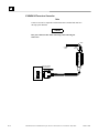
RS-232, RJ-11 Port (Station Manager Port)
The RS-232, 6-pin, RJ-11 “phone jack” port is used to connect a terminal or terminal emulator to
access the Station Manager software on the Ethernet Interface. A cable is needed to connect the
terminal or emulator to the Ethernet Interface (see Appendix B, “Communications Ports
Characteristics”). This port is also used to update the module’s firmware.
Ethernet Ports
The CMM321 has just one Ethernet interface. Connection to the Ethernet network can be made
either through the 10Base-T connector or the AAUI connector. You must connect to just one or
the other connector; you cannot use both at the same time. Note that module versions EF and
earlier do not have a 10Base T port, and can only be connected through their AAUI port.
10Base-T Port
This port is located on the front of the module and it can be directly connected to a 10Base-T
network (no external transceiver is needed). It uses a standard RJ-45 jack. See Appendix B for
port details.
AAUI (Transceiver) Port
This port uses a standard 14-pin AAUI connector to provide the electrical and mechanical
interface to a user-provided IEEE 802.3 transceiver. See Appendix B for Port details.
Caution
Do not connect or disconnect a transceiver cable at the AAUI port while
power is applied to the PLC. This may blow the AAUI port fuse and/or
cause permanent damage to the Ethernet Interface.
CMM321 Labels
Default Station Address Label
The Default Station Address label lists the MAC address to be used by this Interface.
Serial Number Label
The Serial Number Label indicates the serial number of this Interface.
Non-Replaceable AAUI Fuse
A non-replaceable fuse is provided on the DC power that is supplied by the Ethernet Interface to
the AAUI network port for use by an external transceiver. If this fuse blows, you must return the
Ethernet Interface to GE Fanuc for repair.
GFK-1541B
Chapter 2 Installation
2-5
2
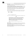
Installing the CMM321 in the PLC
For general information about module and system installation, refer to GFK-0356, Series 90-30
Programmable Controller Installation Manual.
Equipment Required to Perform the Installation Procedures
Make sure you have the items listed below before you begin.
A Series 90-30 PLC CPU baseplate, or any Series 90-30 baseplate and a Series 90-30 CPU
with power supply.
The CMM321 requires CPU version 6.50 or higher for full functionality. CPU versions
5.03 to 6.04 permit Ethernet operation with only 1 SRTP server connection.
The CMM321 requires PLC power supply IC693PWR321 (Revision K or later),
IC693PWR322, or IC693PWR330.
PLC programming software: Logic Developer (all versions), Control Version 2.01 or higher,
VersaPro version 1.0 or higher, or Logicmaster 90-30 version 6.01 or higher. (And a
compatible PC-compatible personal computer.)
If you are using the AAUI port instead of the 10Base-T port, you will need an Ethernetcompatible AAUI transceiver and Ethernet cables. (See Appendix B for more information on
the ports and transceivers.) Optional
An IC693CBL316 serial cable for the Station Manager port on the Ethernet Interface (see
Appendix B). Optional
A terminal or IBM-compatible personal computer equipped with terminal emulation
software. Optional
Notes
If your installation requires CE Mark compliance, please refer to GFK-1179,
Installation Requirements for Conformance to Standards, shipped with the PLC
programming software, for additional guidelines.
A CMM321 can be mounted on a CPU baseplate, an expansion baseplate, or a
remote baseplate. However, due to power requirements, only two Ethernet
Interface modules are permitted per baseplate using a standard power supply.
Up to four Ethernet Interface modules are permitted per baseplate using a high
capacity power supply.
2-6
TCP/IP Ethernet Communications for the Series 90™ PLC User's Manual – May 2002
GFK-1541B
2
CMM321 Installation
Use the following instructions as a guide when inserting a module into a slot in a baseplate.
These instructions assume that the power supply on the baseplate is to your left.
Warning
Do not insert or remove modules with power applied. This could cause the
PLC to Stop, damage the module, or result in personal injury.
1.
Be sure the Series 90-30 PLC baseplate power is OFF.
2.
Align the module with the desired base slot and connector. Tilt the module upwards so that
the top rear hook of the module engages the slot on baseplate.
3.
Swing the module downward until the connectors mate and the lock-lever on the bottom of
the module snaps into place engaging the baseplate notch.
4.
Visually inspect the module to be sure that it is properly seated.
5.
Connect the cable using one of the two following methods:
•
If using a 10Base-T connection, plug the cable into the 10Base-T port on the front of the
module.
•
If using the AAUI connection, connect the transceiver cable into the 14-pin AAUI port
on the bottom of the module, secure the cable, and connect the other end of the cable to
an external IEEE 802.3 compatible transceiver that is attached to the Ethernet network.
SQE must be enabled on the transceiver. (Note: The transceiver cable may be either
built-in to the transceiver or removable.)
Caution
Do not connect or disconnect a transceiver cable to the AAUI port while
power is applied to the PLC. This may blow the AAUI port fuse and/or
cause permanent damage to the Ethernet Interface.
6.
GFK-1541B
Use the PLC programming software or a Hand Held Programmer to make sure the PLC CPU
is in Stop mode.
Chapter 2 Installation
2-7
2
CMM321 Configuration
Before you can use the Ethernet Interface you must configure the module using the PLC
programming software. The PLC programming software allows you to specify the modules and
I/O that will reside in your Series 90-30 PLC rack(s). The Hand Held Programmer can not be
used to configure the Ethernet Interface.
For the Ethernet Interface specifically, the configuration software allows you to:
Define the Status address of the Ethernet Interface.
Assign the IP address for the Ethernet Interface, and optionally the subnet mask and the
gateway address.
Configure the serial ports (optional).
Configuring the Interface Using Windows-Based Programming Software
To configure theCMM321 using Control, VersaPro or Logic Developer programming software,
do the following:
1.
In Control and VersaPro, from the Browser, double-click the 90-30 Rack System–Local
Rack icon. The Local Rack Window will appear. In Logic Developer, expand the hardware
configuration and the desired rack in the browser.
2.
In Control and VersaPro, click the tab corresponding to the desired rack.
3.
Click the desired slot, press the right mouse button, and choose Add Module from the menu.
(If the slot already contains a module, choose Replace Module.) The Module Catalog dialog
box will then appear.
4.
In the Module Catalog dialog box, click the Communications tab, select IC693CMM321
Ethernet Interface, and then click the OK button. The Parameters dialog box will then appear.
5.
This dialog box will allow you to edit the module’s Ethernet parameters. To edit a parameter
value, click in the appropriate Values field. Refer to the topic “Configuration Parameters”
that follows for more information on these fields.
6.
Optionally, after you have completed the Settings tab, you can then change the default
settings of the Station Manager and Software Loader ports by clicking the appropriate tab.
We recommend leaving the serial port parameters at default settings.
7.
If you want to assign variable names to specific status points on the Ethernet card, click the
Point Reference tab. To assign a variable to a point, double-click the reference address you
want. The Insert Variable dialog box will appear, which will allow you to fill in a variable
name and description.
8.
If you want to view the power consumption of this module, click the Power Consumption tab.
After you have configured all of the module’s applicable parameters, click the OK button.
The module will now appear in the selected slot.
9.
Store the configuration to the PLC so these settings can take effect.
For more information, refer to Online Help in the PLC programming software.
2-8
TCP/IP Ethernet Communications for the Series 90™ PLC User's Manual – May 2002
GFK-1541B
2
Configuring the Interface Using the Logicmaster 90-30 Configuration Software
To configure the CMM321, access the I/O Configuration rack screen in the Logicmaster 90-30
Configuration Package, and do the following:
1.
Move the cursor to the desired rack and slot location. The slot may be either unconfigured or
previously configured.
2.
Press the Communications softkey, i.e., Comm (F6).
3.
Press Ethernet (F2).
4.
Press Enter to select the Ethernet Interface.
5.
Configure the Ethernet parameters. Refer to the topic “Configuration Parameters” that
follows for more information on these fields.
6.
Optionally, after you have assigned the Ethernet parameters, press Page Down to display the
serial port parameters. You can then change the default settings of the serial ports (optional).
Refer to the topic “Configuration Parameters” that follows for more information on these
fields. We recommend leaving the serial port parameters at default settings.
7.
After you have completed the configuration, press the Escape key to return to the rack
display. Press Escape again to save the configuration to disk.
8.
Store the configuration to the PLC so these settings can take effect.
Refer to GFK-0466, Logicmaster 90 Series 90-30/20/Micro Programming Software User’s
Manual for more information on configuring the Ethernet Interface using Logicmaster 90-30
software.
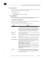
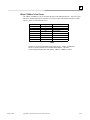
CMM321 Configuration Parameters
Ethernet Parameters
Configuration Mode: This is fixed as TCP/IP.
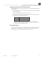
Status Address: The Status address is the location of the LAN Interface Status (LIS) bits (16
bits) and the Channel Status bits (64 bits). The Channel Status bits are always located
immediately following the LAN Interface Status bits. The Status address must be assigned to %I
memory only. The default value is the next available %I address.
Note: Do not use the 80-bits assigned to the LIS bits and Channel Status bits for
other purposes or your data will be overwritten.
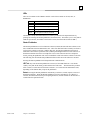
Status Length: This is fixed at 80 bits (the sum of the LIS bits and the Channel Status bits).
IP Address, Subnet Mask, Gateway IP Address, and Name Server IP Address: These values
should be assigned by the person in charge of your network (the network administrator). TCP/IP
network administrators are familiar with these parameters. It is important that these parameters
are correct, otherwise the Ethernet Interface may be unable to communicate on the network and/or
network operation may be corrupted. It is especially important that each node on the network is
assigned a unique IP address.
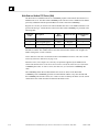
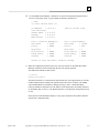
However, if you have no network administrator and are configuring a simple, isolated network
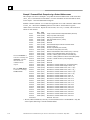
with no gateways, you can use the following range of values for the assignment of local IP
addresses:
GFK-1541B
Chapter 2 Installation
2-9
2
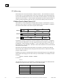
10.0.0.1
First PLC
10.0.0.2
Second PLC
10.0.0.3
Third PLC
.
.
.
.
10.0.0.255 PLC Programmer TCP or host
Also, in this case, set the subnet mask, gateway IP address, and name server IP address to 0.0.0.0.
Note
If the isolated network is ever connected to another network, the IP addresses
10.0.0.1 through 10.0.0.255 must not be used and the subnet mask, gateway IP
address, and name server IP address must be assigned by the network
administrator. The IP addresses must be assigned so that they are compatible
with the connected network. Refer to Chapter 6, “Network Administration
Support”, for more information on addressing.
See also “Determining If an IP Address Has Already Been Used”.
Converter: Allows you to account for the power consumption added by a serial port converter
(measured in Watts). Choices are 0, 0.50, and 0.60.
AAUI Transceiver (Watts): If you use an AAUI transceiver, allows you to account for the power
that the transceiver draws from the port (measured in Watts). The valid range is 0.25 to 2.00.
The default value is 0.50.
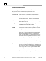
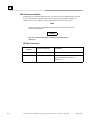
Station Manager PortParameters
Data Rate (bps): Data rate (bits per second) for the port. Choices are 300, 600, 1200, 2400,
4800, 9600‡, or 19200*.
Parity: Type of parity to be used for the port. Choices are None‡, Even, or Odd*.
Stop Bits: Enter the number of stop bits. Choices are 1*‡ or 2.
Flow Control: This parameter is currently not used by the Ethernet Interface. Changing this
parameter has no effect.
Turnaround Delay: Turnaround delay time (in milliseconds) to be used for the port. Choices
are None*‡, 10 ms, 100 ms, or 500 ms.
Timeout: This parameter is currently not used by the Ethernet Interface. Changing this
parameter has no effect.
* Default selection for the Software Loader Port.
‡ Default selection for the Station Manager Port.
2-10
TCP/IP Ethernet Communications for the Series 90™ PLC User's Manual – May 2002
GFK-1541B
2
Configuring Full-Duplex Operation
Before setting the module to Full-Duplex operation, be certain that it is connected directly to a
managed hub or switch that is manually configured for full-duplex operation on the port
connected to the IC693CMM321.
The default setting for the module is Half-Duplex. The Full Duplex parameter is an “advanced
user parameter” that can only be changed by using the CHPARM (Change Parameter) command
in the Station Manager softwar. Refer to GFK-1186, the TCP/IP Ethernet Communications
Station Manager Manual, for additional information on using Station Manager.
Warning
Contrary to the recommendation of IEEE Std. 802.3, this Ethernet Interface
module does NOT support autonegotiation of half/full-duplex. Attempting fullduplex operation of this interface with a repeater or half-duplex network
(including auto-negotiating hubs and switches) can cause severe network
performance degradation, increased collisions, late collisions, CRC errors, and
undetected data corruption.
If the module is configured in the Full-Duplex mode (see above), you can change it back to its
default value of Half-Duplex by using the Station Manager CHPARM command.
GFK-1541B
Chapter 2 Installation
2-11
2
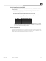
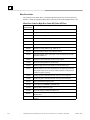
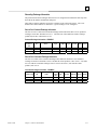
Verifying Proper Power-Up of the CMM321
Powering-up the Ethernet Interface
After configuring the CMM321, follow the procedure below to be sure it is operating correctly.
1.
Turn power OFF to the PLC for 3–5 seconds, then turn the power back ON. This will initiate
a series of diagnostic tests.
The OK LED will blink indicating the progress of power-up.
2.
The LEDs will have the following pattern upon successful power-up. At this time the
Ethernet Interface is fully operational and on-line.
LED
OK
ON
Ethernet Interface Online
LAN
ON or blinking
FDX
ON Solid if Full Duplex mode is active OFF
if Full Duplex mode is not active
STAT
ON
If STAT LED is OFF, check the PLC Fault Table. Alternatively, use the Station
Manager LOG command as explained in GFK-1186, TCP/IP Ethernet Communications
for the Series 90 PLC Station Manager Manual.
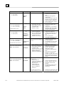
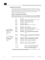
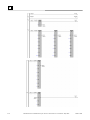
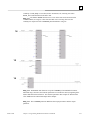
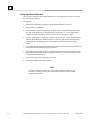
Problems During Power-up
If a problem is detected during power-up, the CMM321 may not transition directly to the
Operational State. If the Interface does not transition to Operational, check the LED pattern on
the Interface and refer to the following diagram and table for suggestions.
2-12
TCP/IP Ethernet Communications for the Series 90™ PLC User's Manual – May 2002
GFK-1541B
2
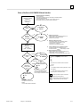
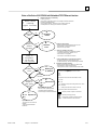
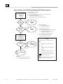
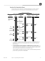
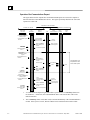
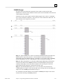
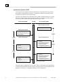
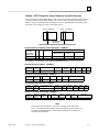
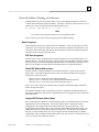
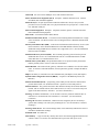
States of the Series 90-30 CMM321 Ethernet Interface
1
Ethernet Interface
Initializing 1
(approx. 2-10
seconds)
Diagnostics
Pass?
The Ethernet Interface is initialized by
- Powering-up the PLC
- Storing a new configuration to the PLC with changes for the Ethernet Interface
- Pressing the Restart pushbutton
- Issuing a Station Manager RESTART, LOAD, or MAINT command
- Internal System Error occurring when Interface is Operational
A
Hardware
Failure
No
Yes
Load
Request or
Software
Corrupted?
Ye
s
2
B
2
Software
Load
3
No
C
Waiting for
Configuration from
4
PLC CPU
(max. 2 minutes)
5
Done
Yes 3
IP address =
0.0.0.0
No
Maintenance
Request or
Fatal System
Error?
No
F
z Operational
z/ ∗/
z/
z/
Chapter 2 Installation
D
IP Address
z/ ∗/ Waiting for
IP Address
4
Received
Yes
5
E
Maintenance
z/ ∗/
z/
Maintenance
- Client and server capability disabled
- Uses default Advanced Parameters
- Permits changes to Advanced Parameters
Operational
- Full support for client and server
capability
- Uses user defined Advanced Parameters
GFK-1541B
Software Load Caused by
- Restart pushbutton pushed until bottom LED turns ON
- Station Manager LOAD command issued
- Detection of corrupt software
Waiting for IP Address Caused by
- Not configuring Interface using configuration software
- Configuring Interface with IP address = 0.0.0.0
- New CPU with no configuration
- CPU failure to communicate with Interface
Continue to Maintenance or Operational Caused by
- IP address received from network BOOTP server
- IP address entered by BOOTP Station Manager command
Maintenance Request Caused by
- Restart pushbutton pushed until bottom two LEDs turn ON
- Station Manager MAINT command issued
- Fatal System Error while in Operational State forced a restart
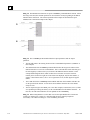
Symbols
The LEDs are labeled from top to bottom as follows:
OK
LAN
SER
STAT
The symbols used for the LEDs are defined as follows:
= OFF
z
= ON
= Slow Blink; multiple slow blinking LEDs blink in unison
= Fast Blink
∗
= Traffic (blinks when there is traffic on the line)
The process symbols are defined as follows:
= Temporary condition; requires no intervention
= Decision point during power-up
= Interface State; normally the Interface remains
in a State unless there is user intervention
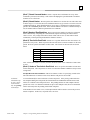
2-13
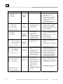
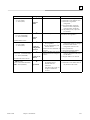
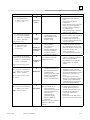
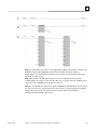
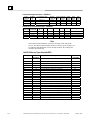
2
LED Pattern
❍
❍
❍
❍
Where Stopped
A
OK (OFF)
LAN (OFF)
FDX (OFF)
STAT (OFF)
Possible Cause
Fatal Hardware Error.
Hardware
Failure
✫
✫
✫
✫
OK (Slowblink)
LAN (Slowblink)
FDX (Slowblink)
STAT (Slowblink)
B
Restart pushbutton until
bottom LED turns ON.
Station Manager LOAD
command issued.
Software corrupt.
Did not configure slot using
PLC Programmer.
New CPU with no
configuration.
CPU not communicating
with Ethernet Interface
(Condition can last a
maximum of 2 minutes.)
Interface’s IP address has not
been configured or has been
configured as 0.0.0.0.
Software
Loader
Corrective Actions
Make sure the PLC has power.
Examine PLC Fault Table for clues.*
Recheck PLC Programmer
configuration.
Power off baseplate, inspect the
Interface for loose components,
reseat the Interface, and Restart.
Try a different slot.
If the problem persists, replace the
Interface or PLC hardware.
Connect a PC Software Loader and
load new software. See Appendix C.
Cycle power or press Restart
pushbutton again for less than 5
seconds to restart the Interface and
clear the load request.
All LEDs blink in unison.
✫
❍
❍
❍
C
OK (Slowblink)
LAN (OFF)
FDX (OFF)
STAT (OFF)
Waiting for
Configuration
from PLC
OK (Slowblink)
✫
●/∗/❍ LAN (ON/Traffic/OFF)
FDX (OFF/Slowblink)
❍
STAT (Slowblink)
✫
D
Waiting for IP
Address
Use PLC Programmer configuration
software to configure the Interface
then store the configuration to the
PLC CPU.
Make sure Interface is in the correct
slot on the baseplate.
Power cycle the PLC.
Clear faults and Restart Interface.
Use PLC Programmer to configure
the Interface with a non-zero IP
address.
Use a BOOTP server to provide
Interface with a non-zero IP address.
OK and STAT blink in unison.
✫
●/∗/❍
✫
●/❍
OK (Slowblink)
E
Maintenance
LAN (ON/Traffic/OFF)
FDX (Slowblink)
STAT (ON/OFF)
OK and SER blink in unison.
OK (ON)
●
●/∗/❍ LAN (ON/Traffic/OFF)
●/❍ FDX (ON/OFF)1
●/❍ STAT (ON/OFF)
F
Operational
1
Restart pushbutton pressed
until bottom two LEDs turn
ON.
Station Manager MAINT
command issued.
Internal System Error when
Interface was Operational
caused a restart and
entrance into Maintenance.
If the LAN LED is OFF,
the problem may be:
Network cable or
transceiver not connected to
Interface or bad transceiver.
Network cable not
terminated properly.
SQE not enabled on
transceiver.
If the STAT LED is OFF,
an exception condition has
occurred.
If you did not intend to enter
Maintenance press the Restart
pushbutton for less than 5 seconds.
This clears the Maintenance request.
Examine PLC Fault Table for clues.*
If you need to use the Station
Manager to troubleshoot a problem,
see GFK-1186, TCP/IP Ethernet
Communications for the Series 90
PLC Station Manager Manual.
Connect cable and transceiver
properly. Replace transceiver.
Terminate network cable properly.
Set SQE ON on transceiver in accord
with manufacturer’s instructions.
Examine PLC Fault Table to find out
why the STAT LED is OFF. *
FDX should be ON if Full
Duplex mode is activated;
otherwise, it should be OFF.
* Identify the PLC fault message using the PLC Programmer, then refer to Table 8-1 in Chapter 8 for corrective actions.
2-14
TCP/IP Ethernet Communications for the Series 90™ PLC User's Manual – May 2002
GFK-1541B
2
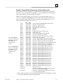
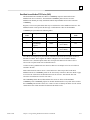
Pinging TCP/IP Ethernet Interfaces on the Network
PING (Packet InterNet Grouper) is the name of a program used on TCP/IP networks to test
reachability of destinations by sending them an ICMP echo request message and waiting for a
reply. Most nodes on TCP/IP networks, including the CMM321, implement a PING command.
You should ping each installed Ethernet Interface. When the Ethernet Interface responds to the
ping, it verifies that the interface is operational and configured properly. Specifically, it verifies
that acceptable TCP/IP configuration information has been stored to the Interface.
Pinging the Interface from a UNIX® host or a PC Running TCP/IP Software
A ping command can be executed from a UNIX host or PC running TCP/IP (since most TCP/IP
communications software provides a ping command) or from another Ethernet Interface.* When
using a PC or UNIX host, the user can refer to the documentation for the ping command, but in
general all that is required is the IP address of the remote host as a parameter to the ping command.
For example, at the command prompt type:
ping
10.0.0.1
Determining If an IP Address Has Already Been Used
It is very important not to duplicate IP addresses. To determine if you have configured your
Ethernet Interface with the same IP address as another node:
1.
Disconnect your Interface from the LAN.
2.
Ping the disconnected Interface’s IP address. If you get an answer to the ping, then the
chosen IP address is already in use by another node. You must correct this situation by
assigning unique IP addresses.
* To use another GE Fanuc Ethernet Interface, refer to the PING command in GFK-1186, TCP/IP
Ethernet Communications for the Series 90 PLC Station Manager Manual.
® UNIX is a registered trademark exclusively licensed through X/Open Company LTD.
GFK-1541B
Chapter 2 Installation
2-15
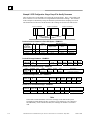
2
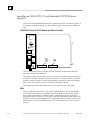
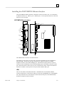
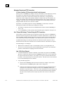
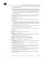
Installing an IC693CPU364 with Embedded TCP/IP Ethernet
Interface
The CPU364 with Embedded Ethernet Interface is mounted on the Series 90-30 PLC baseplate. It
is connected to an Ethernet network via a 10Base-T port or a user-provided transceiver cable and
transceiver via an AAUI port.
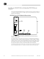
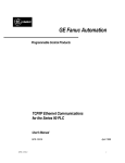
IC693CPU364 Series 90-30 CPU Module with Ethernet Interface
EOK
LAN
STAT
PS
PORT
CPU364
ON
OFF
RESTART
PUSHBUTTON
ETHERNET
RESTART
STATION
MGR
RS-232
AAUI
FUSE
DEFAULT
STATION
ADDRESS
LABEL
SERIAL
NUMBER
LABEL
10BASET
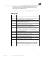
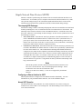
The Series 90-30 CPU364 has several user-accessible elements (only the Ethernet Interface
elements are discussed here.)
Three Ethernet LEDs are located at the top left of the board. The Ethernet Restart pushbutton is
located below the LEDs. The RS-232 serial port with the RJ-11 connector (similar to a modular
telephone connector) is used to connect to Station Manager and to load software updates. Below
the serial port are two ports, either one of which can be used to connect to the Ethernet network:
the 14-pin AAUI connector (Transceiver port) and the 10Base-T, RJ-45 network port.
The default station address (MAC address) label, serial number label, and replaceable AAUI port
fuse are concealed by the front cover. The front cover must be removed to access these items.
2-16
TCP/IP Ethernet Communications for the Series 90™ PLC User's Manual – May 2002
GFK-1541B
2
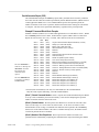
LEDs
There are four LEDs on the CPU364: EOK, LAN, STAT, and PS PORT (on some early models
of the CPU364, the PS PORT LED is labeled “SNP”). The PS (Power Supply) PORT LED is not
Ethernet related; it indicates the presence of serial traffic through the serial port of the PLC’s
power supply. Each of the three Ethernet LEDs (EOK, LAN, and STAT) can be ON, OFF,
BLINKING slow, or BLINKING fast. They indicate the state of the Ethernet Interface, traffic on
the network port (LAN LED), and that an exception event has occurred.
The three Ethernet LEDs are briefly turned ON whenever a restart is performed in the Operational
state by pressing and releasing the Restart pushbutton (described below). This allows you to
verify that the Ethernet LEDs are operational.
Ethernet Restart Pushbutton
The Ethernet Restart pushbutton serves four functions: LED test, Restart, Restart and enter
Software Load state, and Restart and enter Maintenance state. These four functions behave
similarly in all states except for the Software Load state. While in this state, pressing the
pushbutton will cause an immediate restart into the Operational state (without performing the
LED test) if the software in the Ethernet Interface has not been corrupted or erased. If the
software has been corrupted or erased, pressing the pushbutton will cause an immediate restart
back into the Software Load state. The following text describes Restart pushbutton behavior
while not in the Software Load state.
Pressing the Ethernet Restart pushbutton will disrupt Ethernet communications.
LED Test: Any time the Ethernet Restart pushbutton is released, the three Ethernet LEDs flash
ON. The operator should visually verify that the three LEDs go OFF and then ON at this time.
Then the Interface performs either a restart, a restart and enter Software Load state, or a restart
and enter Maintenance state, depending on the duration that you press the pushbutton.
Restart: Pressing the Ethernet Restart pushbutton momentarily (less than 5 seconds) requests a
restart of the Ethernet Interface. When the Restart pushbutton is pressed, the three Ethernet LEDs
go out. When it is released, the three Ethernet LEDs flash ON, then power-up diagnostics run,
and the software on the Interface is restarted into the Operational state.
GFK-1541B
Chapter 2 Installation
2-17
2
Restart and Enter Software Load State: Pressing and holding the Restart pushbutton until the
bottom LED (STAT) turns ON (between 5 and 10 seconds) forces a restart and requests entrance
to the Software Load state. A reload is used to install a software update into the module and is
not part of normal operation. When the Restart pushbutton is pressed, all LEDs go out. After
approximately 5 seconds have elapsed, the STAT LED (bottom LED) comes ON, to indicate that
the Ethernet Interface will request a reload. After the Restart pushbutton is released, the three
Ethernet LEDs flash ON, then power-up diagnostics run, and the Ethernet Interface waits for the
software load with the three Ethernet LEDs blinking in unison.
Notes
Reloading the Ethernet Interface requires the attachment of the PC Software
Loader to the RS-232, RJ-11 port and initiating a load with the PC Software
Loader. The PC Software Loader is a separate software utility that updates the
communications software in the Ethernet Interface. This utility is supplied with
any updates to the Ethernet Interface software. See Appendix C, “Upgrading
the Ethernet Interface Firmware”, for more information.
At any time before you initiate a load with the PC Software Loader when the
Ethernet Interface is in the Software Load State, you can restart the Ethernet
Interface by pressing the Restart pushbutton. Pressing this pushbutton will
immediately cause the board to restart. If the reload has been initiated, see
Appendix C, “Upgrading the Ethernet Interface Firmware”, for more
information.
Restart and Enter Maintenance State: Pressing and holding the Restart pushbutton until the
bottom two LEDs turn ON (approximately 10 seconds) forces a restart and requests entrance to
the Maintenance state. Maintenance state must be invoked to change Advanced Parameters.
While in Maintenance state, all Advanced Parameters revert to their default value. When the
Restart pushbutton is pressed, all LEDs go out. After approximately 5 seconds, the STAT LED
comes ON, then after approximately a total of 10 seconds have elapsed, the LAN LED also comes
ON, to indicate that the Ethernet Interface will request entry to the Maintenance state. After the
Restart pushbutton is released, the three Ethernet LEDs flash ON then power-up diagnostics run
and the Ethernet Interface enters the Maintenance state.
Notes
In any case, any data being transferred by the Ethernet Interface at the time of
the Restart will be lost.
The Restart pushbutton is not operable during the diagnostic phase of power-up.
The Ethernet Interface is in diagnostic phase when the EOK LED is
BLINKING fast and the other Ethernet LEDs are OFF.
2-18
TCP/IP Ethernet Communications for the Series 90™ PLC User's Manual – May 2002
GFK-1541B
2
Ports on the CPU364
RS-232, RJ-11 Port (Station Manager Port)
The Station Manager port uses a 6-pin, RJ-11 “phone jack” connector. This port is used to
connect a terminal or terminal emulator to access the Station Manager software on the Ethernet
Interface. It is also used to connect to the PC Software Loader in case the communications
software in the Ethernet Interface needs to be updated. An IC693CBL316 cable (or equivalent) is
needed to connect the terminal, emulator, or Software Loader to the Ethernet Interface (see
Appendix B, “Communications Ports Characteristics”). On earlier versions of the CPU364
module, this port was labeled “Port 1 RS-232.”
Ethernet Ports
There are two Ethernet ports on the CPU364. Only one port can be used at a time. The Ethernet
Interface automatically detects the Ethernet port in use; special configuration is not required.
AAUI (Transceiver) Port
The 14-pin AAUI port provides the electrical and mechanical interface to a user-provided IEEE
802.3 transceiver cable, which connects the AAUI Port to an external Ethernet-compatible
transceiver (see Appendix B, “Communications Ports Characteristics”, for the characteristics of
the AAUI Port and suggested transceivers). The external transceiver is directly connected to the
Ethernet cable.
Caution
Do not connect or disconnect a transceiver cable to the AAUI port while
power is applied to the PLC. This may blow the AAUI port fuse and/or
cause permanent damage to the Ethernet Interface.
10Base-T, RJ-45 Port
This 8-pin, RJ-45 port provides a direct connection to a 10Base-T (twisted pair) Ethernet network
without an external transceiver.
GFK-1541B
Chapter 2 Installation
2-19
2
CPU364 Labels
Default Station Address Label
The Default Station Address label lists the MAC address to be used by this Interface.
Serial Number Label
The Serial Number Label indicates the serial number of this Interface.
Replaceable Surface Mount Fuse
A user-replaceable fuse is provided on the DC power that is supplied by the Ethernet Interface to
the AAUI network port for use by an external transceiver. Replace only with a surface mount
2.69x2.69x6.1mm, 125V, 1A, fast-acting fuse (such as catalog number R454 001 made by
LittelFuse; http://www.littelfuse.com). You may order this fuse from GE Fanuc. The part
number is 44A725214-001.
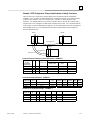
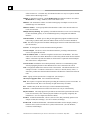
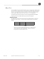
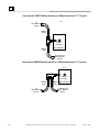
Removing and Installing the Fuse
2-20
1.
Be sure the Series 90-30 PLC baseplate power is OFF.
2.
Remove the CPU364 module from the baseplate.
3.
Remove the front shroud. The CPU364 is a two-board module, the fuse is located between
the AAUI port and the 10Base-T port. See Figure 3-1.
4.
Remove the blown fuse using a pair of small, bent-nose pliers.
5.
Insert the new fuse. Make sure the fuse is seated properly.
6.
Replace the front shroud and re-insert the CPU364 module.
7.
Restore power to the baseplate.
TCP/IP Ethernet Communications for the Series 90™ PLC User's Manual – May 2002
GFK-1541B
2
Installing the CPU364 in the PLC
For general information about module and system installation, refer to GFK-0356, Series 90-30
Programmable Controller Installation Manual.
Equipment Required to Perform the Installation Procedures
Make sure you have the items listed below before you begin.
A Series 90-30 PLC CPU baseplate with power supply. The Series 90-30 CPU364 requires
PLC power supply IC693PWR321 (Revision K or later), IC693PWR322, or IC693PWR330.
PLC programming software: Logic Developer (all versions), Control Version 2.01 or higher,
VersaPro version 1.0 or higher, or Logicmaster 90-30 version 6.01 or higher. (And a
compatible PC-compatible personal computer.)
Ethernet cables and, if using the AAUI port, an Ethernet-compatible AAUI transceiver. (See
Appendix B, “Communications Port Characteristics”, for more information.)
A serial cable for the Station Manager port on the Ethernet Interface (see Appendix B).
Optional
A terminal or IBM-compatible personal computer equipped with terminal emulation
software. Optional
Note: If your installation requires CE Mark compliance, please refer to GFK-1179,
Installation Requirements for Conformance to Standards, for additional guidelines.
CPU364 Installation
Use the following instructions as a guide when inserting a module into a slot in a baseplate.
These instructions assume that the power supply on the baseplate is to your left.
Warning
Do not insert or remove modules with power applied. This could cause the
PLC to Stop, damage the module, or result in personal injury.
1.
2.
3.
4.
5.
Be sure the Series 90-30 PLC baseplate power is OFF.
Align the module with the CPU’s base slot (slot 1) and connector. Tilt the module upwards
so that the top rear hook of the module engages the slot on baseplate.
Swing the module downward until the connectors mate and the lock-lever on the bottom of
the module snaps into place engaging the baseplate notch.
Visually inspect the module to be sure that it is properly seated.
Connect one of the Ethernet ports on the Ethernet Interface to the network. If you are using
an external transceiver, connect the transceiver cable to the 14-pin AAUI port of the Ethernet
Interface. Secure the cable. The other end of the transceiver cable should be connected to an
external IEEE 802.3 compatible transceiver which is attached to the Ethernet network. SQE
must be enabled on the transceiver. (Note: The transceiver cable may be built-in to the
transceiver or removable.)
Caution
Do not connect or disconnect a transceiver cable to the AAUI port while
power is applied to the PLC. This may blow the AAUI port fuse and/or
cause permanent damage to the Ethernet Interface.
6.
7.
GFK-1541B
Restore power to the baseplate.
Use the PLC programming software or a Hand Held Programmer to make sure the PLC CPU
is in Stop mode.
Chapter 2 Installation
2-21
2
CPU364 Configuration
Before you can use the Ethernet Interface with the Series 90-30 PLC, you must configure the
Interface using the PLC programming software. The PLC programming software allows you to
specify the modules and I/O that will reside in your Series 90-30 PLC rack(s). The Hand Held
Programmer can not be used to configure the Ethernet Interface.
For the Ethernet Interface specifically, the configuration software allows you to:
Define the Status address of the Ethernet Interface.
Assign the IP address for the Ethernet Interface, and optionally the subnet mask, the gateway
address, and the name server address.
Configure the serial ports (optional).
Configuring the Interface Using Windows-Based Programming Software.
To configure the Ethernet Interface using Logic Developer, Control or VersaPro programming
software, do the following:
1.
In Control and VersaPro, from the Browser, double-click Hardware Configuration icon.
The Local Rack Window will appear. In Logic Developer, expand the hardware
configuration and the main rack in the browser.
2.
In Control and VersaPro, click the Main tab.
3.
Click the CPU slot, press the right mouse button, and choose Replace Module. The Module
Catalog dialog box will appear.
4.
In the Module Catalog dialog box, select CPU model IC693CPU364, then click the OK
button. Follow the instructions on the screen until the Parameters dialog box appears.
5.
The Parameters dialog box will allow you to edit the module’s parameters. To edit a
parameter value, click the desired tab, then click in the appropriate Values field. The
Settings, Scan, and Memory tabs contain parameters that pertain directly to CPU operation.
Refer to Online Help for more information.
6.
The Ethernet and RS-232 tabs contain parameters directly related to the embedded Ethernet
Interface’s functionality. Some fields in the Ethernet tab must be filled in. The default
settings for the RS-232 tabs can be used. Refer to the topic “Configuration Parameters” that
follows for information on these fields. We recommend leaving the serial port parameters at
default settings.
7.
If you want to view the power consumption of this module, click the Power Consumption tab.
After you have configured all of the module’s applicable parameters, click the OK button.
The module will now appear in the selected slot.
8.
Store the configuration to the PLC so these settings can take effect.
For more information, refer to Online Help in the PLC programming software.
2-22
TCP/IP Ethernet Communications for the Series 90™ PLC User's Manual – May 2002
GFK-1541B
2
Configuring the Interface Using the Logicmaster 90-30 Configuration Software
To configure the Ethernet Interface, access the I/O Configuration rack screen in the Logicmaster
90-30 Configuration Package, and do the following:
1.
Move the cursor to the CPU slot (slot1) and press Zoom (F10) to access the CPU
configuration screen.
2.
If the current CPU is the CPU364, continue to step 3. Otherwise, press CPU (F1) to access
the CPU selection menu. Use the arrow keys to highlight the CPU364 (IC693CPU364),
press Enter to select it, and then press Y to replace the module.
3.
The initial configuration screen contains the actual CPU configuration parameters. Press
Page Down to access the configuration screens for the Ethernet Interface (Ethernet
parameters and RS-232 serial port parameters).
4.
Configure the Ethernet parameters. Refer to the topic “Configuration Parameters” that
follows for more information on these fields.
5.
Optionally, after you have assigned the Ethernet parameters, press Page Down to display the
serial port parameters. You can then change the default settings of the serial ports (optional).
Refer to the topic “Configuration Parameters” that follows for more information on these
fields. We recommend leaving the serial port parameters at default settings.
6.
After you have completed the configuration, press the Escape key to return to the rack
display. Press Escape again to save the configuration to disk.
7.
Store the configuration to the PLC so these settings can take effect.
Refer to GFK-0466, Logicmaster 90 Series 90-30/20/Micro Programming Software User’s
Manual for more information on configuring the Ethernet Interface using Logicmaster 90-30
software.
CPU364 Configuration Parameters
Ethernet Parameters
Configuration Mode: This is fixed as TCP/IP.
Adapter Name: A symbolic name representation of the associated IP address. The character set
is listed in Chapter 6, “Network Administration Support”. The Adapter Name is associated with
the IP address used in Ethernet Global Data. If supported in the PLC programming software,
view all adapter names in Hardware Configuration by going to the Edit menu, choosing Rack
Operations, and selecting Name Resolution. Adapter names are listed in the Adapter Names tab.
Status Address: The Status Reference Type is the location of the LAN Interface Status (LIS)
bits (16 bits) and the Channel Status bits (64 bits). The Channel Status bits are always located
immediately following the LAN Interface Status bits. The Status address can be assigned to %I,
%Q, %R, %AI or %AQ memory. The default value is the next available %I address.
Note
Do not use the 80-bits assigned to the LIS bits and Channel Status bits for other
purposes or your data will be overwritten.
GFK-1541B
Chapter 2 Installation
2-23
2
Status Length: This is the sum of the LIS bits and the Channel Status bits. This value is
automatically set to either 80 bits (for %I and %Q Status address locations) or 5 words (for %R,
%AI, and %AQ Status address locations).
IP Address, Subnet Mask, Gateway IP Address, and Name Server IP Address: These values
should be assigned by the person in charge of your network (the network administrator). TCP/IP
network administrators are familiar with these parameters. It is important that these parameters
are correct; otherwise, the Ethernet Interface may be unable to communicate on the network
and/or network operation may be corrupted. It is especially important that each node on the
network is assigned a unique IP address.
However, if you have no network administrator and are using a simple isolated network with no
gateways, you can use the following range of values for the assignment of local IP addresses:
10.0.0.1
10.0.0.2
10.0.0.3
.
.
.
10.0.0.255
First PLC
Second PLC
Third PLC
.
.
.
PLC Programmer TCP or host
Also, in this case, set the subnet mask, gateway IP address, and name server IP address to 0.0.0.0.
Note
If the isolated network is ever connected to another network, the IP addresses
10.0.0.1 through 10.0.0.255 must not be used and the subnet mask, gateway IP
address, and name server IP address must be assigned by the network
administrator. The IP addresses must be assigned so that they are compatible
with the connected network. Refer to Chapter 6, “Network Administration
Support”, for more information on addressing.
See also “Determining If an IP Address Has Already Been Used” in this
section.
Network Time Sync: Selection of the method used to synchronize the real-time clocks over the
network. Currently the choices are None/DISABLED (for no network time synchronization) and
SNTP/ENABLED (for synchronization to remote SNTP servers on the network).
AAUI Transceiver Power (Watts): Allows you to account for the power consumption added by
the AAUI Transceiver attached to the Ethernet module (measured in Watts). The valid range is
0.0 to 2.00. The default value is 0.0.
2-24
TCP/IP Ethernet Communications for the Series 90™ PLC User's Manual – May 2002
GFK-1541B
2
Serial Port Parameters
These parameters are for the RS-232, RJ-11 serial port on the CPU364 module. This port is used
for both the Station Manager connection and for connecting to the Software Loader. The
Software Loader settings take effect automatically when the Ethernet Interface enters the
“Software Load” state. For all other states the Station Manager settings take effect. Refer to
“Verifying Proper Power-Up of the Ethernet Interface”, for more information on states of the
Ethernet Interface.
Data Rate (bps): Data rate (bits per second) for the port. Choices are 300, 600, 1200, 2400,
4800, 9600‡, or 19200*.
Parity: Type of parity to be used for the port. Choices are None‡, Even, or Odd*.
Stop Bits: Enter the number of stop bits. Choices are 1*‡ or 2.
Flow Control: Type of flow control to be used for the port. Choices are Hardware, Software, or
None*‡. The Software selection has no effect.
Modem TT (Turnaround Delay): Turnaround delay time to be used for the port. The value
entered is the number of 10 ms increments for the Turnaround delay. Choices are 0*‡-255. (e.g.
a value of 100 will provide a 1000 ms, or 1 second, Turnaround delay)
Timeout: This parameter is currently not used by the Ethernet Interface. Changing this
parameter has no effect.
* Default selection for the Software Loader Port.
‡ Default selection for the Station Manager Port.
GFK-1541B
Chapter 2 Installation
2-25
2
Verifying Proper Power-Up of the CPU364 Ethernet Interface
After configuring the Ethernet Interface, follow the procedure below to verify that the Ethernet
Interface is operating correctly.
1.
Turn power OFF to the PLC for 3–5 seconds, then turn the power back ON. This will initiate
a series of diagnostic tests.
The EOK LED will blink indicating the progress of power-up.
2.
The Ethernet LEDs will have the following pattern upon successful power-up. At this time
the Ethernet Interface is fully operational and on-line.
LED
EOK
LAN
STAT
Ethernet Interface Online
●
(ON)
●/✲ (ON/Traffic)
●
(ON)
If the STAT LED is OFF, check the PLC Fault Table. Alternatively, use the Station
Manager LOG command as explained in GFK-1186, TCP/IP Ethernet Communications
for the Series 90 PLC Station Manager Manual.
Problems During Power-up
If a problem is detected during power-up, the Ethernet Interface may not transition directly to the
Operational State. If the Interface does not transition to Operational, check the LED pattern on
the Interface and refer to the following chart and table for corrective actions.
2-26
TCP/IP Ethernet Communications for the Series 90™ PLC User's Manual – May 2002
GFK-1541B
2
States of the Series 90-30 CPU364 with Embedded TCP/IP Ethernet Interface
1
Ethernet Interface
Initializing1
(approx. 2-6 seconds)
The Ethernet Interface is initialized by
- Powering-up the PLC
- Storing a new configuration to the PLC with changes for the Ethernet Interface
- Pressing the Restart pushbutton
- Issuing a Station Manager RESTART, LOAD, or MAINT command
- Internal System Error occurring when Interface is Operational
A
Hardware
Failure
No
Diagnostics
Pass?
Yes
Load
Request or
Software
Corrupted?
Yes
2
B
2
Software
Load
3
No
C
Waiting for
Configuration
from PLC CPU
(max. 2 seconds)
4
5
Done
IP address =
0.0.0.0
Yes
3
D
Waiting for
z/ ∗/ IP Address
No
IP Address
Received
4
Software Load Caused by
- Restart pushbutton pushed until bottom LED turns ON
- Station Manager LOAD command issued
- Detection of corrupt software
Waiting for IP Address Caused by
- Not configuring Interface using configuration software
- Configuring Interface with IP address = 0.0.0.0
- New CPU with no configuration
- CPU failure to communicate with Interface
Continue to Maintenance or Operational Caused by
- IP address received from network BOOTP server
- IP address entered by BOOTP Station Manager command
Maintenance Request Caused by
- Restart pushbutton pushed until bottom two LEDs turn ON
- Station Manager MAINT command issued
- Fatal System Error while in Operational State forced a restart
Symbols
The LEDs are labeled from top to bottom as follows:
EOK
LAN
STAT
The symbols used for the LEDs are defined as follows:
Maintenance
Request or
Fatal System
Error?
Yes 5
No
F
z
∗
z/ / Operational
z/
z/ ∗/
z/
E
= OFF
Maintenance
z
= ON
Maintenance
- Client and server capability disabled
- Uses default Advanced Parameters
- Permits changes to Advanced Parameters
= Slow Blink; multiple slow blinking LEDs blink in unison
= Fast Blink
∗
= Traffic (blinks when there is traffic on the line)
The process symbols are defined as follows:
= Temporary condition; requires no intervention
= Decision point during power-up
= Interface State; normally the Interface remains
in a State unless there is user intervention
Operational
- Full support for client and server
capability
- Uses user defined Advanced
Parameters
GFK-1541B
Chapter 2 Installation
2-27
2
LED Pattern
❍ EOK (OFF)
❍ LAN (OFF)
❍ STAT (OFF)
Where Stopped
A
Possible Cause
Fatal Hardware Error.
Hardware
Failure
✫ EOK (Slowblink)
✫ LAN (Slowblink)
✫ STAT (Slowblink)
All LEDs blink in unison.
✫ EOK (Slowblink)
❍ LAN (OFF)
❍ STAT (OFF)
B
Software
Loader
C
Waiting for
Configuration
from PLC
✫ EOK (Slowblink)
D
●/✲/❍ LAN (ON/Traffic/OFF)
✫ STAT (Slowblink)
Waiting for IP
Address
EOK and STAT blink in unison.
✫ EOK (Slowblink)
●/✲/❍ LAN (ON/Traffic/OFF)
●/❍ STAT(ON/OFF)
E
Did not configure slot using
the PLC Programmer.
CPU not communicating
with Ethernet Interface.
(Condition can last a
maximum of 2 seconds.)
Interface’s IP address has not been
configured or has been configured
as 0.0.0.0.
Maintenance
●EOK (ON)
●/✲/❍ LAN (ON/Traffic/OFF)
●/❍ STAT(ON/OFF)
F
Operational
Restart pushbutton until the
bottom LED turns ON.
Station Manager LOAD
command issued.
Software corrupt.
Restart pushbutton until the
bottom two LEDs turn ON.
Station Manager MAINT
command issued.
Internal System Error when
Interface was Operational
caused a restart and
entrance into Maintenance.
If the LAN LED is OFF, the
problem may be:
Network cable not
connected or transceiver not
connected to Interface or
bad transceiver.
Network cable not
terminated properly.
SQE not enabled on
transceiver.
If the STAT LED is OFF, an
exception condition has occurred.
2-28
Corrective Actions
Make sure the PLC has power.
Examine PLC Fault Table for
clues.
Recheck PLC Programmer
configuration.
Power off baseplate, inspect the
Interface for loose components,
reseat the module, and Restart.
If the problem persists, replace
the PLC hardware.
Connect a PC Software Loader
and load new software. See
Appendix C.
Cycle power or press Restart
pushbutton again for less than 5
seconds to restart the Interface
and clear the load request.
Use the PLC Programmer
configuration software to
configure the Interface then store
the configuration to the PLC
CPU.
Power cycle the PLC.
Clear faults and Restart Interface.
Use the PLC Programmer to
configure the Interface with a
non-zero IP address.
Use a BOOTP server to provide
Interface with a non-zero IP
address.
If you did not intend to enter
Maintenance press the Restart
pushbutton for less than 5
seconds. This clears the
Maintenance request.
Examine PLC Fault Table for
clues.
If you need to use the Station
Manager to troubleshoot a
problem, see GFK-1186, TCP/IP
Ethernet Communications for the
Series 90 PLC Station Manager
Manual.
Connect cable and transceiver
properly. Replace transceiver.
Terminate network cable
properly.
Set SQE ON on transceiver in
accord with manufacturer’s
instructions.
Examine PLC Fault Table to find
out why the STAT LED is OFF.
TCP/IP Ethernet Communications for the Series 90™ PLC User's Manual – May 2002
GFK-1541B
2
Pinging TCP/IP Ethernet Interfaces on the Network
PING (Packet InterNet Grouper) is the name of a program used on TCP/IP networks to test
reachability of destinations by sending them an ICMP echo request message and waiting for a
reply. Most nodes on TCP/IP networks, including the Series 90-30 CPU364, implement a PING
command.
You should ping each installed Ethernet Interface. When the Ethernet Interface responds to the
ping, it verifies that the interface is operational and configured properly. Specifically it verifies
that acceptable TCP/IP configuration information has been stored to the Interface.
Pinging the Interface from a UNIX® Host or a PC Running TCP/IP Software
A ping command can be executed from a UNIX host or PC running TCP/IP (since most TCP/IP
communications software provides a ping command) or from another Ethernet Interface.* When
using a PC or UNIX host, the user can refer to the documentation for the ping command, but in
general all that is required is the IP address of the remote host as a parameter to the ping command.
For example, at the command prompt type:
ping
10.0.0.1
Determining If an IP Address Has Already Been Used
It is very important not to duplicate IP addresses. To determine if you have configured your
Ethernet Interface with the same IP address as another node:
1.
Disconnect your Interface from the LAN.
2.
Ping the disconnected Interface’s IP address. If you get an answer to the ping, then the
chosen IP address is already in use by another node. You must correct this situation by
assigning unique IP addresses.
* To use another GE Fanuc Ethernet Interface, refer to the PING command in GFK-1186,
TCP/IP Ethernet Communications for the Series 90 PLC Station Manager Manual.
® UNIX is a registered trademark exclusively licensed through X/Open Company LTD.
GFK-1541B
Chapter 2 Installation
2-29
2
Installing an IC693 CPU374 with Embedded TCP/IP Ethernet
Interface
The CPU374 with Embedded Ethernet Interface is mounted on the Series 90-30 PLC baseplate. It
is connected to an Ethernet network via either or both of its auto-sensing 10Base-T/ 100Base TX
ports.
IC693CPU374 Series 90-30 CPU Module with Ethernet Interface
EOK
PS
PORT
LAN
STAT
CPU374
ON
OFF
ETHERNET
RESTART
10/100 ETHERNET
10/100 ETHERNET
STATION
MGR
LINK/ACT
PORT 1
100Mbps
LINK/ACT
PORT 2
DEFAULT
STATION
ADDRESS
LABEL
SERIAL
NUMBER
LABEL
100Mbps
FRAME
The Series 90-30 CPU374 has several user-accessible elements (only the Ethernet Interface’s
applicable elements are discussed here.)
Three Ethernet LEDs are located at the top left of the module. The Ethernet Restart pushbutton is
located below the LEDs. The RS-232 serial port with the RJ-11 connector (similar to a modular
telephone connector) is used to connect to Station Manager. Below the serial port are twoRJ-45
ports, either or both of which can be used to connect to the Ethernet network..
The default station address (MAC address) label is located on the outside of the module.
LEDs
There are eight LEDs on the CPU374. Four of these LEDs: EOK, LAN, STAT, and PS PORT
give module status information. Four LEDS are associated with the two RJ-45 ports. The PS
(Power Supply) PORT LED is not Ethernet related; it indicates the presence of serial traffic
through the serial port of the PLC’s power supply. Each of the three Ethernet LEDs (EOK, LAN,
and STAT) can be ON, OFF, BLINKING slow, or BLINKING fast. They indicate the state of the
Ethernet Interface, traffic at the Ethernet Interface (LAN LED), and that an exception event has
occurred.
2-30
TCP/IP Ethernet Communications for the Series 90™ PLC User's Manual – May 2002
GFK-1541B
2
The seven Ethernet LEDs are briefly turned ON whenever a restart is performed in the
Operational state by pressing and releasing the Restart pushbutton (described below). This allows
you to verify that the Ethernet LEDs are operational.
Each RJ-45 port has two green LED indicators on it. The upper indicator, labeled LINK/ACT,
lights when the link is physically present and blinks when traffic is detected on the port. Traffic at
the port does not necessarily mean that traffic is present at the Ethernet Interface, because the
traffic can be going between the two ports of the switch. The lower indicator, labeled 100MBPS,
lights if the network connection is 100Mbps.
See “Verifying Proper Power-Up of the Ethernet Interface” for more LED information.
Ethernet Restart Pushbutton
The Ethernet Restart pushbutton serves two functions: LED test and Restart. These functions
behave similarly in all states.
Pressing the Ethernet Restart pushbutton will disrupt Ethernet communications (including any
communications to other devices attached to the embedded switch).
LED Test: Any time the Ethernet Restart pushbutton is pressed, the seven Ethernet LEDs flash
ON. The operator should visually verify that the LEDs go OFF and then ON at this time. Then
the Interface performs a restart.
Restart: Pressing the Ethernet Restart pushbutton requests a restart of the Ethernet Interface.
When the Restart pushbutton is pressed, the seven Ethernet LEDs go out then flash ON, then
power-up diagnostics run, and the software on the Interface is restarted into the Operational state.
Ports on the CPU374
RS-232, RJ-11 Port (Station Manager Port)
The RS-232, 6-pin, RJ-11 “phone jack” port is used to connect a terminal or terminal emulator to
access the Station Manager software on the Ethernet Interface. A cable is needed to connect the
terminal, emulator, or Software Loader to the Ethernet Interface (see Appendix B,
“Communications Ports Characteristics”).
Ethernet Ports
There are two RJ-45 Ethernet ports on the Ethernet Interface. Either or both of these ports may be
attached to other Ethernet devices. Each port automatically senses the data rate (10Mbps or
100Mbps), duplex (half duplex or full duplex), and cabling arrangement (straight through or
crossover) of the attached link.
Caution
The two ports on the Ethernet Interface must not be connected, directly or
indirectly to the same device. The hub or switch connections in an Ethernet
network must form a tree, otherwise duplication of packets may result.
CPU374 Labels
Default Station Address Label
The Default Station Address label lists the MAC address to be used by this Interface.
Serial Number Label
The Serial Number Label indicates the serial number of this Interface.
GFK-1541B
Chapter 2 Installation
2-31
2
Installing the CPU374 in the PLC
For general information about module and system installation, refer to GFK-0356, Series 90-30
Programmable Controller Installation Manual.
Equipment Required to Perform the Installation Procedures
Make sure you have the items listed below before you begin.
A Series 90-30 PLC CPU baseplate with power supply. The Series 90-30 CPU374 requires
PLC power supply IC693PWR321, (Revision K or later), IC693PWR322, or IC693PWR330.
A high capacity Power Supply is recommended as the 374 uses about 60% of a standard
Power Supply’s capacity.
PLC programming software: Logic Developer Version 2.60 or higher, Control Version 2.01
or higher, or VersaPro version 2.03 or higher. (And a compatible PC-compatible personal
computer.)
Ethernet cables.
A serial cable for the Station Manager port on the Ethernet Interface (see Appendix B).
Optional
A terminal or IBM-compatible personal computer equipped with terminal emulation
software. Optional
Note
If your installation requires CE Mark compliance, please refer to GFK-1179,
Installation Requirements for Conformance to Standards, shipped with the PLC
programming software, for additional guidelines.
CPU374 Installation
Use the following instructions as a guide when inserting a module into a slot in a baseplate.
These instructions assume that the power supply on the baseplate is to your left.
Warning
Do not insert or remove modules with power applied. This could cause the
PLC to Stop, damage the module, or result in personal injury.
2-32
1.
Be sure the Series 90-30 PLC baseplate power is OFF.
2.
Align the module with the CPU’s base slot (slot 1) and connector. Tilt the module upwards
so that the top rear hook of the module engages the slot on baseplate.
3.
Swing the module downward until the connectors mate and the lock-lever on the bottom of
the module snaps into place engaging the baseplate notch.
4.
Visually inspect the module to be sure that it is properly seated.
5.
Connect one or both of the Ethernet ports on the Ethernet Interface to the network.
6.
Restore power to the baseplate.
7.
Use the PLC programming software or a Hand Held Programmer to make sure the PLC CPU
is in Stop mode.
TCP/IP Ethernet Communications for the Series 90™ PLC User's Manual – May 2002
GFK-1541B
2
CPU374 Configuration
Before you can use the Ethernet Interface with the Series 90-30 PLC, you must configure the
Interface using the PLC programming software. The PLC programming software allows you to
specify the modules and I/O that will reside in your Series 90-30 PLC rack(s). The Hand Held
Programmer can not be used to configure the Ethernet Interface.
For the Ethernet Interface specifically, the configuration software allows you to:
Define the Status address of the Ethernet Interface.
Assign the IP address for the Ethernet Interface, and optionally the subnet mask, the gateway
address, and the name server address.
Configure the serial ports (optional).
Configuring the Interface Using Windows-Based Programming Software.
To configure the Ethernet Interface using Logic Developer, Control, or VersaPro programming
software, do the following:
1.
In Control and VersaPro, from the Browser, double-click Hardware Configuration icon.
The Local Rack Window will appear. In Logic Developer, expand the hardware
configuration and the main rack in the browser.
2.
In Control and VersaPro, click the Main tab.
3.
Click the CPU slot, press the right mouse button, and choose Replace Module. The Module
Catalog dialog box will appear.
4.
In the Module Catalog dialog box, select CPU model IC693CPU374, then click the OK
button. Follow the instructions on the screen until the Parameters dialog box appears.
5.
The Parameters dialog box will allow you to edit the module’s parameters. To edit a
parameter value, click the desired tab, then click in the appropriate Values field. The
Settings, Scan, and Memory tabs contain parameters that pertain directly to CPU operation.
Refer to Online Help for more information.
6.
The Ethernet and RS-232 tabs contain parameters directly related to the embedded Ethernet
Interface’s functionality. Some fields in the Ethernet tab must be filled in. The default
settings for the RS-232 tabs can be used. Refer to the topic “Configuration Parameters” that
follows for information on these fields. We recommend leaving the serial port parameters at
default settings.
7.
If you want to view the power consumption of this module, click the Power Consumption tab.
After you have configured all of the module’s applicable parameters, click the OK button.
The module will now appear in the selected slot.
8.
Store the configuration to the PLC so these settings can take effect.
For more information, refer to Online Help in the PLC programming software.
GFK-1541B
Chapter 2 Installation
2-33
2
CPU374 Configuration Parameters
Ethernet Parameters
Configuration Mode: This is fixed as TCP/IP.
Adapter Name: This field is set to 0.1 (the rack and slot of the Ethernet Interface) and cannot be
changed.
Status Address: The Status Reference Type is the location of the LAN Interface Status (LIS)
bits (16 bits) and the Channel Status bits (64 bits). The Channel Status bits are always located
immediately following the LAN Interface Status bits. The Status address can be assigned to %I,
%Q, %R, %AI or %AQ memory. The default value is the next available %I address.
Note
Do not use the 80-bits assigned to the LIS bits and Channel Status bits for other
purposes or your data will be overwritten.
Status Length: This is the sum of the LIS bits and the Channel Status bits. This value is
automatically set to either 80 bits (for %I and %Q Status address locations) or 5 words (for %R,
%AI, and %AQ Status address locations).
IP Address, Subnet Mask, and Gateway IP Address : These values should be assigned by the
person in charge of your network (the network administrator). TCP/IP network administrators are
familiar with these parameters. It is important that these parameters are correct; otherwise, the
Ethernet Interface may be unable to communicate on the network and/or network operation may
be corrupted. It is especially important that each node on the network is assigned a unique IP
address.
However, if you have no network administrator and are using a simple isolated network with no
gateways, you can use the following range of values for the assignment of local IP addresses:
10.0.0.1
10.0.0.2
10.0.0.3
.
.
.
10.0.0.255
2-34
First PLC
Second PLC
Third PLC
.
.
.
PLC Programmer TCP or host
TCP/IP Ethernet Communications for the Series 90™ PLC User's Manual – May 2002
GFK-1541B
2
Also, in this case, set the subnet mask, and gateway IP address to 0.0.0.0.
Note
If the isolated network is ever connected to another network, the IP addresses
10.0.0.1 through 10.0.0.255 must not be used and the subnet mask,and
gateway IP address must be assigned by the network administrator. The IP
addresses must be assigned so that they are compatible with the connected
network. Refer to Chapter 6, “Network Administration Support”, for more
information on addressing.
See also “Determining If an IP Address Has Already Been Used”.
Network Time Sync: Selection of the method used to synchronize the real-time clocks over the
network. Currently the choices are None/DISABLED (for no network time synchronization) and
SNTP/ENABLED (for synchronization to remote SNTP servers on the network).
Serial Port Parameters
These parameters are for the RS-232, RJ-11 serial port on the Ethernet Interface. This port is
used for the Station Manager connection.
Data Rate (bps): Data rate (bits per second) for the port. Choices are 1200, 2400, 4800, 9600,
or 19200.
Parity: Type of parity to be used for the port. Choices are None‡, Even, or Odd*.
Flow Control: Type of flow control to be used for the port. Choices are Hardware, Software, or
None. The Software selection has no effect.
GFK-1541B
Chapter 2 Installation
2-35
2
Advanced User Parameters
Advanced User Parameters may be set for the Ethernet Interface by creating an AUP file and
putting it into the folder for the PLC application.
The AUP file is a text file, created by any convenient text editor. The file name must be
"AUP_0_1.APF". The first line of the file must consist only of the text: "AUP_0_1". Subsequent
lines in the file many contain assignments for Advanced User Parameter values using the syntax:
<parameter name>=value
There should be no space between the parameter name and the equal or between the equal and the
value. Parameter names are the same as described in GFK-1186, TCP/IP Ethernet
Communications for the Series 90 PLC, Station Manager Manual, in the description of the
PARM command.
Parameter values are converted to lowercase unless enclosed in a pair of double quotes; the
parameter value data depends on the parameter. Numeric parameters are entered in decimal or
hexadecimal format; hexadecimal values must be terminated with an 'h' or 'H' character. IP
address parameters must be entered in standard dotted decimal format. Character string values are
case-sensitive; as with Station Manager commands uppercase parameter values must be enclosed
within a pair of double quotes.
The semicolon character delimits comments; all characters in the line following a semicolon are
ignored. An entire line may be ignored by inserting a semicolon as the first character in the line. A
blank line is also ignored.
Caution
The IEEE 802.3 standard strongly discourages the manal configuration of
duplex mode for a port (as would be possible using Advanced User
Parameters.) Before manually configuring duplex mode for a port using
AUP, be sure that you know the characteristics of the link partner and are
aware of the consequences of your selection. In the words of the IEEE
standard: "Connecting incompatible DTE/MAU combinations such as full
duplex mode DTE to a half duplex MAU, or a full-duplex station (DTE or
MAU) to a repeater or other half duplex network, can lead to severe
network performance degradation, increased collisions, ate collisions, CRC
errors, and undetected data corruption."
Note
If speed and duplex mode of a port is forced using AUP, the switch will no
longer perform automatic cable detection. This means that if you have the
switch port connected to a switch or hub port you must use a crossover
cable. If you have the switch port connected to the uplink port on a switch
or hub or if you have the switch port connected to another Ethernet device
you must use a normal cable.
An example AUP file for the CPU374 to set the IP "Time to Live (TTL)" parameter to the value 5
is shown below. This text would appear in a file named "AUP_0_1.AUP" in the directory of the
folder for the PLC:
AUP_0_1
;
; Set IP TTL to 5
ittl=5
2-36
;
TCP/IP Ethernet Communications for the Series 90™ PLC User's Manual – May 2002
GFK-1541B
2
Verifying Proper Power-Up of the CPU374 Ethernet Interface
After configuring the Interface, follow the procedure below to verify that the Ethernet Interface is
operating correctly.
1.
Turn power OFF to the PLC for 3–5 seconds, then turn the power back ON. This will initiate
a series of diagnostic tests.
The EOK LED will blink indicating the progress of power-up.
2.
The Ethernet LEDs will have the following pattern upon successful power-up. At this time
the Ethernet Interface is fully operational and on-line.
LED
EOK
LAN
STAT
Ethernet Interface Online
●
(ON)
●/✲ (ON/Traffic)
●
(ON)
If STAT LED is OFF, check the PLC Fault Table. Alternatively, use the Station
Manager LOG command as explained in GFK-1186, TCP/IP Ethernet Communications
for the Series 90 PLC Station Manager Manual.
Problems During Power-up
If a problem is detected during power-up, the Ethernet Interface may not transition directly to the
Operational State. If the Interface does not transition to Operational, check the LED pattern on
the Interface and refer to the following chart and table for corrective action.
GFK-1541B
Chapter 2 Installation
2-37
2
States of the Series 90-30 CPU374 with Embedded TCP/IP Ethernet Interface
1
Ethernet Interface
1
Initializing
(approx. 2-6
seconds)
Powering up the PLC
Storing a new configuration to the PLC with changes for the Ethernet Interface
Pressing the Restart pushbutton
Issuing a Station Manager RESTART command
Internal System Error occurring when Interface is operational
No
Diagnostics
Pass?
The Ethernet Interface is initialized by
A
Hardware
Failure
2
Yes
Load
Request or
Software
Corrupted?
Yes
2
B
Software
Load
3
No
C
4
Waiting for
Configuration from
PLC CPU
(max. 2 seconds)
Detection of corrupt software
Not configuring Interface using configuration software
Configuring Interface with IP Address = 0.0.0.0
New CPU with no configuration
CPU failure to communication with Interface
Continue to Operational State caused by
IP Address received over network
Symbols
Yes
No
Pressing the Restart pushbutton
Waiting for IP Address caused by
Done
IP address
= 0.0.0.0
Software Load caused by
3
D
z/ ∗/ Waiting for
IP Address
4
Received
E
z
z/ ∗/ Operational
z/
IP Address
The LEDs are labeled from top to bottom as follows:
EOK
LAN
STAT
The symbols use for the LEDS i the chart are:
OFF
z
ON
Slow Blink; multiple slow blinking LEDS blink in
unison
Fast Blink
∗
Traffic (blinks when there is traffic on the line.
The process symbols use in this chart are:
Temporary condition; requires no intervention
Decision point during powerup
Operational
2-38
Full support for client and server capanility
Interface State; normally the Interface remains in a
state unless there is user intervention.
Uses user-defined Advanced Parameters
TCP/IP Ethernet Communications for the Series 90™ PLC User's Manual – May 2002
GFK-1541B
2
LED Pattern
❍ EOK (OFF)
❍ LAN (OFF)
❍ STAT (OFF)
✫ EOK (Slowblink)
✫ LAN (Slowblink)
✫ STAT (Slowblink)
All LEDs blink in unison.
✫ EOK (Slowblink)
❍ LAN (OFF)
❍ STAT (OFF)
Where Stopped
A
Hardware
Failure
B
configuration.
Power off baseplate, inspect the
Software corrupt.
C
Interface for loose components,
reseat the module, and Restart.
If the problem persists, replace the
PLC hardware.
Connect a PC Software Loader and load
new software. See Appendix C.
Waiting for
Configuration
from PLC
E
Did not configure slot using the Use the PLC Programmer
configuration software to configure
the Interface then store the
configuration to the PLC CPU.
Ethernet Interface.
(Condition can last a maximum of Power cycle the PLC.
2 seconds.)
Clear faults and Restart Interface.
Interface’s IP address has not been Use the PLC Programmer to
configure the Interface with a nonconfigured or has been configured
zero IP address.
as 0.0.0.0.
PLC Programmer.
CPU not communicating with
Assign IP address over network
Operational
GFK-1541B
Corrective Actions
Make sure the PLC has power.
Examine PLC Fault Table for clues.
Recheck PLC Programmer
Software
Loader
✫ EOK (Slowblink)
D
●/✲/❍ LAN (ON/Traffic/OFF)
✫ STAT (Slowblink)
Waiting for IP
Address
EOK and STAT blink in unison.
●EOK (ON)
●/✲/❍ LAN (ON/Traffic/OFF)
●/❍ STAT(ON/OFF)
Possible Cause
Fatal Hardware Error.
Chapter 2 Installation
If the LAN LED is OFF,
the problem may be
network cable not
connected
Connect cable.
Examine PLC Fault Table to find out
why the STAT LED is OFF.
If the STAT LED is OFF, an
exception condition has
occurred.
2-39
2
Pinging TCP/IP Ethernet Interfaces on the Network
PING (Packet InterNet Grouper) is the name of a program used on TCP/IP networks to test
reachability of destinations by sending them an ICMP echo request message and waiting for a
reply. Most nodes on TCP/IP networks, including the Series 90-30 CPU374, implement a PING
command.
You should ping each installed Ethernet Interface. When the Ethernet Interface responds to the
ping, it verifies that the interface is operational and configured properly. Specifically it verifies
that acceptable TCP/IP configuration information has been stored to the Interface.
Pinging the Interface from a UNIX® Host or a PC Running TCP/IP Software
A ping command can be executed from a UNIX host or PC running TCP/IP (since most TCP/IP
communications software provides a ping command) or from another Ethernet Interface.* When
using a PC or UNIX host, the user can refer to the documentation for the ping command, but in
general all that is required is the IP address of the remote host as a parameter to the ping command.
For example, at the command prompt type:
ping
10.0.0.1
Determining If an IP Address Has Already Been Used
It is very important not to duplicate IP addresses. To determine if you have configured your
Ethernet Interface with the same IP address as another node:
1.
Disconnect your Interface from the LAN.
3.
Ping the disconnected Interface’s IP address. If you get an answer to the ping, then the
chosen IP address is already in use by another node. You must correct this situation by
assigning unique IP addresses.
* To use another GE Fanuc Ethernet Interface, refer to the PING command in GFK-1186,
TCP/IP Ethernet Communications for the Series 90 PLC Station Manager Manual.
® UNIX is a registered trademark exclusively licensed through X/Open Company LTD.
2-40
TCP/IP Ethernet Communications for the Series 90™ PLC User's Manual – May 2002
GFK-1541B
2
Installing the IC697CMM742 Ethernet Interface
The IC697CMM742 Ethernet Interface is mounted in a Series 90-70 PLC rack. It is connected to
an Ethernet network via a 10Base-T port, a 10Base2 port, or a user-provided transceiver cable and
transceiver via an AUI port.
IC697CMM742 Ethernet Interface
a45598
DISABLE ONBOARD
10Base2 PORT JUMPER
REPLACEABLE FUSE
ETHERNET
INTERFACE
MODULE OK
LEDS
LAN ONLINE
JP7
FU3
SERIAL ACTIVE
STATUS
RESTART
PUSHBUTTON
STATION MGR (RS-232)
SERIAL PORT
SERVICE OPTION
CONNECTOR
RESTART
STATION
MGR
RS
S
232
E
R
I
SERVICE
A
OPTION
L
SOFTWARE LOAD (RS-485)
SERIAL PORT
10BaseT NETWORK
PORT
S/W
LOAD
RS
485
AUI
OR
10Base2 NETWORK
PORT
LABEL
C
O
N
N
E
C
T
I
O
N
S
10
BASE
T
OR
AUI NETWORK PORT
SERIAL
NUMBER
E
T
H
E
R
N
E
T
C
O
N
N
E
C
T
I
O
N
10
BASE
2
DEFAULT STATION ADDRESS
LABEL
The CMM742 has several user-accessible elements.
Four LEDs are located at the top of the board. The Restart pushbutton is located immediately
below the LEDs. The RS-232 serial port with the RJ-11 connector (similar to a modular
telephone connector) is the Station Manager port. The RS-485 serial port with the 15-pin “D”
connector located immediately below the Station Manager port is the module’s Software Loader
port. Below these there are three ports, any one of which can be used to connect to the Ethernet
network: the 10Base-T, RJ-45 port, the AUI port, and the 10Base2, BNC port.
LEDs
There are four LEDs on the Ethernet Interface: MODULE OK, LAN ONLINE, SERIAL
ACTIVE, and STATUS. Each of these LEDs can be ON, OFF, BLINKING slow, or BLINKING
fast. They indicate the state of the Interface, traffic on the network port (LAN ONLINE LED),
and that an exception event has occurred.
GFK-1541B
Chapter 2 Installation
2-41
2
All LEDs are briefly turned ON whenever a restart is performed in the Operational state by
pressing and releasing the Restart pushbutton (described below). This allows you to verify that all
LEDs are operational.
See “Verifying Proper Power-Up of the Ethernet Interface” for more LED information.
Ethernet Restart Pushbutton
The Restart pushbutton serves four functions: LED test, Restart, Restart and enter Software Load
state, and Restart and enter Maintenance state. These four functions behave similarly in all states
except for the Software Load state. While in this state, pressing the pushbutton will cause an
immediate restart into the Operational state (without performing the LED test) if the software in
the Ethernet Interface has not been corrupted or erased. If the software has been corrupted or
erased, pressing the pushbutton will cause an immediate restart back into the Software Load state.
The following text describes Restart pushbutton behavior while not in the Software Load state.
Pressing the Restart pushbutton will disrupt Ethernet communications.
LED Test: Any time the Restart pushbutton is released all the LEDs flash ON. You should
visually verify that all the LEDs go OFF and then ON at this time. Then the Interface performs
either a restart, a restart and enter Software Load state, or a restart and enter Maintenance state,
depending on the duration that you press the pushbutton.
Restart: Pressing the Restart pushbutton momentarily (less than 5 seconds) requests a restart of
the Ethernet Interface. When the Restart pushbutton is pressed, all LEDs go out. When it is
released, all LEDs flash ON, then power-up diagnostics run, and the software on the Interface is
restarted into the Operational state.
Restart and Enter Software Load State: Pressing and holding the Restart pushbutton until the
bottom LED (STATUS) turns ON (between 5 and 10 seconds) forces a restart and requests
entrance to the Software Load state. A reload is used to install a software update into the module
and is not part of normal operation. When the Restart pushbutton is pressed, all LEDs go out.
After approximately 5 seconds have elapsed, the STATUS LED (bottom LED) comes ON, to
indicate that the Ethernet Interface will request a reload. After the Restart pushbutton is released,
all LEDs flash ON, then power-up diagnostics run, and the Ethernet Interface waits for the
software load with all LEDs blinking in unison.
Note
Reloading the Ethernet Interface requires the attachment of the PC Software
Loader to the Software Loader port and initiating a load with the PC Software
Loader. The PC Software Loader is a separate software utility that updates the
communications software in the Ethernet Interface. This utility is supplied with
any updates to the Ethernet Interface software. See Appendix C, “Upgrading
the Ethernet Interface Firmware”, for more information.
Note
At any time before you initiate a load with the PC Software Loader when the
Ethernet Interface is in the Software Load state, you can restart the Ethernet
Interface by pressing the Restart pushbutton. Pressing this pushbutton will
immediately cause the board to restart. If the reload has been initiated, see
Appendix C, “Upgrading the Ethernet Interface Firmware”, for more
information.
2-42
TCP/IP Ethernet Communications for the Series 90™ PLC User's Manual – May 2002
GFK-1541B
2
Restart and Enter Maintenance State: Pressing and holding the Restart pushbutton until the
bottom two LEDs turn ON (approximately 10 seconds) forces a restart and requests entrance to
the Maintenance state. Maintenance state must be invoked to change Advanced Parameters.
While in Maintenance state, all Advanced Parameters revert to their default value. When the
Restart pushbutton is pressed, all LEDs go out. After approximately 5 seconds, the STATUS
LED comes ON, then after approximately a total of 10 seconds have elapsed, the SERIAL
ACTIVE LED also comes ON, to indicate that the Ethernet Interface will request entry to the
Maintenance state. After the Restart pushbutton is released, all LEDs flash ON then power-up
diagnostics run and the Ethernet Interface enters the Maintenance state.
Notes
In any case, any data being transferred by the Ethernet Interface at the time of
the Restart will be lost.
The Restart pushbutton is not operable during the diagnostic phase of power-up.
The Ethernet Interface is in diagnostic phase when the MODULE OK LED is
BLINKING fast and other LEDs are OFF.
Service Option Connector
If a problem occurs with the Ethernet Interface that requires continuous removal of power from
the rack or its removal from the rack, the on-board log event data will automatically be preserved
for 2–3 days. The service option connector allows you to attach a standard battery
(IC697ACC701) to save the log event data for longer periods.
Ports on the CMM742
There are two serial ports on the Ethernet Interface: the Station Manager port (RS-232) and the
Software Loader port (RS-485).
RS-232, RJ-11 Port (Station Manager Port)
The RS-232, 6-pin, RJ-11 “phone jack”, port is used to connect a terminal or terminal emulator to
access the Station Manager software on the Ethernet Interface. A cable is needed to connect the
terminal or emulator to the Ethernet Interface (see Appendix B, “Communications Ports
Characteristics”).
RS-485, D-Type Port (Software Loader Port)
The RS-485, 15-pin, D-type port is used to connect to the PC Software Loader in case the
communications software in the Ethernet Interface needs to be updated. The characteristics of
this port are given in Appendix B, “Communications Ports Characteristics”.
GFK-1541B
Chapter 2 Installation
2-43
2
Ethernet Ports
There are three Ethernet ports on the Ethernet Interface. Only one Ethernet port may be used at a
time. The Ethernet Interface automatically detects the Ethernet port in use; special configuration
is not required. (See also the topic “Disable Onboard 10Base2 Port Jumper” below.)
Caution
Do not connect or disconnect a transceiver or network cable to the AUI or
BNC ports while power is applied to the PLC. This may blow the port fuse
and/or cause permanent damage to the Ethernet Interface.
10BaseT Port
This 8-pin, RJ-45 port provides a direct connection to a 10Base-T (twisted pair) Ethernet network
without an external transceiver.
AUI Port
This 15-pin, D-type AUI port with slide-lock provides the electrical and mechanical interface to
the user-provided IEEE 802.3 transceiver cable, which connects the AUI Port to an external
Ethernet compatible transceiver (see Appendix B, “Communications Ports Characteristics”, for
the characteristics of the AUI port). The external transceiver is directly connected to the Ethernet
cable.
10Base2, BNC Port
This BNC port provides a direct connection to a 10Base2 (thin wire) Ethernet network without an
external transceiver.
CMM742 Labels
Default Station Address Label
The Default Station Address label lists the MAC address to be used by this Interface.
Disable Onboard 10Base2 Port Jumper
This jumper (“JP7”) must be in place to ensure proper network operation only when using an
external AUI transceiver connected to the AUI port that is externally powered. This jumper is
normally not installed.
Replaceable +12VDC Fuse
A user-replaceable fuse (FU3) is provided on the +12VDC power that is supplied by the Ethernet
Interface to the AUI network port for use by an external transceiver. Replace only with a 5 x
20mm, 250V, 1 A, fast-acting fuse.
2-44
TCP/IP Ethernet Communications for the Series 90™ PLC User's Manual – May 2002
GFK-1541B
2
Installing the CMM742 in the PLC
For general information about module and system installation, refer to GFK-0262, Series 90-70
Programmable Controller Installation Manual.
Equipment Required to Perform the Installation Procedures
Make sure you have the items listed below before you begin.
Series 90-70 PLC rack.
Series 90-70 power supply.
To use the AUI port, the power supply must be one of the following types, which
provide +12 Vdc for an external transceiver on the AUI port: IC697PWR711,
IC697PWR724, or IC697PWR748.
If the AUI port will not be used, +5 Vdc is all that is required. Under these conditions,
power supply IC697PWR710 is sufficient.
A Series 90-70 CPU.
PLC programming software: Logicmaster 90-70 version 6.02 or higher or Control version
1.0 or higher (runs on a personal computer).
Ethernet cables and, if using the AUI port, an Ethernet-compatible AUI transceiver. (See
Appendix B, “Communications Ports Characteristics”, for more information.)
A serial cable for the Station Manager port on the Ethernet Interface (see Appendix B).
Optional
A terminal or IBM-compatible personal computer equipped with terminal emulation
software. Optional
A Phillips-head screwdriver.
Note
If your installation requires CE Mark compliance, please refer to GFK-1179,
Installation Requirements for Conformance to Standards, shipped with the PLC
programming software, for additional guidelines.
GFK-1541B
Chapter 2 Installation
2-45
2
CMM742 Installation
This section describes the physical mounting of the Ethernet Interface into the Series 90-70 PLC
rack. For information on the installation procedures for the rack, Series 90-70 CPU, Power
Supply, and other Series 90-70 modules, refer to GFK-0262, Series 90-70 Programmable
Controller Installation Manual.
Warning
Do not insert or remove modules with power applied. This could cause the
PLC to Stop, damage the module, or result in personal injury.
1.
Be sure the Series 90-70 PLC rack power is OFF.
2.
Slide the Ethernet Interface into the desired slot—normally the first available slot to the right
of the CPU.
Press firmly to seat the Interface, but do not force the Interface. Tighten the screws on the
top and bottom tabs.
Note
The Series 90-70 Ethernet Interface (Type 2) must be installed in the main rack;
installation in an expansion rack is not supported. The Ethernet Interface will
not operate properly if there are empty slots to the left of the slot you select.
3.
Connect one of the Ethernet ports on the Ethernet Interface to the network. If you are using
an external transceiver, connect the transceiver cable to the AUI port on the Ethernet
Interface. The other end of the transceiver cable should be connected to an external IEEE
802.3 compatible transceiver that is attached to the Ethernet network. SQE must be enabled
on the transceiver.
Caution
Do not connect or disconnect a transceiver or network cable to the AUI or
BNC ports while power is applied to the PLC. This may blow the port fuse
and/or cause permanent damage to the Ethernet Interface.
4.
2-46
Set the CPU Run/Stop switch to STOP.
TCP/IP Ethernet Communications for the Series 90™ PLC User's Manual – May 2002
GFK-1541B
2
CMM742 Configuration
Before you can use the Ethernet Interface with the Series 90-70 PLC, you must configure the
Interface using the PLC programming software. The PLC configuration software allows you to
specify the modules and I/O that will reside in your Series 90-70 PLC rack(s).
For the Ethernet Interface specifically, the configuration software allows you to:
Define the Status address of the Ethernet Interface.
Assign the IP address for the Ethernet Interface, and optionally the subnet mask, the gateway
address, and the name server address.
Configure the serial ports (optional).
Configuring the Interface Using Windows-Based Programming Software
To configure the Ethernet Interface using Logic Developer, Control, or VersaPro programming
software, do the following:
1.
In Control and VersaPro, from the Browser, double-click the 90-70 Rack System–Local
Rack icon. The Local Rack Window will appear. In Logic Developer, expand the hardware
configuration and the desired rack in the browser.
2.
In Control and VersaPro, click the tab corresponding to the desired rack.
3.
Click the desired slot, press the right mouse button, and choose Add Module from the menu.
(If the slot already contains a module, choose Replace Module.) The Module Catalog dialog
box will appear.
4.
In the Module Catalog dialog box, click the Communications tab, select IC697CMM742
Ethernet Controller Type 2, and then click the OK button. The Parameters dialog box then
will appear.
5.
This dialog box will allow you to edit the module’s Ethernet parameters. To edit a parameter
value, click in the appropriate Values field.
6.
Optionally, after you have completed the Settings tab, you can configure parameters for the
Station Manager and Software Load ports by clicking the appropriate tab. The default
settings for the serial ports can then be changed (optional). Refer to the topic “Configuration
Parameters” that follows for information on these fields. We recommend leaving the serial
port parameters at default settings.
7.
If you want to view the power consumption of this module, click the Power Consumption tab.
After you have configured all of the module’s applicable parameters, click the OK button.
The module will now appear in the selected slot.
8.
Store the configuration to the PLC so these settings can take effect.
For more information, refer to Online Help in the PLC programming software.
GFK-1541B
Chapter 2 Installation
2-47
2
Configuring the Interface Using Logicmaster 90-70 Configuration Software
To configure the Ethernet Interface, access the I/O Configuration rack screen in the Logicmaster
90-70 Configuration Package, and do the following:
1.
Move the cursor to the desired rack and slot location. The slot may be either unconfigured or
previously configured.
2.
Press the Communications softkey, i.e., Comm (F6)
3.
Press ethnet (F2).
4.
Press “↓” (down arrow) to highlight “IC697CMM742”, then press Enter to select the
Ethernet Interface.
5.
Configure the Ethernet parameters. Refer to the topic “Configuration Parameters” that
follows for more information on these fields.
6.
Optionally, after you have assigned the Ethernet parameters, press Page Down to display the
serial port parameters. You can then change the default settings of the serial ports (optional).
Refer to the topic “Configuration Parameters” that follows for more information on these
fields. We recommend leaving the serial port parameters at default settings.
7.
After you have completed the configuration, press the Escape key to return to the rack
display. Press Escape again to save the configuration to disk.
8.
Store the configuration to the PLC so these settings can take effect.
Refer to GFK-0263, Logicmaster 90-70 Programming Software User’s Manual for more
information on using Logicmaster 90-70 software.
2-48
TCP/IP Ethernet Communications for the Series 90™ PLC User's Manual – May 2002
GFK-1541B
2
CMM742 Configuration Parameters
Ethernet Parameters
Configuration Mode: This is fixed as TCP/IP.
Adapter Name: A symbolic name representation of the associated IP Address. The character set
is listed in Chapter 6, “Network Administration Support”. The Adapter Name is associated with
the IP address used in Ethernet Global Data. If supported in the PLC programming software,
view all adapter names in Hardware Configuration by going to the Edit menu, choosing Rack
Operations, and selecting Name Resolution. Adapter names are listed in the Adapter Names tab.
IP Address, Subnet Mask, Gateway IP Address, and Name Server IP Address: These values
should be assigned by the person in charge of your network (the network administrator). TCP/IP
network administrators are familiar with these parameters. It is important that these parameters
are correct, otherwise the Ethernet Interface may be unable to communicate on the network and/or
network operation may be corrupted. It is especially important that each node on the network is
assigned a unique IP address.
However, if you have no network administrator and are using a simple isolated network with no
gateways, you can use the following range of values for the assignment of local IP addresses:
10.0.0.1
First PLC
10.0.0.2
Second PLC
10.0.0.3
Third PLC
.
.
.
10.0.0.255 PLC Programmer TCP or host
Also, in this case, set the subnet mask, gateway IP address, and name server IP address to 0.0.0.0.
Note
If the isolated network is ever connected to another network, the IP addresses
10.0.0.1 through 10.0.0.255 must not be used and the subnet mask, gateway
IP address, and name server address must be assigned by the network
administrator. The IP addresses must be assigned so that they are compatible
with the connected network. Refer to Chapter 6, “Network Administration
Support”, for more information on addressing.
See also “Determining If an IP Address Has Already Been Used”.
Status Address: The Status Reference Type is the location of the LAN Interface Status (LIS)
bits (16 bits) and the Channel Status bits (64 bits). The Channel Status bits are always located
immediately following the LAN Interface Status bits. The Status address can be assigned to %I,
%Q, %R, %AI, or %AQ memory. The default value is the next available %I address.
Note
Do not use the 80 bits assigned to the LIS bits and Channel Status bits for other
purposes or your data will be overwritten.
GFK-1541B
Chapter 2 Installation
2-49
2
Status Length: This is the sum of the LIS bits and the Channel Status bits. This value is
automatically set to either 80 bits (for %I and %Q Status address locations) or 5 words (for %R,
%AI, and %AQ Status address locations).
Network Routing Pair #1, #2, #3: These parameters are used to define an IP routing partnership
with another network adapter within the same PLC system. Network routing pairs is an advanced
feature that should be set only by individuals who have detailed knowledge of PLC
communications.
Network Time Sync: Selection of the method used to synchronize the real-time clocks over the
network. Currently the choices are None (for no network time synchronization) and SNTP (for
synchronization to remote SNTP servers on the network).
Serial Port Parameters
Data Rate (bps): Data rate (bits per second) for the port. Choices are 300, 600, 1200, 2400,
4800, 9600‡, or 19200*.
Parity: Type of parity to be used for the port. Choices are None‡, Even, or Odd*.
Stop Bits: Enter the number of stop bits. Choices are 1*‡ or 2.
Flow Control: This parameter is currently not used by the Ethernet Interface. Changing this
parameter has no effect.
Turnaround Delay: Turnaround delay time (in milliseconds) to be used for the port. Choices
are None*‡, 10 ms, 100 ms, or 500 ms.
Timeout: This parameter is currently not used by the Ethernet Interface. Changing this
parameter has no effect.
* Default selection for the Software Loader Port.
‡ Default selection for the Station Manager Port.
2-50
TCP/IP Ethernet Communications for the Series 90™ PLC User's Manual – May 2002
GFK-1541B
2
Verifying Proper Power-Up of the CMM742
After configuring the Interface, follow the procedure below to verify that the Ethernet Interface is
operating correctly.
1.
Turn power OFF to the PLC for 3–5 seconds, then turn the power back ON. This will
initiate a series of diagnostic tests.
The MODULE OK LED will blink indicating the progress of power-up.
2.
The LEDs will have the following pattern upon successful power-up. At this time the
Ethernet Interface is fully operational and on-line.
LED
MODULE OK
LAN ONLINE
SERIAL ACTIVE
STATUS
Ethernet Interface Online
●
(ON)
●/✲ (ON/Traffic)
❍
(OFF)
●
(ON)
If the STATUS LED is OFF, check the PLC Fault Table. Alternatively, use the Station
Manager LOG command as explained in GFK-1186, TCP/IP Ethernet Communications
for the Series 90 PLC Station Manager Manual.
Problems During Power-up
If a problem is detected during power-up, the Ethernet Interface may not transition directly to the
Operational state. If the Interface does not transition to Operational, check the LED pattern on the
Interface and refer to the following chart and table for corrective action.
GFK-1541B
Chapter 2 Installation
2-51
2
States of the Series 90-70 CMM742 TCP/IP Ethernet Interface
1 The Ethernet Interface is initialized by
- Powering-up the PLC
- Storing a new configuration to the PLC with changes for the Ethernet Interface
- Pressing the Restart pushbutton
- Issuing a Station ManagerRESTART, LOAD, or MAINT command
- Internal System Error occurring when Interface is Operational
Ethernet Interface
Initializing 1
(approx.10-20 seconds)
No
Diagnostics
Pass?
A
Hardware
Failure
Yes
Load
Request or
Software
Corrupted?
Yes 2
B
No
Software Load Caused by
- Restart pushbutton pushed until bottom LED turns ON
- Station ManagerLOAD command issued
- Detection of corrupt software
3
Waiting for IP Address Caused by
- Not configuring Interface using configuration software
- Configuring Interface with IP address = 0.0.0.0
- New CPU with no configuration
- CPU failure to communicate with Interface
4
Continue to Maintenance or Operational Caused by
- IP address received from network BOOTP server
- IP address entered by BOOTP Station Manager command
C
Waiting for
Configuration from
PLC CPU
(max. 2 minutes)
5 Maintenance Request Caused by
Done
Yes 3
IP address =
D
z/ ∗/ Waiting for
0.0.0.0
IP Address
No
IP Address Received
Maintenance
Request or
Fatal System
Error?
No
z
z/ ∗/
z/
Yes 5
z/ ∗/
4
E
Maintenance
z/
Maintenance
- Client and server capability disabled
- Uses default Advanced Parameters
- Permits changes to Advanced Parameters
F
Operational
Operational
- Full support for client and server capability
- Uses user defined Advanced Parameters
2-52
2
Software
Load
- Restart pushbutton pushed until bottom two LEDs turn ON
- Station ManagerMAINT command issued
- Fatal System Error while in Operational State forced a restart
Symbols
The LEDs are labeled from top to bottom as follows:
MODULE OK
LAN ONLINE
SERIAL ACTIVE
STATUS
The symbols used for the LEDs are defined as follows:
= OFF
z
= ON
= Slow Blink; multiple slow blining LEDs blink in unison
= Fast Blink
∗
= Traffic (blinks when there is traffic on the line)
The process symbols are defined as follows:
= Temporary condition; requires no intervention
= Decision point during power-up
= Interface State; normally the Interface remains
in a State unless there is user intervention
TCP/IP Ethernet Communications for the Series 90™ PLC User's Manual – May 2002
GFK-1541B
2
LED Pattern
❍
❍
❍
❍
MODULE OK OFF)
LAN ONLINE (OFF)
SERIAL ACTIVE (OFF)
STATUS (OFF)
Where Stopped
A
Possible Cause
Fatal Hardware Error.
Hardware
Failure
✫
✫
✫
✫
MODULE OK (Slowblink)
LAN ONLINE (Slowblink)
SERIAL ACT. (Slowblink)
STATUS (Slowblink)
B
Software
Loader
Restart pushbutton until the
bottom LED turns ON.
Station Manager LOAD
command issued.
Software corrupt.
All LEDs blink in unison.
✫
❍
❍
❍
MODULE OK (Slowblink)
LAN ONLINE (OFF)
SERIAL ACT. (OFF)
Status (OFF)
✫ MODULE OK (Slowblink)
●/✲/❍ LAN ONL. (ON/Traffic/OFF)
❍ SER. ACT (OFF/Slowblink)
✫ STAT US (Slowblink)
C
Did not configure slot using
PLC Programmer.
New CPU with no
Waiting for
configuration.
Configuration
CPU not communicating
from PLC
with Ethernet Interface
(Condition can last a
maximum of 2 minutes.)
Interface’s
IP address has not
D
been configured or has been
configured as 0.0.0.0.
Waiting for IP
Address
MODULE OK and STATUS blink in
unison.
E
✫ MODULE OK (Slowblink)
●/✲/❍ LAN ONL. (ON/Traffic/OFF)
✫ SERIAL ACT. (Slowblink)
●/❍ STATUS (ON/OFF)
Maintenance
GFK-1541B
MODULE OK and SERIAL ACTIVE
blink in unison.
● MODULE OK (ON)
●/✲/❍ LAN ONL. (ON/Traffic/OFF)
❍ SERIAL ACTIVE (OFF)
●/❍ STATUS (ON/OFF)
F
Operational
Chapter 2 Installation
Restart pushbutton until
bottom two LEDs turn ON.
Station Manager MAINT
command issued.
Internal System Error when
Interface was Operational
caused a restart and
entrance into Maintenance.
If the LAN ONLINE LED is
OFF, the problem may be:
Network cable not
connected or transceiver not
connected to Interface or
bad transceiver.
Network cable not
terminated properly.
SQE not enabled on
transceiver.
If the STATUS LED is OFF, an
exception condition has
occurred.
Corrective Actions
Make sure the PLC has power.
Examine PLC Fault Table for
clues.*
Recheck PLC Programmer
configuration.
Power off the PLC rack, inspect the
Interface for loose components,
reseat the Interface, and Restart.
Try a different slot.
If the problem persists, replace the
Interface or PLC hardware.
Connect a PC Software Loader and
load new software. See Appendix C.
Cycle power or press Restart
pushbutton again for less than 5
seconds to restart the Interface and
clear the load request.
Use configuration software to
configure the Interface then store
the configuration to the PLC CPU.
Make sure Interface is in the correct
slot on the in the PLC rack.
Power cycle the PLC.
Clear faults and Restart Interface.
Use PLC Programmer configuration
software to configure the Interface
with a non-zero IP address.
Use a BOOTP server to provide
Interface with a non-zero IP
Address.
If you did not intend to enter
Maintenance, press the Restart
pushbutton for less than 5 seconds.
This clears the Maintenance request.
Examine PLC Fault Table for
clues.*
If you need to use the Station
Manager to troubleshoot a problem,
see GFK-1186, TCP/IP Ethernet
Communications for the Series 90
PLC Station Manager Manual.
Connect cable and transceiver
properly. Replace transceiver.
Terminate network cable properly.
Set SQE ON on transceiver in
accord with manufacturer’s
instructions.
Examine PLC Fault Table to find
out why the STATUS LED is OFF.
*
2-53
2
Pinging TCP/IP Ethernet Interfaces on the Network
PING (Packet InterNet Grouper) is the name of a program used on TCP/IP networks to test
reachability of destinations by sending them an ICMP echo request message and waiting for a
reply. Most nodes on TCP/IP networks, including the Series 90-70 Ethernet Interface (Type 2),
implement a PING command.
The user should ping each installed Ethernet Interface. When the Ethernet Interface responds to
the ping, it verifies that the interface is operational and configured properly. Specifically it
verifies that acceptable TCP/IP configuration information has been stored to the Interface.
Pinging the Interface from a UNIX® Host or a PC Running TCP/IP Software
A ping command can be executed from a UNIX host or PC running TCP/IP (since most TCP/IP
communications software provides a ping command) or from another Ethernet Interface.* When
using a PC or UNIX host, the user can refer to the documentation for the ping command, but in
general, all that is required is the IP address of the remote host as a parameter to the ping command.
For example, at the command prompt type:
ping
10.0.0.1
Determining if an IP Address Has Already Been Used
It is very important not to duplicate IP addresses. To determine if you have configured your
Ethernet Interface with the same IP address as another node:
1.
Disconnect your Interface from the LAN.
2.
Ping the disconnected Interface’s IP address. If you get an answer to the ping, then the
chosen IP address is already in use by another node. You must correct this situation by
assigning unique IP addresses.
* To use another GE Fanuc Ethernet Interface, refer to the PING command in GFK-1186,
TCP/IP Ethernet Communications for the Series 90 PLC Station Manager Manual.
® UNIX is a registered trademark exclusively licensed through X/Open Company LTD.
2-54
TCP/IP Ethernet Communications for the Series 90™ PLC User's Manual – May 2002
GFK-1541B
Chapter
Programming SRTP Channel Commands
3
This chapter describes how to program PLC to PLC communications over the Ethernet network
using SRTP Channel commands. To program Modbus/TCP Channel commands, see chapter 4.
The Communications Request
The COMMREQ Function Block and Command Block
SRTP Channel Commands
Status Data
Controlling Communications in the Ladder Program, which includes an example
Note
This chapter applies only to PLCs being used as client PLCs to initiate
SRTP/TCP/IP communications. No programming is required for SRTP server
operations.
GFK-1541B
3-1
3
The Communications Request
This section describes the elements of the Communications Request.
No programming of Communications Requests is required for PLCs acting as servers which are
merely targets of other systems’ requests but do not themselves initiate requests.
Structure of the Communications Request
The Communications Request is made up of the following elements:
The COMMREQ Function Block (ladder instruction)
The COMMREQ Command Block
The Channel Command
Status Data (COMMREQ Status word, LAN Interface Statusand Channel Status bits)
The logic program controlling execution of the COMMREQ Function Block
Elements of the Communications Request
The figure below illustrates the relationship of these elements:
CONTROL
LOGIC
INITIATES
COMMREQ
FUNCTION
BLOCK
a44916c
COMMREQ
FUNCTION BLOCK
INPUTS
AND
OUTPUTS
FOR COMMREQ
FUNCTION
COMMAND
BLOCK
ADDRESS
COMMREQ
COMMAND BLOCK
COMMREQ
STATUS
WORD
ADDRESS
DETAILS
OF THE
CHANNEL
COMMAND
COMMREQ
STATUS WORD
STATUS
CODES
STATUS BITS
LAN INTERFACE STATUS
AND CHANNEL STATUS
BITS
Location in PLC memory
specified when configuring
the Interface using
Configuration Software
3-2
TCP/IP Ethernet Communications for the Series 90™ PLC User's Manual – May 2002
GFK-1541B
3
COMMREQ Function Block
The COMMREQ Function Block is the ladder instruction that triggers the execution of the
Channel command. In the COMMREQ Function Block, you specify the rack and slot location of
the Ethernet Interface, a task value, and the address of a location in memory that contains the
Command Block. There is also a fault output on the COMMREQ Function Block that indicates
certain programming errors.
COMMREQ Command Block
The COMMREQ Command Block is a structure that contains information about the Channel
command to be executed. The Command Block consists of two parts:
Common Area - includes the address of the COMMREQ Status word (CRS word).
Data Block Area - describes the Channel command to be executed.
When the COMMREQ function is initiated, the Command Block is transferred to the Ethernet
Interface for action.
SRTP Channel Commands
The Channel commands are a set of client PLC commands used to communicate with a server
PLC.
Advantages of Channel Commands
The advantage of Channel commands is their ability to establish a channel to execute multiple
periodic reads or writes with a single initiation of a COMMREQ function. A Channel command
can also be used to execute a single read or write.
Up to 32 channels (numbered 1–32) can be established by a Series 90-70 Ethernet Interface.
Up to 16 channels (numbered 1–16) can be established by a Series 90-30 Ethernet Interface.
(If the Series 90-30 Ethernet Interface supports Modbus/TCP Channels, the 16 available
channels are shared between SRTP and Modbus/TCP.)
The channel number is specified in the Command Block for the Channel command. The channel
can be monitored using the Channel Status bits and the Detailed Channel Status words.
GFK-1541B
Chapter 3 Programming Channel Commands
3-3
3
Status Data
There are several types of status data available to the client PLC logic program.
LAN Interface Status Bits (LIS Bits): The LIS bits comprise bits 1–16 of the 80-bit status area. The
location of this 80-bit status area is assigned using the Configuration software in the “Status
Address” field. The LIS bits contain information on the status of the Local Area Network (LAN)
and the Ethernet Interface itself.
Channel Status Bits: The Channel Status bits comprise bits 17–80 (64 bits) of the 80-bit status
area. When used for SRTP channels, these bits consist of an error bit and a data transfer bit for
each of the channels that can be established (32 channels for the Series 90-70 Ethernet Interface, 16
channels for the Series 90-30 Ethernet Interfaces). Status bits for unused channels are always set to
zero.
COMMREQ Status Word (CRS Word): The 16-bit CRS word will receive the initial status of the
communication request. The location of the CRS word is assigned for each COMMREQ function
in the COMMREQ Command Block.
Detailed Channel Status Words (DCS Words): This detailed status data is retrieved for a
particular channel using the Retrieve Detailed Channel Status Command.
FT Output of the COMMREQ Function Block: This output indicates that the PLC CPU detected
errors in the COMMREQ Function Block and/or Command Block and did not pass the Command
Block to the Ethernet Interface.
The Logic Program Controlling Execution of the COMMREQ Function Block
Care must be taken in developing the logic that controls the execution of the COMMREQ function.
The COMMREQ function must be initiated by a one-shot to prevent the COMMREQ from being
executed repeatedly each CPU scan, as this will overrun the capability of the Ethernet Interface and
possibly require a manual restart. Checking certain status bits before initiating a COMMREQ
function is also important. In particular, the LAN Interface OK bit should be used as an interlock to
prevent execution of the COMMREQ function when the Ethernet Interface is not operational.
Following initiation of a COMMREQ on a channel, no further COMMREQs should be issued to
that channel until a non-zero CRS word has been returned to the program from the Ethernet
Interface.
3-4
TCP/IP Ethernet Communications for the Series 90™ PLC User's Manual – May 2002
GFK-1541B
3
Operation of the Communications Request
The figure and text below explains how a Communications Request is executed. The figure
specifically illustrates the successful operation of an Establish Read Channel command.
Domain of a TCP connection
Domain of a remote server
Domain of a channel
Client
Series 90-70
PLC CPU
Client
Ethernet
Interface
PLC
Backplane
LAN
Server
Ethernet Interface
PLC
Backplane
Server
CPU
Power flows to COMMREQ
in ladder program
Command Block sent to
Interface
Verify
Command Block
and set up channel
to server PLC
Read Request
Read Request
Data
Data
Data
Data
COMMREQ
Status Word
Data Transfer
pulse received
Return COMMREQ
Status (CRS) Word
to CPU
Pulse Data Transfer bit
Read Request
Data
Data
Read Request
Data
Data
Pulse Data Transfer bit
Data Transfer
pulse received
.
.
.
.
.
.
Read Request
Data
Data
Data Transfer
pulse received
Read Request
Data
Data
Pulse Data Transfer bit
1.
A Communications Request begins when there is power flow to a COMMREQ function in
the client PLC. At this time, the Command Block data is sent from the PLC CPU to the
Ethernet Interface.
2.
For the Establish Read Channel command, the COMMREQ Status word (CRS word) is
returned immediately if the Command Block is invalid. If the syntax is correct, then the CRS
word is returned after the first significant event: upon failure to establish a channel correctly
and in a timely manner or upon the first successful transfer of data.
Once the channel is successfully set up to the server PLC, the Ethernet Interface performs the
periodic reads as specified in the Command Block.
GFK-1541B
Chapter 3 Programming Channel Commands
3-5
3
COMMREQ Function Block and Command Block
This section describes the programming structures common to all Communications Requests: the
COMMREQ Function Block and the Command Block.
The COMMREQ Function Block
The Communications Request is triggered when the logic program passes power to the
COMMREQ Function Block.
(Enable ) -------------
COMM
REQ
(Command Block address) - IN
FT
(Rack/Slot Location of
the Ethernet Interface)
(Task value)
-
SYSID
-
TASK
- OK (Series 90-70 PLCs only)
- Function Faulted (logic)
Each of the inputs and outputs are discussed in detail below. Remember that the Command Block
address points to a location in memory that has been set up as the Command Block.
Enable: Control logic for activating the COMMREQ Function Block.
IN: The location of the Command Block. It can be any valid address within a word-oriented area
of memory (%R, %AI, or %AQ for the Series 90-30 Ethernet Interface and the Series 90-30
CPU364) (%R, %AI, %AQ, %P, or %L for the Series 90-70 Ethernet Interface (Type 2)).
SYSID: A hexadecimal word value that gives the rack (high byte) and slot (low byte) location of
the Ethernet Interface. For the Series 90-30 CPU364, this must always be set to 0001 to specify
rack 0, slot 1. Note that if using GE Fanuc’s VersaPro PLC software, the leading zeros in this
hexadecimal word value are not displayed on-screen; for example, 0004 will appear as 4.
Examples:
Rack
Slot
Hex Word Value
0
4
0004H
3
4
0304H
2
9
0209H
4
2
0402H
Note
The Series 90-70 Ethernet Interface (Type 2) is supported only in the main PLC
rack (rack number 0).
3-6
TCP/IP Ethernet Communications for the Series 90™ PLC User's Manual – May 2002
GFK-1541B
3
TASK: For the Series 90-30 CPU364, this must always be set to 21 decimal (0015H). For the
Series 90-30 Ethernet Interface and the Series 90-70 Ethernet Interface (Type2), this must always
be set to zero.
Caution
Entering an incorrect TASK value may cause the Ethernet Interface to fail.
OK Output: (Series 90-70 PLC only) The OK output is set if the PLC CPU has successfully
delivered the COMMREQ to the Ethernet Interface.
FT Output: The FT output is set if the PLC CPU (rather than the Ethernet Interface) detects that
the COMMREQ fails. In this case, the other status indicators are not updated for this
COMMREQ.
The COMMREQ Command Block
When the COMMREQ function is initiated, the Command Block is sent from the PLC CPU to the
Ethernet Interface. The Command Block contains the details of a Channel command to be
performed by the Interface.
The address in CPU memory of the Command Block is specified by the IN input of the
COMMREQ Function Block. This address can be any valid address within a word-oriented area
of memory (%R, %AI, or %AQ for the Series 90-30 Ethernet Interface and the Series 90-30
CPU364) (%R, %AI, %AQ, %P, or %L for the Series 90-70 Ethernet Interface (Type 2)). The
Command Block is set up using an appropriate programming instruction (the BLOCK MOVE or
DATA_INIT (Series 90-70 PLC only) Function Blocks are recommended).
The Command Block has the following structure:
Word 1
Data Block Length (words)
Word 2
WAIT/NOWAIT Flag
Word 3
CRS Word Memory Type
Word 4
CRS Word Address Offset
Word 5
Reserved
Word 6
Reserved
Words 7 and up
Data Block (Channel Command Details)
When entering information for the Command Block, refer to these definitions:
(Word 1) Data Block Length: This is the length in words of the Data Block portion of the
Command Block. The Data Block portion starts at Word 7 of the Command Block. The length is
measured from the beginning of the Data Block at Word 7, not from the beginning of the
Command Block. The correct value for each command, and the associated length of each
command, is specified in the next section.
(Word 2) WAIT/NOWAIT Flag: This flag must be set to zero for TCP/IP Ethernet
Communications.
GFK-1541B
Chapter 3 Programming Channel Commands
3-7
3
COMMREQ Status Word: The Ethernet Interface updates the CRS word to show success or
failure of the command. Command words 3 and 4 specify the PLC memory location of the CRS
word.
(Word 3) COMMREQ Status Word Memory Type: This word specifies the memory type for the
CRS word. The memory types are listed in the table below:
Type
%R
%AI
%AQ
%I
%Q
%T
%M
%G
Value
(Decimal)
8
10
12
16
70
18
72
20
74
22
76
56
86
Value
(Hex.)
08H
0AH
0CH
10H
46H
12H
48H
14H
4AH
16H
4CH
38H
56H
Description
Register memory (word mode)
Analog input memory (word mode)
Analog output memory (word mode)
Discrete input memory (byte mode)
Discrete input memory (bit mode)
Discrete output memory (byte mode)
Discrete output memory (bit mode)
Discrete temporary memory (byte mode)
Discrete temporary memory (bit mode)
Discrete momentary internal memory (byte mode)
Discrete momentary internal memory (bit mode)
Discrete global data table (byte mode)
Discrete global data table (bit mode)
(Word 4) COMMREQ Status Word Address Offset: This word contains the offset within the
memory type selected. The status word address offset is a zero-based number. For example, if
you want %R1 as the location of the CRS word, you must specify a zero for the offset. The offset
for %R100 would be 99 decimal. Note, however, that this is the only zero-based field in the
Channel commands.
(Word 5): Reserved. Set to zero.
(Word 6): Reserved. Set to zero.
(Words 7 and up) Data Block: The Data Block defines the Channel command to be performed.
3-8
TCP/IP Ethernet Communications for the Series 90™ PLC User's Manual – May 2002
GFK-1541B
3
Channel Commands
There are five Channel commands:
Establish Read Channel
Establish Write Channel
Send Information Report
Abort Channel
Retrieve Detailed Channel Status
Establishing a Channel
The Ethernet Interface transfers data to or from another PLC using a channel. There are two
channel commands for transferring data between PLCs:
Establish Read Channel
Establish Write Channel
The Ethernet Interface also transfers data to a host, another computer on the network, which is
running Host Communications Toolkit (HCT) software. There is one channel command for
transferring data to a host computer:
Send Information Report
These Channel commands are based on the concept of periodic data transfers. The client (local)
PLC uses a single COMMREQ function to establish a channel (connection) to a server (remote)
PLC and to request that specific data be periodically transferred between the PLCs.
Note: For this discussion of the Command Blocks, assume that the operator/programmer is local
to the client PLC and the server is remote from this operator/programmer.
The Ethernet Interface automatically manages the establishment of communications and the
periodic data transfer. Parameters in the Command Block specify the frequency and direction of
the transfer, and the memory locations in the client and server to be used in the transfer.
Aborting and Re-tasking a Channel
There are four ways a channel can be aborted:
1.
When the PLC CPU is stopped, all channels in use are aborted automatically.
2.
A channel (or all channels) can be aborted by issuing an Abort Channel command.
3.
A channel in use can be re-tasked by issuing an establish command for its channel number.
This aborts the previous channel operation and then performs the new channel operation.
4.
A channel is also automatically aborted if a fatal error occurs.
Retrieving Detailed Status on the Channel
There are several forms of status available to the ladder program. One form of status is obtained
through the Retrieve Detailed Channel Status (RDCS) command described later in this section.
Specifying a Network Address
All establish commands must identify the remote server device with which data will be
transferred. The remote device may be specified in two ways: By IP address, or by a name
previously defined with the proper IP address. Examples of each Network Address type are
provided for all establish commands. (For further information on the use of Network Address
names, see the chapter: “Network Administration Support”.)
GFK-1541B
Chapter 3 Programming Channel Commands
3-9
3
Establish Read Channel (2003)
The Establish Read Channel command requests that a channel be associated with a remote PLC
and that data from the remote PLC be transferred (periodically) to the local PLC. The Command
Block specifies the period, the number of reads from the server (remote PLC) to perform, and the
timeout allowed in waiting for each transfer to complete. The first read is performed
immediately, regardless of the period specified.
Example 1 Command Block–Basic Example
Establish a channel (Channel 5) to a remote PLC at IP address 10.0.0.1. Return the COMMREQ
Status word to %R10. Read remote PLC registers %R50–%R57 to local PLC registers %R100–
%R107. Repeat the read 10 times, once every 7 seconds, with a timeout of 500 ms for each read.
The term local PLC is
used here to identify the
client PLC—the PLC
that initiates the
communications
request.
The term remote PLC is
used here to identify the
server PLC—the PLC
that responds to the
communications
request.
Word 1
Word 2
Word 3
Word 4
Word 5
Word 6
Word 7
Dec
00017
00000
00008
00009
00000
00000
02003
(Hex)
(0011)
(0000)
(0008)
(0009)
(0000)
(0000)
(07D3)
Word 8
Word 9
Word 10
Word 11
Word 12
Word 13
Word 14
00005
00010
00003
00007
00050
00008
00100
(0005)
(000A)
(0003)
(0007)
(0032)
(0008)
(0064)
Word 15
Word 16
00008 (0008)
00050 (0032)
Word 17
Word 18
Word 19
Word 20
Word 21
00008
00001
00004
00010
00000
Word 22
Word 23
00000 (0000)
00001 (0001)
(0008)
(0001)
(0004)
(000A)
(0000)
Length of Channel command Data Block (17–25 words)
Always 0 (no-wait mode request)
Memory type of CRS word (%R)
CRS word address minus 1 (%R10)*
Reserved
Reserved
Establish Read Channel command number
Channel number (5)
Number of read repetitions (read 10 times)
Time unit for read period (3=seconds)
Number of time units for read period (every 7 seconds)
Timeout for each read (500 ms)
Local PLC - Memory type at which to store data (%R)
Local PLC - Starting address at which to store data
(%R100)
Remote PLC - Memory type from which to read data (%R)
Remote PLC - Starting address from which to read data
(%R50)
Remote PLC - Number of memory units (8 registers)
Remote PLC - Network Address type (IP Address)
Remote PLC - Network Address length in words (4)
Remote PLC - Register 1 of IP address (10)
Remote PLC - Register 2 of IP address (0)
Remote PLC - Register 3 of IP address (0)
Remote PLC - Register 4 of IP address (1)
Word 24–27
Remote PLC - Program Name (needed for access to
remote %P or %L) (zero-terminated and padded)
Word 28–31
Remote PLC - Program Block (needed for access to
remote %L) (zero-terminated and padded)
* Word 4 (CRS word address) is the only zero-based address in the Command Block. Only this
value requires subtracting 1 from the intended address.
3-10
TCP/IP Ethernet Communications for the Series 90™ PLC User's Manual – May 2002
GFK-1541B
3
(Word 7) Channel Command Number: Word 7 requests that a read channel be set up. If the
command is processed successfully, it will result in attempting the specified number of transfers
from the server to the client.
(Word 8) Channel Number: Word 8 specifies the channel to be used for the read. This value must
be in the range of 1–32 for the Series 90-70 Ethernet Interface (Type 2) and 1–16 for the Series 9030 Ethernet Interfaces. If the channel number is out of range, a command error indication will be
placed in the COMMREQ Status word. If the channel number is the same as a channel already in
use, the channel will be retasked to perform this new command.
(Word 9) Number of Read Repetitions: Word 9 specifies the number of reads to be performed
before automatically completing the communications request and closing the channel. If this
value is set to 1, only a single read will be issued. If this value is set to 0, reads will be issued
continuously on the requested period until the channel is aborted.
(Word 10) Time Unit for Read Period: Words 10–11 together define how often the read is to be
performed (read period). Word 10 specifies the time unit such as seconds or minutes for the read
period. Word 11 specifies the number of those units. The choices for the time units are shown
below.
Value
1
2
3
4
5
Meaning
hundredths of seconds
tenths of seconds
seconds
minutes
hours
(10 ms)
(100 ms)
Note: If Time Unit Value is 5 (hours), then the maximum usable value of Number of Time Units
is 5965.
(Word 11) Number of Time Units for Read Period: Word 11 specifies the number of time units
for the read period. The read period is in effect even when the Channel command is setup to issue
a single read.
Example Read Period Calculation: If Word 10 contains a value of 3 specifying seconds as the
time unit and Word 11 contains a value of 20, then the read period is 20 seconds.
A Channel
command set up
to issue a single
read can have
only one pending
read transfer.
A read will normally be issued at the start of each read period. If the pending read transfer has
not completed during the read period, the Channel Error bit and Detailed Channel Status words
will be set to indicate a non-fatal period error. The pending transfer can still complete after the
period error occurs. For Channel commands set up to issue multiple reads, the next read transfer
will be issued only after the pending read transfer completes.
If the Number of Time Units is zero, a subsequent transfer will be issued as soon as the previous
transfer completes. In this case, no period errors can occur.
GFK-1541B
Chapter 3 Programming Channel Commands
3-11
3
(Word 12) Timeout for Each Read: Word 12 specifies the time (in hundredths of a second) the
Ethernet Interface will wait for a read transfer to complete before setting the Channel Error bit
and Detailed Channel Status words to indicate a non-fatal timeout error. The transfer can still
complete even after a timeout occurs. As a result, an application can choose what to do if one
occurs. If the timeout value is specified as zero, no timeout errors will be reported.
For most applications a timeout need not be specified because the read period, in effect, acts as a
timeout. (Word 12 should be zero for no timeout). However, there are two special
circumstances in which specifying a timeout is recommended:
When the number of time units (Word 11) is zero, so that a subsequent transfer will be issued
as soon as the previous transfer completes and no period errors are reported. In this case a
timeout value can be specified so that timeout errors will be reported by the Channel Error
bit.
When the read period is very long (minutes or hours). In this case a shorter timeout value
can be specified so the application doesn’t have to wait for the read period to expire before
taking action.
(Word 13) Local PLC - Memory Type: Words 13–14 specify the location in the local PLC where
the Ethernet Interface will store data received from the remote PLC. Valid values for Word 13 are
listed below. The amount of data to be transferred is specified by the number of memory units of
the data read from the remote PLC (Word 17).
Type
%L*
%P*
%R
%AI
%AQ
%I
%Q
%T
%M
%SA
%SB
%SC
%S
%G
*
3-12
Value
(Decimal)
0
4
8
10
12
16
70
18
72
20
74
22
76
24
78
26
80
28
82
30
84
56
86
Description
Program Block Local register memory (word mode)
Program register memory (word mode)
Register memory (word mode)
Analog input memory (word mode)
Analog output memory (word mode)
Discrete input memory (byte mode)
Discrete input memory (bit mode)
Discrete output memory (byte mode)
Discrete output memory (bit mode)
Discrete temporary memory (byte mode)
Discrete temporary memory (bit mode)
Discrete momentary internal memory (byte mode)
Discrete momentary internal memory (bit mode)
Discrete system memory group A (byte mode)
Discrete system memory group A (bit mode)
Discrete system memory group B (byte mode)
Discrete system memory group B (bit mode)
Discrete system memory group C (byte mode)
Discrete system memory group C (bit mode)
Discrete system memory (byte mode)
Discrete system memory (bit mode)
Discrete global data table (byte mode)
Discrete global data table (bit mode)
Read-only memory, cannot be written to.
Can only be accessed in the Remote PLC (%L and %P are available in Series 90-70 PLCs only).
TCP/IP Ethernet Communications for the Series 90™ PLC User's Manual – May 2002
GFK-1541B
3
(Word 14) Local PLC - Memory Starting Address: Word 14 determines the starting address in the
local PLC in which the data from the remote PLC is to be stored. The value entered is the offset (1based) from the beginning of PLC memory for the memory type and mode specified in Word 13.
This offset will be either in bits, bytes, or words depending on the mode specified (for example, if
Word 13=16 and Word 14=2, then the starting address will be %I9). Valid ranges of values depend
on the PLC’s memory ranges. The user is responsible for assuring that this area is large enough to
contain the requested data without overwriting other application data.
(Word 15) Remote PLC - Memory Type: Words 15–16 specify the memory type and starting
address in the remote PLC from which the data is to be read. Valid values for Word 15 are listed
above. If %P memory is used, you must specify a Program name in Words 24–27. If %L
memory is used, you must specify a Program name in Words 24 –27 and a Program Block name
in Words 28–31.
(Word 16) Remote PLC - Memory Starting Address: Word 16 determines the starting address in
the remote PLC from which the data is to be read. The value entered is the offset (1-based) from the
beginning of PLC memory for the memory type and mode specified in Word 15. This offset will be
either in bits, bytes, or words depending on the mode specified (for example, if Word 15=16 and
Word 16=9, then the starting address will be %I65). Valid ranges of values depend on the remote
PLC’s memory ranges.
(Word 17) Remote PLC - Number of Memory Units: Word 17 specifies the amount of data to be
transferred. The value entered is the number of memory units to be transferred, where the size of
a memory unit is either a bit, byte, or word as specified in Word 15. For example, if Word 15=16
and Word 17=4, then 4 bytes (32 bits) of %I memory will be transferred.
For the Series 90-30 PLC, a maximum of 8192 bits, 1024 bytes, or 512 words of data can be
specified.
For the Series 90-70 PLC, a maximum of 16384 bits, 2048 bytes, or 1024 words of data can
be specified.
(Word 18) Remote PLC - Network Address Type: Word 18 specifies the format of the remote
PLC address. Currently, Word 18 must contain the value 1 or 3. A value of 1 indicates a dotteddecimal IP address expressed using a separate register for each decimal digit. A value of 3
indicates a Network Address name. See Example 2 for information on using address type 3.
(Word 19) Remote PLC - Network Address Length: Word 19 specifies the length in words of
the remote PLC IP address. When an address type of 1 is specified in Word 18, Word 19 must
contain 4.
GFK-1541B
Chapter 3 Programming Channel Commands
3-13
3
(Words 20 – 23) Remote PLC - IP Address: Words 20–23 specify the four integers, one integer
per word, of the dotted-decimal IP address of the remote PLC to be accessed.
(Words 24–27) Remote PLC - Program Name: Words 24–27 specify the case-sensitive, zeroterminated and padded program name (also called task name, which can be found through the
PROG Station Manager command on the server Ethernet Interface) to be used with access to
remote %P or %L memory. These words are required only for access to such memory and will be
ignored if the Memory Type field is not %P or %L. See Note below.
(Words 28–31) Remote PLC - Program Block Name: Words 28–31 specify the case-sensitive,
zero-terminated and padded program block name (which can be found in the program block
declaration in the server ladder program) to be used with access to remote %L memory. These
words are required only for access to such memory and will be ignored if the Memory Type field is
not %P or %L.
Note
The Program Name (Words 24–27) and Program Block Name (Words
28–31) must have each pair of ASCII characters reversed within the PLC
memory. For example, the name “MARY” (“M” = 4DH, “A” = 41H,
“R” = 52H, “Y” = 59H) would have 414DH in the first word and 5952H in the
second word.
3-14
TCP/IP Ethernet Communications for the Series 90™ PLC User's Manual – May 2002
GFK-1541B
3
Example 2 Command Block–Example using a Network Address Name
This example is the same as Example 1 except that the Network Address name of the Remote
PLC (“PLC_1aa”) is used instead of its IP address. For more information on Network Address
names, see the chapter: “Network Administration Support”.
Establish a channel (Channel 5) to a remote PLC with a Network Address name of “PLC_1aa”.
Return the COMMREQ Status word to %R10. Read remote PLC registers %R50–%R57 to local
PLC registers %R100–%R107. Repeat the read 10 times, once every 7 seconds, with a timeout of
500 ms for each read.
The term local PLC is
used here to identify the
client PLC—the PLC
that initiates the
communications
request.
The term remote PLC is
used here to identify the
server PLC—the PLC
that responds to the
communications
request.
Word 1
Word 2
Word 3
Word 4
Word 5
Word 6
Word 7
Dec
00045
00000
00008
00009
00000
00000
02003
(Hex)
(002D)
(0000)
(0008)
(0009)
(0000)
(0000)
(07D3)
Word 8
Word 9
Word 10
Word 11
Word 12
Word 13
Word 14
00005
00010
00003
00007
00050
00008
00100
(0005)
(000A)
(0003)
(0007)
(0032)
(0008)
(0064)
Word 15
Word 16
00008 (0008)
00050 (0032)
Word 17
Word 18
Word 19
Word 20
Word 21
00008
00003
00032
19536
24387
(0008)
(0003)
(0020)
(4C50)
(5F43)
Remote PLC - Memory type from which to read data (%R)
Remote PLC - Starting address from which to read data
(%R50)
Remote PLC - Number of memory units (8 registers)
Remote PLC - Network Address type (3=Symbolic Name)
Remote PLC - Network Address length in words (32)
Remote PLC - Network Address name, char 1–2 (“PL”)
Remote PLC - Network Address name, char 3–4 (“C_”)
Word 22
Word 23
Word 24
Word 25
Word 26
Word 27
Word 28
24881
00097
00000
00000
00000
00000
00000
(6131)
(0061)
(0000)
(0000)
(0000)
(0000)
(0000)
Remote PLC - Network Address name, char 5–6 (“1a”)
Remote PLC - Network Address name, char 7–8 (“a ”)
Remote PLC - Network Address name, char 9–10
Remote PLC - Network Address name, char 11–12
Remote PLC - Network Address name, char 13–14
Remote PLC - Network Address name, char 15–16
Remote PLC - Network Address name, char 17–18
Word 29
Word 30
Word 31
Word 32
Word 33
Word 34
Word 35
00000
00000
00000
00000
00000
00000
00000
(0000)
(0000)
(0000)
(0000)
(0000)
(0000)
(0000)
Remote PLC - Network Address name, char 19–20
Remote PLC - Network Address name, char 21–22
Remote PLC - Network Address name, char 23–23
Remote PLC - Network Address name, char 24–25
Remote PLC - Network Address name, char 26–27
Remote PLC - Network Address name, char 28–29
Remote PLC - Network Address name, char 30–31
Length of Channel command Data Block (45–53 words)
Always 0 (no-wait mode request)
Memory type of CRS word (%R)
CRS word address minus 1 (%R10)*
Reserved
Reserved
Establish Read Channel command number
Channel number (5)
Number of read repetitions (read 10 times)
Time unit for read period (3=seconds)
Number of time units for read period (every 7 seconds)
Timeout for each read (500 ms)
Local PLC - Memory type at which to store data (%R)
Local PLC - Starting address at which to store data
(%R100)
Word 36–51
Word 52–55
Reserved: set to zero
Remote PLC - Program Name (needed for access to
remote %P or %L) (zero-terminated and padded)
Word 56–59
Remote PLC - Program Block (needed for access to
remote %L) (zero-terminated and padded)
* Word 4 (CRS word address) is the only zero-based address in the Command Block. Only this
value requires subtracting 1 from the intended address.
GFK-1541B
Chapter 3 Programming Channel Commands
3-15
3
(Words 7 –17): See the descriptions in Example 1.
(Word 18) Remote PLC - Network Address Type: Word 18 specifies the format of the remote
PLC address. Currently, Word 18 must contain the value 1 or 3. A value of 1 indicates a dotteddecimal IP address expressed using a separate register for each decimal digit. A value of 3
indicates a Network Address name. See Example 1 for information on using address type 1.
(Word 19) Remote PLC - Network Address Length: Word 19 specifies the length in words of
the remote PLC Network Address name. With an address type of 3 specified in Word 18, Word
19 must contain 32 decimal.
(Words 20-35) Remote PLC - Network Address Name: Words 20–35 specify the Network
Address name of the remote PLC as an ASCII character string. The Network Address name may
contain up to 31 characters, is case-sensitive, and must be terminated with a null character (zero).
An error will result if the Network Address name is empty or if the name could not be resolved
into the address of an actual device.
The Network Address name must have each pair of ASCII characters reversed within the PLC
memory. For example, the name “PLC_1aa” (“P” = 50H, “L” = 4CH, “C” = 43H, “_” = 5FH, “1”
= 31H, “a” = 61H, “a” = 61H ) would have 4C50H in Word 20, 5F43H in Word 21, 6131H in
Word 22, and 0061H in Word 23. Words 24–35 all contain 0000H.
Note
The Network Address name of the remote PLC must be defined in the Name Table
in this Ethernet Interface, or be defined as the Network Address name of the remote
PLC, or else be defined at a reachable DNS Name Server. See the chapter,
“Network Administration Support”, for more information.
(Words 36–51): Reserved, set to 0.
(Words 52–55) Remote PLC - Program Name: Words 52–55 specify the case-sensitive, zeroterminated and padded program name (also called task name, which can be found through the
PROG Station Manager command on the server Ethernet Interface) to be used with access to
remote %P or %L memory. These words are required only for access to such memory and will be
ignored if the Memory Type field is not %P or %L. See Note below.
(Words 56–59) Remote PLC - Program Block Name: Words 56–59 specify the case- sensitive,
zero-terminated and padded program block name (which can be found in the program block
declaration in the server ladder program) to be used with access to remote %L memory. These
words are required only for access to such memory and will be ignored if the Memory Type field is
not %P or %L.
Note
The Program Name (Words 52–55) and Program Block Name (Words 56–59) must
have each pair of ASCII characters reversed within the PLC memory. For
example, the name “MARY” (“M” = 4DH, “A” = 41H, “R” = 52H, “Y” = 59H)
would have 414DH in the first word and 5952H in the second word.
3-16
TCP/IP Ethernet Communications for the Series 90™ PLC User's Manual – May 2002
GFK-1541B
3
Establish Write Channel (2004)
The Establish Write Channel command requests that a channel be connected to a remote PLC and
that data from the local PLC be transferred (periodically) to the remote PLC. The Command
Block specifies the period, the number of writes to the server (remote PLC) to perform, and the
timeout allowed in waiting for each transfer to complete. The first write is performed
immediately, regardless of the period specified.
Example 1 Command Block–Basic Example
Establish a write channel (Channel 6) to a remote PLC at IP address 10.0.0.1. Return the
COMMREQ Status word to %R10. Write local PLC registers %R50–%R57 to remote PLC
registers %R100–%R107. Repeat the write indefinitely, once every 7 seconds, with a timeout of
500 ms for each write.
The term local PLC is
used here to identify the
client PLC—the PLC
that initiates the
communications
request.
The term remote PLC is
used here to identify the
server PLC—the PLC
that responds to the
communications
request.
Word 1
Word 2
Word 3
Word 4
Word 5
Word 6
Word 7
Word 8
Word 9
Word 10
Word 11
Word 12
Word 13
Word 14
Word 15
Word 16
Word 17
Word 18
Word 19
Word 20
Word 21
Word 22
Word 23
Word 24–27
Word 28–31
Dec
00017
00000
00008
00009
00000
00000
02004
00006
00000
00003
00007
00050
00008
00050
00008
00100
(Hex)
(0011)
(0000)
(0008)
(0009)
(0000)
(0000)
(07D4)
(0006)
(0000)
(0003)
(0007)
(0032)
(0008)
(0032)
(0008)
(0064)
00008
00001
00004
00010
00000
00000
00001
(0008)
(0001)
(0004)
(000A)
(0000)
(0000)
(0001)
Length of Channel command Data Block (17–25 words)
Always 0 (no-wait mode request)
Memory type of CRS word (%R)
CRS word address minus 1 (%R10) *
Reserved
Reserved
Establish Write Channel command number
Channel number (6)
Number of write repetitions (write indefinitely)
Time unit for write period (3=seconds)
Number of time units for write period (every 7 seconds)
Timeout for each write (500 ms)
Local PLC - Memory type from which to write data (%R)
Local PLC - Starting address from which to write data (%R50)
Remote PLC - Memory type at which to store data (%R)
Remote PLC - Starting address at which to store data
(%R100)
Remote PLC - Number of memory units (8 registers)
Remote PLC - Network Address type (IP address)
Remote PLC - Network Address length in words (4)
Remote PLC - Register 1 of IP address (10)
Remote PLC - Register 2 of IP address (0)
Remote PLC - Register 3 of IP address (0)
Remote PLC - Register 4 of IP address (1)
Remote PLC - Program Name (needed for access to remote
%P or %L) (zero-terminated and padded)
Remote PLC - Program Block (needed for access to remote
%L) (zero-terminated and padded)
* Word 4 (CRS word address) is the only zero-based address in the Command Block. Only this
value requires subtracting 1 from the intended address.
(Word 7) Channel Command Number: Word 7 requests that a write channel be set up. If the
command is processed successfully, it will result in attempting the specified number of transfers
from the client to the server.
(Word 8) Channel Number: Word 8 specifies the channel to be used for the write. This value
must be in the range of 1–32 for Series 90-70 PLCs and 1–16 for Series 90-30 PLCs. If the
channel number is out of range, a command error indication will be placed in the COMMREQ
GFK-1541B
Chapter 3 Programming Channel Commands
3-17
3
Status word. If the channel number is the same as a channel already in use, the channel will be
re-tasked to perform this new command.
(Word 9) Number of Write Repetitions: Word 9 specifies the number of writes to be performed
before automatically completing the communications request and closing the channel. If this
value is set to 1, only a single write will be issued. If this value is set to 0, writes will be issued on
the requested period until the channel is aborted.
(Word 10) Time Units for Write Period: Words 10–11 together define how often the write is to
be performed (write period). Word 10 specifies the time unit such as seconds or minutes for the
write period. Word 11 specifies the number of those units. The choices for the time units are :
Value
1
2
3
4
5
Meaning
hundredths of seconds
tenths of seconds
seconds
minutes
hours
(10 ms)
(100 ms)
(Word 11) Number of Time Units for Write Period: Word 11 specifies the number of time units
for the write period. The write period is in effect even when the Channel command is setup to
issue a single write.
Example Write Period Calculation: If Word 10 contains a value of 3 specifying seconds as the
time unit and Word 11 contains a value of 20, then the write period is 20 seconds.
A Channel
command set up to
issue a single write
can have only one
pending write
transfer.
A write will normally be issued at the start of each write period. If the pending write transfer has
not completed during the write period, the Channel Error bit and Detailed Channel Status words
will be set to indicate a non-fatal period error. The pending transfer can still complete after the
period error occurs. For Channel commands set up to issue multiple writes, the next write
transfer will be issued only after the pending write transfer completes.
If the Number of Time Units is zero, a subsequent transfer will be issued as soon as the previous
transfer completes. In this case, no period errors are reported by the Channel Error bit.
(Word 12) Timeout for Each Write: Word 12 specifies the time (in hundredths of a second) the
Ethernet Interface will wait for a write transfer to complete before setting the Channel Error bit
and Detailed Channel Status bits to indicate a non-fatal timeout error. The transfer can still
complete even after a timeout occurs. As a result, an application can choose what to do if one
occurs. If the timeout value is specified as zero, no timeout errors will be reported.
For most applications a timeout need not be specified because the write period, in effect, acts as a
timeout. (Word 12 should be zero for no timeout.) However, there are two special
circumstances in which specifying a timeout is recommended:
When the number of time units (Word 11) is zero, so that a subsequent transfer will be issued
as soon as the previous transfer completes and no period errors are reported. In this case a
timeout value can be specified so that timeout errors will be reported by the Channel Error
bit.
When the write period is very long (minutes or hours). In this case a shorter timeout value
can be specified so the application doesn’t have to wait for the write period to expire before
taking action.
(Word 13) Local PLC - Memory Type: Words 13–14 specify the location in the local PLC from
where the Ethernet Interface will get the data to be written to the remote PLC. Valid values for
Word 13 are listed in the description of Establish Read Channel. The amount of data to be
3-18
TCP/IP Ethernet Communications for the Series 90™ PLC User's Manual – May 2002
GFK-1541B
3
transferred is specified by the number of memory units of the data written to the remote PLC
(Word 17).
(Word 14) Local PLC - Memory Starting Address: Word 14 determines the starting address in
the local PLC from which the data is to be written. The value entered is the offset (1-based) from
the beginning of PLC memory for the memory type and mode specified in Word 13. This offset
will be either in bits, bytes, or words depending on the mode specified (for example, if Word
13=16 and Word 14=2, then the starting address will be %I9). Valid ranges of values depend on
the PLC’s memory ranges.
(Word 15) Remote PLC - Memory Type: Words 15–16 specify the memory type and starting
address in the remote PLC where the data is to be written. Valid values for Word 15 are listed
under Establish Read Channel. If %P memory is used, you must specify a Program name in
Words 24–27. If %L memory is used, you must specify a Program name in Words 24–27 and a
Program Block name in Words 28–31.
(Word 16) Remote PLC - Memory Starting Address: Word 16 determines the starting address
in the remote PLC where the data is to be written. The value entered is the offset (1-based) from
the beginning of PLC memory for the memory type and mode specified in Word 15. This offset
will be either in bits, bytes, or words depending on the mode specified (for example, if Word
15=16 and Word 16=9, then the starting address will be %I65). Valid ranges of values depend on
the remote PLC’s memory ranges.
(Word 17) Remote PLC - Number of Memory Units: Word 17 specifies the amount of data to be
transferred. The value entered is the number of memory units to be transferred, where the size of
a memory unit is either a bit, byte, or word as specified in Word 15. For example, if Word 15=16
and Word 17=4, then 4 bytes (32 bits) of %I memory will be transferred. The user is responsible
for assuring that this area is large enough to contain the requested data without overwriting other
application data.
GFK-1541B
For the Series 90-30 PLC, a maximum of 8192 bits, 1024 bytes, or 512 words of data can be
specified.
For the Series 90-70 PLC, a maximum of 16384 bits, 2048 bytes, or 1024 words of data can
be specified.
Chapter 3 Programming Channel Commands
3-19
3
(Word 18) Remote PLC - Network Address Type: Word 18 specifies the format of the remote
PLC address. Currently, Word 18 must contain the value 1 or 3. A value of 1 indicates a dotteddecimal IP address expressed using a separate register for each decimal digit. A value of 3
indicates a Network Address name. See Example 2 for information on using address type 3.
(Word 19) Remote PLC - Network Address Length: Word 19 specifies the length in words of
the remote PLC IP address. When an address type of 1 is specified in Word 18, Word 19 must
contain 4.
(Words 20–23) Remote PLC - IP Address: Words 20–23 specify the four integers, one integer
per word, of the dotted-decimal IP address of the remote PLC to be accessed.
(Words 24–27) Remote PLC - Program Name: Words 24–27 specify the case-sensitive, zeroterminated and padded program name (also called task name, which can be found through the
PROG Station Manager command on the server Ethernet Interface) to be used with access to
remote %P or %L memory. These words are required only for access to such memory and will be
ignored if the Memory Type field is not %P or %L.
(Words 28–31) Remote PLC - Program Block Name: Words 28–31 specify the case- sensitive,
zero-terminated and padded program block name (which can be found in the program block
declaration in the server ladder program) to be used with access to remote %L memory. These
words are required only for access to such memory and will be ignored if the Memory Type field
is not %P or %L.
Note
The Program Name (Words 24–27) and Program Block Name (Words
28–31) must have each pair of ASCII characters reversed within the PLC
memory. For example, the name “MARY” (“M” = 4DH, “A” = 41H,
“R” = 52H, “Y” = 59H) would have 414DH in the first word and 5952H in the
second word.
3-20
TCP/IP Ethernet Communications for the Series 90™ PLC User's Manual – May 2002
GFK-1541B
3
Example 2 Command Block–Example using a Network Address name
This example is the same as Example 1 except that the Network Address name of the Remote
PLC (“PLC_1aa”) is used instead of its IP address. For more information on Network Address
names, see the chapter: “Network Administration Support”.
Establish a write channel (Channel 6) to a remote PLC with a Network Address name of
“PLC_1aa”. Return the COMMREQ Status word to %R10. Write local PLC registers %R50–
%R57 to remote PLC registers %R100–%R107. Repeat the write indefinitely once every 7
seconds with a timeout of 500 ms for each write.
The term local PLC is
used here to identify the
client PLC—the PLC
that initiates the
communications
request.
The term remote PLC is
used here to identify the
server PLC—the PLC
that responds to the
communications
request.
Word 1
Word 2
Word 3
Word 4
Word 5
Word 6
Word 7
Word 8
Word 9
Word 10
Word 11
Word 12
Word 13
Word 14
Word 15
Word 16
Word 17
Word 18
Word 19
Word 20
Word 21
Word 22
Word 23
Word 24
Word 25
Word 26
Word 27
Word 28
Word 29
Word 30
Word 31
Word 32
Word 33
Word 34
Word 35
Word 36–51
Word 52–55
Word 56–59
Dec
00045
00000
00008
00009
00000
00000
02004
00006
00000
00003
00007
00050
00008
00050
00008
00100
00008
00003
00032
19536
24387
24881
00097
00000
00000
00000
00000
00000
00000
00000
00000
00000
00000
00000
00000
(Hex)
(002D)
(0000)
(0008)
(0009)
(0000)
(0000)
(07D4)
(0006)
(0000)
(0003)
(0007)
(0032)
(0008)
(0032)
(0008)
(0064)
(0008)
(0003)
(0020)
(4C50)
(5F43)
(6131)
(0061)
(0000)
(0000)
(0000)
(0000)
(0000)
(0000)
(0000)
(0000)
(0000)
(0000)
(0000)
(0000)
Length of Channel command Data Block (45–53 words)
Always 0 (no-wait mode request)
Memory type of CRS word (%R)
CRS word address minus 1 (%R10) *
Reserved
Reserved
Establish Write Channel command number
Channel number (6)
Number of write repetitions (write indefinitely)
Time unit for write period (3=seconds)
Number of time units for write period (every 7 seconds)
Timeout for each write (500 ms)
Local PLC - Memory type from which to write data (%R)
Local PLC - Starting address from which to write data (%R50)
Remote PLC - Memory type at which to store data (%R)
Remote PLC - Starting address at which to store data (%R100)
Remote PLC - Number of memory units (8 registers)
Remote PLC - Network Address type (3=Symbolic Name)
Remote PLC - Network Address length in words (32)
Remote PLC - Network Address name, char 1–2 (“PL”)
Remote PLC - Network Address name, char 3–4 (“C_”)
Remote PLC - Network Address name, char 5–6 (“1a”)
Remote PLC - Network Address name, char 7–8 (“a ”)
Remote PLC - Network Address name, char 9–10
Remote PLC - Network Address name, char 11–12
Remote PLC - Network Address name, char 13–14
Remote PLC - Network Address name, char 15–16
Remote PLC - Network Address name, char 17–18
Remote PLC - Network Address name, char 19–20
Remote PLC - Network Address name, char 21–22
Remote PLC - Network Address name, char 23–23
Remote PLC - Network Address name, char 24–25
Remote PLC - Network Address name, char 26–27
Remote PLC - Network Address name, char 28–29
Remote PLC - Network Address name, char 30–31
Reserved: set to zero
Remote PLC - Program Name (needed for access to remote
%P or %L) (zero-terminated and padded)
Remote PLC - Program Block (needed for access to remote
%L) (zero-terminated and padded)
* Word 4 (CRS word address) is the only zero-based address in the Command Block. Only this
value requires subtracting 1 from the intended address.
GFK-1541B
Chapter 3 Programming Channel Commands
3-21
3
(Words 7 –17): See the descriptions in Example 1.
(Word 18) Remote PLC - Network Address Type: Word 18 specifies the format of the remote
PLC address. Currently, Word 18 must contain the value 1 or 3. A value of 1 indicates a dotteddecimal IP address expressed using a separate register for each decimal digit. A value of 3
indicates a Network Address name. See Example 1 for information on using address type 1.
(Word 19) Remote PLC - Network Address Length: Word 19 specifies the length in words of
the remote PLC Network Address name. With an address type of 3 specified in Word 18, Word
19 must contain 32 decimal.
(Words 20–35) Remote PLC - Network Address Name: Words 20–35 specify the Network
Address name of the remote PLC as an ASCII character string. The Network Address name may
contain up to 31 characters, is case-sensitive, and must be terminated with a null character (zero).
An error will result if the Network Address name is empty or if the name could not be resolved
into the address of an actual device.
The Network Address name must have each pair of ASCII characters reversed within the PLC
memory. For example, the name “PLC_1aa” (“P” = 50H, “L” = 4CH, “C” = 43H, “_” = 5FH,
“1” = 31H, “a” = 61H, “a” = 61H ) would have 4C50H in Word 20, 5F43H in Word 21, 6131H in
Word 22, and 0061H in Word 23. Words 24–35 all contain 0000H.
Note
The Network Address name of the remote PLC must be defined in the Name Table
in this Ethernet Interface, or be defined as the Network Address name of the remote
PLC, or else be defined at a reachable DNS Name Server. See Chapter 7,
“Network Administration Support”, for more information.
(Words 36–51): Reserved, set to 0.
(Words 52–55) Remote PLC - Program Name: Words 52–55 specify the case-sensitive, zeroterminated and padded program name (also called task name, which can be found through the
PROG Station Manager command on the server Ethernet Interface) to be used with access to
remote %P or %L memory. These words are required only for access to such memory and will be
ignored if the Memory Type field is not %P or %L. See Note below.
(Words 56–59) Remote PLC - Program Block Name: Words 56–59 specify the case- sensitive,
zero-terminated and padded program block name (which can be found in the program block
declaration in the server ladder program) to be used with access to remote %L memory. These
words are required only for access to such memory and will be ignored if the Memory Type field
is not %P or %L.
Note
The Program Name (Words 52–55) and Program Block Name (Words 56–59) must
have each pair of ASCII characters reversed within the PLC memory. For
example, the name “MARY” (“M” = 4DH, “A” = 41H, “R” = 52H, “Y” = 59H)
would have 414DH in the first word and 5952H in the second word.
3-22
TCP/IP Ethernet Communications for the Series 90™ PLC User's Manual – May 2002
GFK-1541B
3
Send Information Report (2010)
The Send Information Report COMMREQ requests that a particular block of memory within the
PLC CPU reference tables be transferred periodically from an Ethernet Interface (SRTP Client) to
a Host Application SRTP Server. The Command Block specifies the repetition period, the
number of transfers to the server to perform, and the timeout allowed in waiting for each transfer
to complete. The first send is performed immediately, regardless of the period specified.
Example1 Command Block–Basic Example
Establish a channel (Channel 7) to a remote Host application server at IP address 10.0.0.1. Return
the COMMREQ Status word to %R10. Send local PLC registers %R50–%R57 to remote host.
Repeat the send 10 times, once every 7 seconds, with a timeout of 500 ms for each transfer.
The term local PLC is
used here to identify the
client PLC—the PLC
that initiates the
communications
request.
The term SRTP Server
is used here to identify
the Host server.
Word 1
Word 2
Word 3
Word 4
Word 5
Word 6
Word 7
Word 8
Word 9
Word 10
Word 11
Word 12
Word 13
Word 14
Word 15
Word 16
Word 17
Word 18
Word 19
Word 20
Word 21
Word 22
Word 23
Dec
00017
00000
00008
00009
00000
00000
02010
00007
00010
00003
00007
00050
00008
00050
00008
00000
00000
00001
00004
00010
00000
00000
00001
(Hex)
(0011)
(0000)
(0008)
(0009)
(0000)
(0000)
(07DA)
(0007)
(000A)
(0003)
(0007)
(0032)
(0008)
(0032)
(0008)
(0000)
(0000)
(0001)
(0004)
(000A)
(0000)
(0000)
(0001)
Length of Send Information Report Data Block (17 words)
Always 0 (no–wait mode request)
Memory type of CRS word (%R)
CRS word address minus 1 (%R10)*
Reserved
Reserved
Send Information Report Channel command number
Channel number (7)
Number of repetitions (send 10 times)
Time unit for send period (3=seconds)
Minimum interval between host accesses (every 7 seconds)
Timeout on each individual transfer response (500 ms)
Local PLC - Memory type from which to send data (%R)
Local PLC - Starting address from which to send data (%R50)
Local PLC - Number of memory units (8 registers)
Reserved
Reserved
Remote Network Address type (IP Address)
Remote Network Address length in words (4)
Remote Host - Register 1 of IP address (10)
Remote Host - Register 2 of IP address (0)
Remote Host - Register 3 of IP address (0)
Remote Host - Register 4 of IP address (1)
* Word 4 (CRS word address) is the only zero-based address in the Command Block.
Only this value requires subtracting 1 from the intended address.
(Word 7) Channel Command Number: Word 7 requests that a Send Information Report channel
be set up. If the command is processed successfully, it will result in attempting the specified
number of transfers from the client to the server.
(Word 8) Channel Number: Word 8 specifies the channel to be used for the send. This value
must be in the range of 1–32 for Series 90-70 PLCs and 1–16 for Series 90-30 PLCs. If the
channel number is out of range, a command error indication will be placed in the COMMREQ
Status word. If the channel number is the same as a channel already in use, the channel will be
re-tasked to perform this new command.
(Word 9) Number of Send Repetitions: Word 9 specifies the number of transfers to be
performed before automatically completing the communications request and closing the channel.
GFK-1541B
Chapter 3 Programming Channel Commands
3-23
3
If this value is set to 1, only a single transfer will be issued. If this value is set to 0, transfers will
be issued on the requested period until the channel is aborted.
(Word 10) Time Unit for Send Period: Words 10-11 together define how often the transfer is to
be performed (transfer period). Word 10 specifies the time unit such as seconds or minutes for
the send period. Word 11 specifies the number of those units. The choices for the time units are
shown below.
Value
1
2
3
4
5
Meaning
hundredths of seconds
tenths of seconds
seconds
minutes
hours
(10 ms)
(100 ms)
(Word 11) Number of Time Units for Send Period: Word 11 specifies the number of time units
for the send period. The send period is in effect even when the Channel command is setup to
issue a single send.
A Channel
command set up to
issue a single send
can have only one
pending send
transfer.
Example Send Period Calculation: If Word 10 contains a value of 3 specifying seconds as the
time unit and Word 11 contains a value of 20, then the send period is 20 seconds.
A send will normally be issued at the start of each send period. If the pending transfer has not
completed during the send period, the Channel Error bit and Detailed Channel Status words will
be set to indicate a non-fatal period error. The pending transfer can still complete after the period
error occurs. For Channel commands set up to issue multiple sends, the next transfer will be
issued only after the pending transfer completes.
If the Number of Time Units is zero, a subsequent transfer will be issued as soon as the previous
transfer completes. In this case, no period errors are reported by the Channel Error bit.
(Word 12) Timeout for Each Send: Word 12 specifies the time (in hundredths of a second) the
Ethernet Interface will wait for a send transfer to complete before setting the Channel Error bit
and Detailed Channel Status bits to indicate a non-fatal timeout error. The transfer can still
complete even after a timeout occurs. As a result, an application can choose what to do if one
occurs. If the timeout value is specified as zero, no timeout errors will be reported.
For most applications a timeout need not be specified because the send period, in effect, acts as a
timeout. (Word 12 should be zero for no timeout.) However, there are two special
circumstances in which specifying a timeout is recommended:
When the number of time units (Word 11) is zero, so that a subsequent transfer will be issued
as soon as the previous transfer completes and no period errors are reported. In this case a
timeout value can be specified so that timeout errors will be reported by the Channel Error
bit.
When the send period is very long (minutes or hours). In this case a shorter timeout value
can be specified so the application doesn’t have to wait for the send period to expire before
taking action.
(Word 13) Local PLC - Memory Type: Words 13–14 specify the location in the local PLC from
where the Ethernet Interface will get the data to be written to the remote SRTP server. Valid
values for Word 13 are listed for Establish Read Channel. The amount of data to be transferred to
the server is specified by the number of memory units (Word 15).
3-24
TCP/IP Ethernet Communications for the Series 90™ PLC User's Manual – May 2002
GFK-1541B
3
(Word 14) Local PLC - Memory Starting Address: Word 14 determines the starting address in
the local PLC from which the data is to be sent. The value entered is the offset (1-based) from the
beginning of PLC memory for the memory type and mode specified in Word 13. This offset will
be either in bits, bytes, or words depending on the mode specified (for example, if Word 13=16
and Word 14=2, then the starting address will be %I9). Valid ranges of values depend on the
PLC’s memory ranges.
(Word 15) Local PLC - Number of Memory Units: Word 15 specifies the amount of data to be
transferred. The value entered is the number of memory units to be transferred, where the size of
a memory unit is either a bit, byte, or word as specified in Word 13. For example, if Word 13=16
and Word 15=4, then 4 bytes (32 bits) of %I memory will be transferred.
For the Series 90-30 PLC, a maximum of 8192 bits, 1024 bytes, or 512 words of data can be
specified.
For the Series 90-70 PLC, a maximum of 16384 bits, 2048 bytes, or 1024 words of data can
be specified.
(Word 16) Reserved: Word 16 is reserved and should contain the value zero.
(Word 17) Reserved: Word 17 is reserved and should contain the value zero.
(Word 18) Remote Host - Network Address Type: Word 18 specifies the format of the remote
host’s address. In this release, Word 18 must contain the value 1 or 3. A value of 1 indicates a
dotted-decimal IP address expressed using a separate register for each decimal digit. A value of 3
indicates a Network Address name. See Example 2 for information on using address type 3.
(Word 19) Remote Host - Network Address Length: Word 19 specifies the length in words of
the remote host’s IP address. When an address type of 1 is specified in Word 18, Word 19 must
contain 4.
(Words 20–23) Remote Host - IP Address: Words 20–23 specify the four integers, one integer
per word, of the dotted-decimal IP address of the remote host to be accessed.
GFK-1541B
Chapter 3 Programming Channel Commands
3-25
3
Example 2 Command Block–Example using a Network Address name
This example is the same as Example 1 except that the Network Address name of the remote host
(“PLC_1aa”) is used instead of its IP address. For more information on Network Address names,
see the chapter: “Network Administration Support”.
Establish a channel (Channel 7) to a remote host application server with a Network Address name
of “PLC_1aa”. Return the COMMREQ Status word to %R10. Send local PLC registers
%R50–%R57 to remote host. Repeat the send 10 times, once every 7 seconds, with a timeout of
500 ms for each transfer.
The term local PLC is
used here to identify the
client PLC—the PLC
that initiates the
communications
request.
The term SRTP Server
is used here to identify
the Host server.
Word 1
Word 2
Word 3
Word 4
Word 5
Word 6
Word 7
Word 8
Word 9
Word 10
Word 11
Word 12
Word 13
Word 14
Dec
00045
00000
00008
00009
00000
00000
02010
00007
00010
00003
00007
00050
00008
00050
(Hex)
(002D)
(0000)
(0008)
(0009)
(0000)
(0000)
(07DA)
(0007)
(000A)
(0003)
(0007)
(0032)
(0008)
(0032)
Word 15
Word 16
Word 17
Word 18
Word 19
Word 20
Word 21
00008
00000
00000
00003
00032
19536
24387
(0008)
(0000)
(0000)
(0003)
(0020)
(4C50)
(5F43)
Local PLC - Number of memory units (8 registers)
Reserved
Reserved
Remote Host - Network Address type (3=Symbolic Name)
Remote Host - Network Address length in words (32)
Remote Host - Network Address name, char 1–2 (PL)
Remote Host - Network Address name, char 3–4 (C_)
Word 22
Word 23
Word 24
Word 25
Word 26
Word 27
Word 28
24881
00097
00000
00000
00000
00000
00000
(6131)
(0061)
(0000)
(0000)
(0000)
(0000)
(0000)
Remote Host - Network Address name, char 5–6 (1a)
Remote Host - Network Address name, char 7–8 (a )
Remote Host - Network Address name, char 9–10
Remote Host - Network Address name, char 11–12
Remote Host - Network Address name, char 13–14
Remote Host - Network Address name, char 15–16
Remote Host - Network Address name, char 17–18
Word 29
Word 30
Word 31
Word 32
Word 33
Word 34
Word 35
00000
00000
00000
00000
00000
00000
00000
(0000)
(0000)
(0000)
(0000)
(0000)
(0000)
(0000)
Remote Host - Network Address name, char 19–20
Remote Host - Network Address name, char 21–22
Remote Host - Network Address name, char 23–23
Remote Host - Network Address name, char 24–25
Remote Host - Network Address name, char 26–27
Remote Host - Network Address name, char 28–29
Remote Host - Network Address name, char 30–31
Word 36–51
Length of Send Information Report Data Block (45 words)
Always 0 (no-wait mode request)
Memory type of CRS word (%R)
CRS word address minus 1 (%R10)*
Reserved
Reserved
Send Information Report Channel command number
Channel number (7)
Number of repetitions (send 10 times)
Time units for send period (3=seconds)
Minimum interval between host accesses (every 7 seconds)
Timeout on each individual transfer response (500 ms)
Local PLC - Memory type from which to send data (%R)
Local PLC - Starting address from which to send data (%R50)
Reserved: set to zero
* Word 4 (CRS word address) is the only zero-based address in the Command Block. Only this
value requires subtracting 1 from the intended address.
3-26
TCP/IP Ethernet Communications for the Series 90™ PLC User's Manual – May 2002
GFK-1541B
3
(Words 7–17): See the descriptions in Example 1.
(Word 18) Remote Host - Network Address Type: Word 18 specifies the format of the remote
host’s address. Currently, Word 18 must contain the value 1 or 3. A value of 1 indicates a
dotted-decimal IP address expressed using a separate register for each decimal digit. A value of 3
indicates a Network Address name. See Example 1 for information on using address type 1.
(Word 19) Remote Host - Network Address Length: Word 19 specifies the length in words of
the remote host’s Network Address name. With an address type of 3 specified in Word 18, Word
19 must contain 32 decimal.
(Words 20–35) Remote Host - Network Address Name: Words 20–35 specify the Network
Address name of the remote host as an ASCII character string. The Network Address name may
contain up to 31 characters, is case sensitive, and must be terminated with a null character (zero).
An error will result if the Network Address name is empty or if the name could not be resolved
into the address of an actual device.
The Network Address name must have each pair of ASCII characters reversed within the PLC
memory. For example, the name “PLC_1aa” (“P” = 50H, “L” = 4CH, “C” = 43H, “_” = 5FH,
“1” = 31H, “a” = 61H, “a” = 61H ) would have 4C50H in Word 20, 5F43H in Word 21, 6131H in
Word 22, and 0061H in Word 23. Words 24–35 all contain 0000H.
Note
The Network Address name of the remote host must be defined in the Name
Table in this Ethernet Interface or be defined at a reachable DNS Name Server.
See the chapter: “Network Administration Support”, for more information.
(Words 36–51): Reserved, set to 0.
GFK-1541B
Chapter 3 Programming Channel Commands
3-27
3
Abort Channel (2001)
The Abort Channel command immediately disconnects an active channel from its remote PLC
and renders the channel idle. The Channel Transfer bit, the Channel Error bit, and the Detailed
Channel Status words for the channel are set to zero.
Example Command Block
Abort Channel 5. Return the COMMREQ Status word to %R10.
Word 1
Word 2
Word 3
Word 4
Word 5
Word 6
Word 7
Dec
00002
00000
00008
00009
00000
00000
02001
(Hex)
(0002)
(0000)
(0008)
(0009)
(0000)
(0000)
(07D1)
Word 8
00005 (0005)
Length of Channel command Data Block (2 words)
Always 0 (no-wait mode request)
Memory type of CRS word (%R)
CRS word address minus 1 (%R10)*
Reserved
Reserved
Abort Channel command number
Channel number 5
* Word 4 (CRS word address) is the only zero-based address in the Command Block. Only this
value requires subtracting 1 from the intended address.
(Word 7) Channel Command Number: This command parameter requests that a channel be
aborted. If the command is processed successfully, it will terminate the processing on the channel
by the time success is indicated in the COMMREQ Status word.
(Word 8) Channel Number: The channel number specifies the channel to be disconnected (1–32
for Series 90-70 PLCs and 1–16 for Series 90-30 PLCs). As a convenient way to abort all
channels, if the channel number parameter is –1 (FFFFH), all channels in use will be aborted. It
is not an error to abort all channels when there are none in use. Neither is it an error to abort an
idle channel.
Note
For the Abort Channel and Retrieve Detailed Channel Status commands, no
actual data is transmitted on the network. Communication occurs between the
client PLC CPU and the local Ethernet Interface only. For these commands, the
actual function is performed locally within the Ethernet Interface and then the
COMMREQ Status word is sent immediately to the CPU.
3-28
TCP/IP Ethernet Communications for the Series 90™ PLC User's Manual – May 2002
GFK-1541B
3
Retrieve Detailed Channel Status (2002)
The Retrieve Detailed Channel Status command requests that the current Detailed Channel Status
words be returned for a channel. The Detailed Channel Status words contain an active/inactive
channel indicator and the last channel error codes seen. These two words of detailed status
supplement the information available in the COMMREQ Status word and the Channel Status bits.
The command has no effect on the value of the Channel Status bits.
Be aware that the Detailed Channel Status words are updated every time the status of the channel
changes. If, for example, the channel is operating with a fast repetition period, the status words
may change faster than the ladder executes the COMMREQ to retrieve them. Therefore, some
status values might be missed from the ladder’s point of view.
Example Command Block
Retrieve detailed channel status for Channel 5. Store the Detailed Channel Status words to
Registers %R100–%R101. Return the COMMREQ Status word to %R10.
The term local PLC is
used here to identify the
client PLC—the PLC
that initiates the
communications
request.
Word 1
Word 2
Word 3
Word 4
Word 5
Word 6
Word 7
Dec
00004
00000
00008
00009
00000
00000
02002
(Hex)
(0004)
(0000)
(0008)
(0009)
(0000)
(0000)
(07D2)
Word 8
Word 9
Word 10
00005 (0005)
00008 (0008)
00100 (0064)
Length of Channel command Data Block (4 words)
Always 0 (no-wait mode request)
Memory Type of CRS word (%R)
CRS word address minus 1 (%R10)*
Reserved
Reserved
Retrieve Detailed Channel Status Command number
Channel number 5
Local PLC - Memory type to store Detailed Chan. Stat. (%R)
Local PLC - Starting address (%R100)
* Word 4 (CRS word address) is the only zero-based address in the Command Block. Only this
value requires subtracting 1 from the intended address.
(Word 7) Channel Command Number: The command parameter in Word 7 requests that
Detailed Channel Status words be returned. If the command is processed successfully, the
Detailed Channel Status words will be written to the location specified in Words 9 and 10. Then
the CRS word will indicate successful completion of the command. If the specified channel is not
currently in use, the latest status will be returned.
GFK-1541B
Chapter 3 Programming Channel Commands
3-29
3
(Word 8) Channel Number: The channel number in Word 8 specifies the channel whose status is
to be read. This value must be a channel number in the range of 1–32 for Series 90-70 PLCs and
1–16 for Series 90-30 PLCs.
(Word 9) Local PLC - Memory Type: Words 9 and 10 specify the starting point in the client
CPU memory where the Detailed Channel Status words are to be written. The length of the
transfer is implied and is equal to 2 words.
(Word 10) Local PLC - Memory Starting Address: Word 10 determines the starting address to
store the Detailed Channel Status data. The value entered is the offset (1-based) from the
beginning of PLC memory for the memory type and mode specified in Word 9. This offset will
be either in bits, bytes, or words depending on the mode specified (for example, if Word 9=16 and
Word 10=2, then the starting address will be %I9). Valid ranges of values depend on the PLC’s
memory ranges. The user is responsible for assuring that this area is large enough to contain the 2
words of data without overwriting other application data.
Note
For the Abort Channel and Retrieve Detailed Channel Status commands, no
actual data is transmitted on the network. Communication occurs between the
client PLC CPU and the local Ethernet Interface only. For these commands,
known as “local” commands, the actual function is performed locally within the
Ethernet Interface and then the COMMREQ Status word is sent immediately to
the CPU.
3-30
TCP/IP Ethernet Communications for the Series 90™ PLC User's Manual – May 2002
GFK-1541B
3
Status Data
This section describes all the status data that is available to the ladder program to determine the
state of the Ethernet Interface and its channels.
Types of Status Data
There are four main types of status data available to your ladder program:
1.
OK Output of the COMMREQ Function Block. (Series 90-70 PLCs only) This output is set
if the PLC CPU was successful in transferring the COMMREQ data from the reference table
memory specified by the COMMREQ function block into the memory local to the Ethernet
Interface. This does not indicate that the Ethernet Interface has processed the COMMREQ,
only that it has been received by the Ethernet Interface.
Barring ladder programming errors, the OK and FT outputs should not both be set in the
same scan by the same COMMREQ.
2.
FT Output of the COMMREQ Function Block. This output is set if there is a programming
error in the COMMREQ Function Block itself, if the rack and slot specified in the
COMMREQ SYSID parameter is not configured to contain an Ethernet Interface, or if the
data block length specified in the Command Block is out of range. This output also may
indicate that no more COMMREQ functions can be initiated in the ladder program until the
Ethernet Interface has time to process some of the pending COMMREQ functions.
If the FT Output is set, the CPU does not transfer the Command Block to the Ethernet
Interface. In this case, the other status indicators are not updated for this COMMREQ.
3.
Status Bits. The status bits are updated in the CPU once each PLC scan by the Ethernet
Interface. These bits are generally used to prevent initiation of a COMMREQ function when
certain errors occur or to signal a problem on an established channel. The status bits include
the LAN Interface Status bits and the Channel Status bits. The starting location of these bits
is user-configurable.
The LAN Interface Status bits monitor the health of the Ethernet Interface itself, such as the
LAN Interface OK bit and the AUI/BNC Fuse Blown bit for Series 90-70 PLCs (AAUI Fuse
Blown bit for Series 90-30 PLCs). The Channel Status bits monitor the health and progress
of a channel established using the Establish Read/Write Channel commands.
4.
GFK-1541B
Communications Status Words. There are two types of words that provide detailed
information: The COMMREQ Status word (CRS word) and the Detailed Channel Status
words (DCS words). The communications status words are not updated in the CPU each
scan as are the status bits. They are generally used to determine the cause of a
communications error after the COMMREQ function is initiated. The cause is reported in
the form of an error code described later in this section.
Chapter 3 Programming Channel Commands
3-31
3
The COMMREQ Status word (CRS word) is returned from the Ethernet Interface to the PLC
CPU immediately if the Command Block contains a syntax error or if the command is local.
For remote commands with no syntax error, it is returned either after the channel is
established successfully and the first transfer has completed or if there is an error establishing
the channel. The location of the CRS word is defined in the Command Block for the
COMMREQ function.
The Detailed Channel Status words (DCS words) are returned from the Ethernet Interface to
the CPU only by executing the Retrieve Detailed Channel Status Command. If a channel
error is indicated (by the Channel Error bit) after the channel is established, the first word of
the DCS words will contain an error code indicating the cause of the error. The second word
of the DCS words indicates whether the channel is active or idle.
Be aware that the Detailed Channel Status words are updated every time the status of the
channel changes. If, for example, the channel is operating with a fast repetition period, the
status words may change faster than the ladder executes the COMMREQ to retrieve them.
Therefore, some status values may be missed from the ladder’s point of view.
Description of the Status Data
The errors and status reported in each type of status data are described below.
OK Output of the COMMREQ Function Block (Series 90-70 PLCs Only)
The OK output is set if the PLC CPU has successfully delivered the COMMREQ to the Ethernet
Interface.
FT Output of the COMMREQ Function Block
The FT Output passes power upon the following errors:
3-32
Invalid rack/slot specified. The module at this rack/slot is unable to receive a COMMREQ.
Invalid Task ID.
Invalid Data Block length (zero or greater than 128).
Too many simultaneous active COMMREQs (overloading either the PLC CPU or the
Ethernet Interface).
TCP/IP Ethernet Communications for the Series 90™ PLC User's Manual – May 2002
GFK-1541B
3
LAN Interface Status (LIS) Bits
The status bits normally occupy a single block of memory. The location of this block is specified
during configuration of the Ethernet Interface. The first 16 bits of the block (see Table 5-3) are
the LAN Interface Status (LIS) bits. The next 64 bits are the Channel Status bits (2 for each
channel).
Status Bits
Brief Description
1
Port 1 full duplex
2
Port 1 100Mbps
3
Port 2 full duplex
4
Port 2 100 Mbps
5-6
Reserved
7
RS-485 port fuse blown
8
AAUI (90-30) or AUI/BNC (90-70) fuse blown
9
Any SRTP Channel Error (error on any
channel)
10–12
13
Reserved
LAN OK
14
Resource problem
15
Reserved
16
LAN Interface OK
17
Data Transfer - Channel 1
18
Channel Error - Channel 1
...
...
47
Data Transfer - Channel 16
48
Channel Error - Channel 16
49
Data Transfer - Channel 17 (90-70 only)
50
Channel Error - Channel 17 (90-70 only)
...
...
79
Data Transfer - Channel 32 (90-70 only)
80
Channel Error - Channel 32 (90-70 only)
For Series 90-30 PLCs, bits 49-80 are reserved for future use.
Unless the “LAN Interface OK” bit is set (Status Bit 16), the other status bits are invalid.
(Status Bit 1) Port 1 Full Duplex: This bit is set to 1 when Port 1 (or the only port on a module
that does not incorporate a embedded switch) is set to full duplex. [Not implemented on the
CMM321].
(Status Bit 2) Port 1 100Mbps: This bit is set to 1 when Port 1 (or the only port on a module that
does not incorporate a embedded switch) is operating at 100Mbps.
(Status Bit 3) Port 2 Full Duplex: This bit is set to 1 when Port 2 is set to full duplex.
(Status Bit 4) Port 2 100Mbps: This bit is set to 1 when Port 2 is operating at 100Mbps.
GFK-1541B
Chapter 3 Programming Channel Commands
3-33
3
(Status Bit 7) RS-485 Port Fuse Blown (Series 90-30 Ethernet Interface and Series 90-70
Ethernet Interface (Type 2) only): This bit is set to 1 when the RS-485 Port fuse is blown.
Otherwise it is set to 0. Operation is affected only if the Interface is in the Software Load state.
This fuse is not field replaceable.
(Status Bit 8) AAUI (90-30) or AUI/BNC (90-70) Fuse Blown: This bit is set to 1 when a
network port fuse is blown. Otherwise, it is set to zero. This failure is also reported to the PLC
Fault Table. The applicable network port fuses and PLC Fault Table entries for each of the
Ethernet Interfaces are listed below.
Series 90-30 Ethernet Interface:
AAUI port fuse (FU1) (NOT user replaceable)
PLC Fault Table entry – “LAN interface hardware failure; switched off network”.
Series 90-30 CPU364:
AAUI port fuse (FU1) (user replaceable)
PLC Fault Table entry – “LAN controller fuse blown; off network”.
Series 90-70 Ethernet Interface (Type 2)
AUI port fuse (FU3) (user replaceable) or BNC port fuse (FU1) (NOT user replaceable)
PLC Fault Table entry – “LAN controller fuse blown; off network”.
Operation on other ports is not affected. This problem can be caused by a defective transceiver,
shorted network or transceiver cable, or a defective Ethernet Interface. Isolate and correct the
cause of the problem, and then replace the fuse or the Ethernet Interface.
(Status Bit 9) Any SRTP Channel Error: This bit is set to 1 if there is presently an error on any
of the established SRTP channels; i.e., if the individual Channel Error bit is set for any channel.
(This bit does not apply to Modbus/TCP Channels.)
(Status Bit 13) LAN OK: This input will be held at the value 1 as long as the Ethernet Interface
software is able to communicate on the network. If the network should become inaccessible from
this Interface, due either to local or network problems, this bit will be set to 0. If LAN
communication becomes possible, it is set to 1.
(Status Bit 14) Resource Problem: This input is set to 1 whenever the Ethernet Interface
software experiences a resource problem (i.e., lack of data memory). The bit is reset to 0 on a
subsequent PLC sweep. The Ethernet Interface may or may not be able to continue functioning,
depending on the severity of the problem. Use the PLC Fault Table to understand the problem.
See Chapter 8, “Troubleshooting”, for further information. In addition, you can use the Station
Manager STAT B and LOG commands to further understand the problem. See the Station
Manager Manual, GFK-1186, for more information.
(Status Bit 16) LAN Interface OK Bit: This input is set to 1 by the Ethernet Interface each PLC
scan. If the Ethernet Interface cannot access the PLC, the CPU will set this bit to 0. When this bit
is 0, all other Ethernet Interface Status bits are invalid.
3-34
TCP/IP Ethernet Communications for the Series 90™ PLC User's Manual – May 2002
GFK-1541B
3
Each SRTP channel has a dedicated pair of bits as follows:
(Status Bits 17, 19, 21 ... 79) Data Transfer Bit: This bit is normally set to 0. It is pulsed to 1
and back to 0 on successive PLC scans each time a transfer completes successfully. Do not
assume that when the Data Transfer bit goes to 1 that a transfer has just completed during the
last scan. The Data Transfer bit is not closely synchronized in time with the transfer. The bit
only indicates that a transfer has occurred during the preceding read (or write) period. A rising
edge on the Data Transfer bit indicating that a transfer has completed successfully does not
guarantee that the next transfer has not begun or completed. In the case of an Establish Channel
command, the CRS word is always updated before the Data Transfer bit is set to 1.
(Status Bits 18, 20, 22 ... 80) Channel Error Bit: This bit is set to 1 when an error is detected on
this channel. It is set to 0 when the channel is initially established and if the channel resumes
normal operation after a transient error condition subsides. The Channel Error bit is also set to 0
when the channel is aborted by an Abort Channel command or when the PLC CPU transitions
from RUN to STOP. In the case of an Establish Channel command, the CRS word is always
updated before the Channel Error bit is set to 1.
Note
For Series 90-30 PLCs, bits 49-80 are reserved for future use.
GFK-1541B
Chapter 3 Programming Channel Commands
3-35
3
Communications Status Words
The COMMREQ Status word (CRS word) and the first word of the two Detailed Channel Status
words (DCS words) report status and errors in the same format, as shown below. The second
word of the DCS words indicates when the channel is active.
The CRS word location is specified in Words 3 and 4 of the Command Block. The DCS words
location is specified in the Retrieve Detailed Channel Status Command. The contents of these
status words are defined below:
The initial value of the Detailed Channel Status words is all zeros. DCS words are reset to zero
when:
The Ethernet Interface is powered up or restarted
The CPU transitions from STOP to RUN
A channel abort COMMREQ aborts the channel
Format of the COMMREQ Status Word (CRS Word)
CRS Word in
Hex Format
High
Low
00
00
Minor Error Codes (high byte)
Success and Major Error Codes (low byte)
Format of the Detailed Channel Status Words (DCS Words)
DCS Word in Hex Format
Word 2
Word 1
High
Low
0000
00
00
Channel Active (0001 = channel active,
0000 = channel not active)
Minor Error Codes (high byte)
Success and Major Error Codes (low byte)
There are several points to remember when interpreting the contents of the COMMREQ Status
word and Word 1 of the Detailed Channel Status words:
3-36
1.
Display the Status Words in hexadecimal form to more easily differentiate the high and low
bytes. A good way to do this is to use a MOVE WORD function block to display the
hexadecimal value within the ladder program.
2.
The Ethernet Interface will never send a zero for the COMMREQ Status word to the PLC
CPU. The user program should zero the COMMREQ Status word before issuing the
COMMREQ function and then check for a non-zero value indicating that the Ethernet
Interface is responding to the COMMREQ. A good way to do this is to use a MOVE WORD
function block to zero the CRS word.
TCP/IP Ethernet Communications for the Series 90™ PLC User's Manual – May 2002
GFK-1541B
3
3.
A status code of 1 in the low byte and 0 in the high byte indicates that the request was
successful. All other non-zero values indicate errors. Refer to the tables below for a
complete listing of major and minor error codes.
The following tables list the error codes that are reported in the COMMREQ Status word after the
execution of a COMMREQ function. These codes also may appear in Word 1 of the Detailed
Channel Status words.
Major Error Codes
Error Status
Hexadecimal
01H
02H
04H
05H
06H
07H
0BH
11H
82H
84H
85H
86H
87H
8BH
90H
GFK-1541B
Major Error Description
Successful Completion. (This is the expected completion value in the
COMMREQ Status word.)
Insufficient Privilege at server PLC. For a Series 90-70 server PLC, the minor error
code contains the privilege level required for the service request.
Protocol Sequence Error. The server CPU has received a message that is out of order.
Call GE Fanuc Automation - NA for assistance.
Service Request Error at server PLC. The minor error code contains the specific error
code. See the following table of Minor Error codes.
Illegal Mailbox Type at server PLC. Service request mailbox type is either undefined
or unexpected. Call GE Fanuc Automation - NA for assistance.
The server PLC CPU’s Service Request Queue is full, usually due to heavy CPU
loading. The client should retry later. It is recommended that the client wait a
minimum of 10 milliseconds before sending another service request.
Illegal Service Request. The requested service is either not defined or not supported
at the server PLC. (This value is returned in lieu of the actual service request error
(01H), to avoid confusion with the normal successful COMMREQ completion.) Call
GE Fanuc Automation - NA for assistance.
SRTP Error Codes at server. An error was detected at the SRTP server. See the
following table of Minor Error codes.
Insufficient Privilege at client PLC. For the Series 90-70 PLC, the minor error code
contains the privilege level required for the service request.
Protocol Sequence Error. The CPU has received a message that is out
of order. Call GE Fanuc Automation - NA for assistance.
Service Request Error at the client PLC. The minor error code contains the specific
error code. See the following table of Minor Error codes.
Illegal Mailbox Type. Service request mailbox type is either undefined or
unexpected. Call GE Fanuc Automation - NA for assistance.
The client PLC CPU’s Service Request Queue is full. The client should retry later. It
is recommended that the client wait a minimum of 10 milliseconds before sending
another service request.
Illegal Service Request. The requested service is either not defined or not supported.
(This value is returned in lieu of the actual service request error (01H), to avoid
confusion with the normal successful COMMREQ completion.). Call GE Fanuc
Automation - NA for assistance.
Client API error. See the following table of Minor Error codes.
Chapter 3 Programming Channel Commands
3-37
3
Minor Error Codes
The meaning of each Minor Error Code depends upon the Major Error Code for which it is
defined. Consult the appropriate Minor Error Code table for the indicated Major Error Code.
Minor Error Codes for Major Error Codes 05H (at Remote Server PLC) and
85H (at Client PLC)
3-38
Error Status
Service Request Error Description
(Hexadecimal)
C105H/C185H
C305H/C385H
C605H/C685H
C705H/C785H
C805H/C885H
C905H/C985H
CA05H/CA85H
CB05H/CB85H
CC05H/CC85H
CD05H/CD85H
CE05H/CE85H
CF05H/CF85H
D105H/D185H
D205H/D285H
D505H/D585H
D605H/D685H
D705H/D785H
D805H/D885H
D905H/D985H
DA05H/DA85H
DB05H/DB85H
DC05H/DC85H
DD05H/DD85H
DE05H/DE85H
DF05H/DF85H
E005H/E085H
E405H/E485H
E905H/E985H
EA05H/EA85H
EE05H/EE85H
EF05H/EF85H
F005H/F085H
F105H/F185H
F205H/F285H
F405H/F485H
F505H/F585H
F605H/F685H
Invalid block state transition.
Text length does not match traffic type.
Control Program (CP) tasks exist but requestor not logged into main CP.
Passwords are set to inactive and cannot be enabled or disabled.
Password(s) already enabled and cannot be forced inactive.
Login using non-zero buffer size required for block commands.
Device is write-protected.
A comm or write verify error occurred during save or restore.
Data stored on device has been corrupted and is no longer reliable.
Attempt was made to read a device but no data has been stored on it.
Specified device has insufficient memory to handle request.
Specified device is not available in the system (not present).
Packet size or total program size does not match input.
Invalid write mode parameter.
Invalid block name specified in datagram.
Total datagram connection memory exceeded.
Invalid datagram type specified.
Point length not allowed.
Transfer type invalid for this Memory Type selector.
Null pointer to data in Memory Type selector.
Invalid Memory Type selector in datagram.
Unable to find connection address.
Unable to locate given datagram connection ID.
Size of datagram connection invalid.
Invalid datagram connection address.
Service in process cannot login.
Memory Type for this selector does not exist.
Memory Type selector not valid in context.
Not logged in to process service request.
Could not return block sizes.
Programmer is already attached.
Request only valid in stop mode.
Request only valid from programmer.
Invalid program cannot log in.
Invalid input parameter in request.
Invalid password.
Invalid sweep state to set.
TCP/IP Ethernet Communications for the Series 90™ PLC User's Manual – May 2002
GFK-1541B
3
Minor Error Codes for Major Error Codes 5H and 85H (Continued)
Error Status
(Hexadecimal)
F705H/F785H
F805H/F885H
F905H/F985H
FC05H/FC85H
FE05H/FE85H
FF05H/FF85H
Service Request Error Description
Required to log in to a task for service.
Invalid task name referenced.
Task address out of range.
I/O configuration is invalid.
No privilege for attempted operation.
Service request has been aborted.
Minor Error Codes for Major Error Code 11H (at Remote Server PLC)
Error Status
(Hexadecimal)
SRTP Error Description
Error codes common to all GE Fanuc PLCs
0111H
0211H
0311H
0411H
0511H
0611H
0711H
0811H
0911H
0A11H
0B11H
0C11H
Generic SRTP error.
The PLC is inaccessible.
Reserved.
Unexpected SRTP version encountered in received message.
Unrecognized SRTP message received.
Data present in SRTP message which should not contain data.
Generic resource problem detected.
SRTP message encountered in inappropriate connection state.
Generic refusal by backplane driver to handle request.
Recognized but unsupported SRTP message received.
Lost transaction in server.
Error sending SRTP PDU to the client PLC.
Error codes specific to IC697CMM742, IC693CMM321, IC693CPU364, and
IC693CPU374
1411H
1711H
1811H
1911H
1A11H
1B11H
1D11H
2111H
2211H
2311H
2411H
2611H
2711H
2A11H
2B11H
2C11H
2D11H
GFK-1541B
Unable to allocate a text buffer from dual port memory.
Invalid text length detected in a mailbox message.
Invalid number of destinations detected in a mailbox message.
Invalid source detected in a mailbox message.
Invalid slot number detected in a mailbox message.
Invalid rack number detected in a mailbox message.
Bad text buffer address in dual port memory.
Unable to find control data required to send a mailbox message to the PLC.
Timed out waiting for availability of mail communications with the PLC.
Invalid task ID detected while attempting to send a mailbox message to the PLC.
Unable to send mailbox message to PLC because the mail queue is full.
Unable to communicate with PLC.
Backplane driver not initialized or unable to acquire a dual port memory
semaphore.
The backplane driver could not access the PLC.
Invalid binding on the message sent to the backplane driver.
The message could not be sent to its destination because the mailbox was not open.
The maximum number of transfers to the destination is already taking place.
Chapter 3 Programming Channel Commands
3-39
3
Minor Error Codes for Major Error Code 11H (at Remote Server PLC) Continued
2E11H
2F11H
3011H
3111H
3211H
3311H
3411H
3511H
3611H
3711H
3811H
3911H
3A11H
3B11H
3C11H
3D11H
3E11H
3F11H
4011H
4111H
4211H
4311H
4411H
E811H
E911H
EA11H
EB11H
EC11H
FE11H
The maximum number of transfers of this transfer type is already taking place.
Cannot obtain a backplane transfer buffer.
Cannot obtain resources other than backplane transfer buffers.
Connection ID or block transfer ID is not valid.
Timed out waiting for PLC CPU response.
The PLC CPU aborted the request.
An invalid message type was specified.
The specified task is not registered.
The mailbox offset specified is invalid.
The backplane task could not be registered because the message response handler
was not specified.
The backplane task could not be registered because the unsolicited mailbox
message handler was not specified.
The backplane task could not be registered because a required parameter was not
specified.
More than the allowable byte length in a single transfer.
Bad sequence number in the request.
Invalid command in request.
Response length does not match length specified in the response qualifier.
Request failed because the PLC’s Service Request Processor is not initialized.
Request failed due to an error in the remote device, most likely running out of
Dual-Port RAM text buffers.
Unable to free dual port memory that was allocated for a connection or block
transfer area.
The backplane task could not be registered because the service request handler was
not specified.
No dual port memory was allocated for the connection or block transfer area
needed to process the request.
Failure to register with backplane driver because the requested task is already
registered.
Request failed because an invalid field was identified in the request mailbox
qualifier.
Unable to send request to the PLC because an internal message queue is full.
Unable to send request to the PLC because the text buffer type is invalid.
Unable to send request to the PLC because the mailbox utility function is invalid.
Unable to send request to the PLC because the mailbox message is not specified.
Unable to send request to the PLC because the internal message queue is not
initialized.
Request failed due to mailbox error on remote device. The remote device log will
have more information.
Error codes specific to Series 90-30 CPU374*
2911H
2A11H
2F11H
3011H
3-40
The backplane driver is not initialized.
The backplane driver could not access the PLC.
Request failed due to an invalid parameter detected in the remote device. The
remote device log will have more information.
The specified task is not registered.
TCP/IP Ethernet Communications for the Series 90™ PLC User's Manual – May 2002
GFK-1541B
3
Minor Error Codes for Major Error Code 11H (at Remote Server PLC) Continued
3111H
3211H
3311H
3411H
3611H
4811H
4911H
4C11H
4D11H
4E11H
4F11H
Failure to register with backplane driver because the requested task is already
registered.
Unable to find resource necessary for backplane driver to process a service request.
Bad sequence number detected in the service request because it is already in use.
Invalid data detected that prevents backplane driver from completing a request.
More than the allowable byte length in a single transfer.
Memory resource problem detected.
Network buffer resource problem detected.
Error detected while attempting to receive mailbox messages from the PLC.
Timed out waiting to obtain a backplane transfer buffer.
Timed out waiting to transfer a mailbox message to the PLC.
Timed out waiting for PLC CPU response.
Minor Error Codes for Major Error Code 90H (at Client PLC)
Error Status
(Hexadecimal)
0190H
0290H
8190H
8290H
8390H
8490H
8590H
8690H
8790H
8890H
8990H
8A90H
8B90H
8C90H
8D90H
8E90H
8F90H
9090H
9190H
9290H
9390H
9490H
9590H
GFK-1541B
Application Interface Error Description
Timeout expired before transfer completed; still waiting on transfer.
Period expired before transfer completed; still waiting on transfer.
COMMREQ data block too short for the command.
COMMREQ data block too short for server PLC node address.
Invalid server memory type.
Invalid Program Name.
Invalid Program Block Name.
Zero server unit length is not allowed.
Server unit length is too large.
Invalid channel number.
Invalid time unit for period. (Maximum permitted 3965 hours)
Period value is too large.
Zero server memory starting address is not allowed.
Invalid client memory type.
Invalid server host address type.
Invalid IP address integer value. (Must be 0–255)
Invalid IP address class.
Insufficient TCP connection resources to do request.
Zero local starting address is not allowed.
Address length value invalid. Must be 4 for address type.
COMMREQ data block too short for Program Block name
(including 0 pad).
COMMREQ data block too short for Program name
(including 0 pad).
Internal API error. See PLC Fault Table or exception log for details. This
problem may occur due to the Ethernet Interface being asked to perform beyond its
capacity. Try transferring less data per message or establishing fewer
simultaneous connections.
Chapter 3 Programming Channel Commands
3-41
3
Section 1: Section 2: Minor Error Codes for Major Error Code 90H (at Client
PLC) - Continued
9690H
9790H
9890H
9A90H
9B90H
9C90H
9D90H
9E90H
A190H
A290H
A490H
B090H
B190H
B390H
B590H
3-42
Underlying TCP connection aborted (reset) by server end point.
Underlying TCP connection aborted by client end point.
The remote server has no Service Request Processor.
Response to session request did not arrive in proper order.
Session denied by server PLC.
Data response did not arrive in proper order.
Data response had unexpected size.
Unrecognized COMMREQ command code.
Invalid CRS word memory type.
Failed an attempt to update the CRS word.
Address length value invalid. Must be 32 for Network Address name type.
Network Address name length error. The name cannot exceed 31 ASCII
characters and must be terminated with a NUL character (zero).
Specified Network Address name could not be resolved into an IP address.
Internal name resolution error. See PLC Fault Table or exception log for
details.
The channel the application is trying to access is owned by a different
protocol.
TCP/IP Ethernet Communications for the Series 90™ PLC User's Manual – May 2002
GFK-1541B
3
Controlling Communications in the Ladder Program
This section provides tips on how to control communications in your ladder program. Only
segments of actual ladder logic are included. Topics discussed are:
Essential Elements of the Ladder Program
Troubleshooting Your Ladder Program
Monitoring the Communications Channel
Managing Channels and TCP Connections
Essential Elements of the Ladder Program
Every ladder program, whether in the developmental phase or the operational phase, should do
the following before initiating a COMMREQ function.
1.
Initiate the COMMREQ function with a one-shot transitional coil (or transitional contact for
Series 90-70 PLCs). This prevents sending the same COMMREQ Command Block more
than once.
2.
Include at least the LAN Interface OK bit in the LAN Interface Status Word as an interlock
contact for the COMMREQ function. You may choose to add more interlocks.
3.
Zero the word location you specify for the COMMREQ Status (CRS) word, and the OK
(Series 90-70 PLCs only) and FT Outputs of the COMMREQ Function Block before the
COMMREQ function is initiated.
4.
Move the command code and parameters for the Channel command into the memory location
specified in IN input of the COMMREQ Function Block before the COMMREQ function is
initiated.
The example ladder program segment starting on the next page illustrates how to incorporate
these important points in your program.
COMMREQ Example
In the example logic that follows, the input values for the Block Move
Functions are taken from the Establish Read Channel (2003) command
Example 1 in this chapter.
Nicknames are used in this example to make the ladder program easier to
follow. LANIFOK is bit 16 of the LAN Interface Status bits. All other
nicknames can be assigned as you desire.
GFK-1541B
Chapter 3 Programming Channel Commands
3-43
3
3-44
TCP/IP Ethernet Communications for the Series 90™ PLC User's Manual – May 2002
GFK-1541B
3
Rung # 1: Input LANIFOK (bit 16 of the LAN Interface Status bits) monitors the health of the
Ethernet Interface. If it is OK to send a COMMREQ, the LAN_OK coil is ON. LAN_OK is used
as an interlock for Rungs 3–6.
Rung # 2: Input BEGREAD triggers READREQ, which enables execution of the MOVE and
COMMREQ functions. READREQ is a one-shot (Positive Transition) coil, activating once when
BEGREAD transitions from OFF to ON.
Rung # 3: The MOVE WORD function moves a zero to the CRS word referenced in the
Command Block (see rung #4). This clears the CRS word. This rung also resets the FT output
coil of the COMMREQ Function Block in rung #6.
It is vital that the CRS Status Word be cleared and the COMMREQ fault output coil be cleared
each time before initiating a COMMREQ function.
Rungs # 4–5: The BLKMV INT functions set up the COMMREQ Command Block contents.
When these rungs are activated, the constant operands are moved into the memory beginning at
the address indicated in the instruction. The constant operands in this example are defined in the
Establish Read Channel Example in this chapter.
Rung # 6: The COMMREQ Function Block has three input parameters and one output parameter
(two output parameters for Series 90-70 PLCs).
The IN field points to the starting location of the Command Block parameters (%R00301 in
this example).
The SYSID field of the COMMREQ Function Block defines the target rack and slot of the
Ethernet Interface to receive the command data. This is a hexadecimal word value that gives
the rack (high byte) and slot (low byte) location of the Ethernet Interface module. In the
example ladder diagram shown, which is taken from a VersaPro screen, the first three
number places (from left to right) are zeros and are not displayed; only the last number, 4,
appears. This indicates rack 0, slot 4. On a Logicmaster screen, all four digits will appear
(0004). (For the Series 90-30 CPU364, this value should always be set to 0001 to specify
rack 0, slot 1.)
The TASK field of the COMMREQ Function Block indicates which mailbox task ID to use
for the specified rack and slot. For the Series 90-30 Ethernet Interface and the Series 90-70
Ethernet Interface (Type 2), this value should always be zero. For the Series 90-30 CPU364,
this value should always be 21 decimal (0015H).
The FT output (energizes the FAULT coil in this example) is turned ON (set to 1) if there
were problems preventing the delivery of the Command Block to the Ethernet Interface. In
this case, the other status indicators are not updated for this COMMREQ. For Series 90-70
PLCs only, the OK output may also be monitored to verify the COMMREQ was successfully
sent to the Ethernet Interface.
Troubleshooting Your Ladder Program
There are several forms of status data which can be used in your ladder program. The use of the
LAN Interface OK bit in the LAN Interface Status Word was described in the ladder program
fragment above. Some of the status data can be used to troubleshoot your program in its
developmental stage. The two primary sources of this data are the FT Output on the COMMREQ
Function Block and the COMMREQ Status word (CRS word).
GFK-1541B
Chapter 3 Programming Channel Commands
3-45
3
FT Output is ON
If after executing a COMMREQ Function, the FT Output is ON, then there is a programming
error in one or more of the following areas.
Invalid rack/slot specified. The module at this rack/slot is unable to receive a COMMREQ
Command Block.
Invalid Task ID. For the Series 90-30 Ethernet Interface and the Series 90-70 Ethernet
Interface (Type 2), this value should always be zero. For the Series 90-30 CPU364, this
value should always be 21 decimal (0015H).
Invalid Data Block length (0 or greater than 128).
COMMREQ Status Word is Zero (0) and FT Output is OFF
If after executing a COMMREQ function, the CRS word is zero (0) and the FT Output is OFF,
then the Command Block has been sent to the Ethernet Interface, but no status has been returned
yet. If this condition persists, check the PLC Fault Table for information.
COMMREQ Status Word is Not One (1)
If after executing a COMMREQ function, the CRS word is not one (1) indicating success, then
there were:
Errors in the Command Block (the Channel command code or parameters), or
For an establish command (Establish Read Channel, Establish Write Channel, or Send
Information Report), the command parameters were valid but there was an error in
establishing a channel.
If the CRS word does not contain a 1 indicating success, then it contains either a 0 or a code
indicating what error occurred.
Monitoring the Communications Channel
Once you have a working ladder program, you can use the status data to monitor your
communications activity and take the desired action upon certain events. The primary indicators
of a communications channel are the Channel Status bits: Channel Error bit and Data Transfer
bit. In addition, the CRS word and the DCS words can be used to more precisely troubleshoot
any problems that may occur.
Monitoring the COMMREQ Status Word
It is critical to monitor the CRS word for each COMMREQ function you initiate. First, zero the
associated CRS word before executing the COMMREQ function. Then when the CRS word
becomes non-zero, you know the Ethernet Interface has updated it. If the CRS word is updated to
a one (1), then the Command Block was processed successfully by the Ethernet Interface. If the
CRS word is updated to a value other than 1, then an error has occurred in processing the
Command Block. Do not use data received from a server until the CRS word for that channel is 1
or the Data Transfer bit goes to 1.
3-46
TCP/IP Ethernet Communications for the Series 90™ PLC User's Manual – May 2002
GFK-1541B
3
Monitoring the Channel Error Bit
This bit (normally 0) is the primary indicator for an error on a channel. It indicates any channel
error, fatal or non-fatal. It does not necessarily indicate that the channel is down (idle). If this bit
indicates an error:
Initiate the Abort command and then reinitiate the Read or Write command, or if the error
persists,
Initiate the Retrieve Detailed Channel Status command to find out if the channel is down and
possibly why it went down.
Keep in mind, however, that the status code may change from between the time the Channel Error
bit indicates an error and the time the Retrieve Detailed Channel Status command retrieves the
code.
The Channel Error bit for a channel is not meaningful until after the Ethernet Interface updates
the CRS word confirming the Read or Write command for that channel. In the case of an
Establish Channel command, the CRS word is updated before the Channel Error bit is set to 1.
Monitoring the Data Transfer Bit
Typically you will set up a channel to perform repetitive reads or writes. The Data Transfer bit
pulses ( 0 → 1 → 0) each time there is a successful read or write. This can be an indicator to
the ladder program to move the most recent data to another location.
The Data Transfer bit for a channel is not meaningful until after the Ethernet Interface updates the
CRS word confirming the Read or Write command for that channel.
Do not use data received from a server until the CRS word confirming the Read command for that
channel is 1 or the Data Transfer bit goes to 1. Do not assume that when the Data Transfer bit
goes to 1 that a transfer has just completed during the last scan. The Data Transfer bit is not
closely synchronized in time with the transfer. The bit only indicates that a transfer has occurred
in a past scan. A rising edge on the Data Transfer bit indicating that a transfer has completed
successfully does not guarantee that the next transfer has not begun or completed.
Sequencing Communications Requests
If the Ethernet Interface receives Command Blocks from the PLC CPU faster than the Interface
can process them, the Interface will log an exception event 08, Entry 2=0024H and will log the
PLC Fault Table entry:
“Backplane Communications with PLC Fault; Lost Request”
Only one COMMREQ function per channel can be pending at one time. A COMMREQ function
is pending from the time it is initiated in the ladder program until its CRS word has been updated
to a non-zero value by the Ethernet Interface.
GFK-1541B
Chapter 3 Programming Channel Commands
3-47
3
Managing Channels and TCP Connections
In Certain Conditions TCP Connections Can Be Totally Consumed
When you issue a COMMREQ to establish a read or write channel, a TCP connection is created,
the transfer(s) are made, then upon completion of all the transfers, the TCP connection is
terminated. It takes time to create and to terminate these connections. If an application is
constructed so that it rapidly and repeatedly establishes a channel with only one repetition (one
transfer), the available TCP connections for the Ethernet Interface may be totally consumed. A
“snapshot” of the state of the TCP connections would show some of them being created, some
being terminated, and some active, but none available.
Specifically, if your ladder program for issuing COMMREQs is constructed so it does the
following, all available TCP connections can quickly be used up:
The number of repetitions (Word 9 in an Establish Read or Write Channel COMMREQ) is
set to 1, and
A new COMMREQ is issued repeatedly and immediately upon completion of the prior one.
Use “Channel Re-Tasking” To Avoid Using Up TCP Connections
The most likely scenario for using up TCP connections is when each successive COMMREQ is
directed to the same target device (same IP address or Network Address name). In this case, it is
better to establish a channel with the target device once, leave it active, then re-task the channel,
even if data transfers take place infrequently. This method will use only one TCP connection.
An additional advantage of re-tasking is that the time and network traffic required to create a
channel and its associated TCP connection are not incurred each time a data transfer is required.
The disadvantages to re-tasking are:
While the TCP connection is open, it is unavailable to the rest of your application, and
The active TCP connection uses up network bandwidth because the active TCP connection
generates a small amount of ongoing periodic network traffic.
How To Re-Task a Channel
1.
For Establish Read/Write Channel Commands, set the number of repetitions (COMMREQ
Word 9) to 2 and set the read/write period (COMMREQ Words 10 and 11) to be longer than
the expected time between transfers. For example, if you expect to transfer data about once
per minute, set the read/write period to about two minutes. This will cause a TCP connection
to be created and held open for two minutes.
2.
Set up the ladder program to:
A. Issue the first COMMREQ and wait for the first transfer to complete, which will be
indicated when the COMMREQ Status (CRS) word is changed to 1.
B. Then before the read/write period expires (at which time the second and final transfer is
sent and the TCP connection is dropped), issue the next COMMREQ with the same
parameters as specified in step 1. This will “re-task” the channel to use the existing TCP
connection instead of opening a new one, and will send another data transfer restarting
the timer for the read/write period. Repeat step 2B for each successive data transfer
desired.
3-48
TCP/IP Ethernet Communications for the Series 90™ PLC User's Manual – May 2002
GFK-1541B
Chapter
Programming Modbus/TCP Channel Commands
4
This chapter describes how to program communications over the Ethernet network using
Modbus/TCP® Channel commands. Details of the Communications Request (COMMREQ)
function and the Modbus/TCP Channel commands are presented here. To program SRTP
Channel commands, see chapter 3. To use the Modbus/TCP Server capability within the Ethernet
Interfact, consult Appendix E about translating PLC reference memory addresses to Modbus
Register addresses.
The Communications Request
The COMMREQ Function Block and Command Block
Modbus/TCP Channel Commands
Status Data
Controlling Communications in the Ladder Program, which includes an example
Note
This chapter applies only to Series 90-30 Ethernet Interface IC693CMM321-FH
or later.
This chapter applies only to PLCs being used as client PLCs to initiate
Modbus/TCP communications. No programming is required for Modbus/TCP
server operations, however it is necessary to use the “Modbus Register to
IC693CMM321 Reference Table Translation” provided in Appendix E to
correctly address PLC reference memory using Modbus/TCP to a
IC693CMM321.
GFK-1541B
4-1
4
The Communications Request
“Communications Request” is a term used to describe all the user elements required for correctly
initiating Channel commands from a Series 90 PLC. This section describes the elements of the
Communications Request.
No programming of Communications Requests is required for PLCs acting as servers, which are
merely targets of other systems’ requests, but do not themselves initiate requests.
Structure of the Communications Request
The Communications Request is made up of the following elements:
The COMMREQ Function Block (ladder instruction)
The COMMREQ Command Block
The Channel Command
Status Data (COMMREQ Status word, LAN Interface Statusand Channel Status bits)
The logic program controlling execution of the COMMREQ Function Block
The figure below illustrates the relationship of these elements:
CONTROL
LOGIC
INITIATES
COMMREQ
FUNCTION
BLOCK
a44916c
COMMREQ
FUNCTION BLOCK
INPUTS
AND
OUTPUTS
FOR COMMREQ
FUNCTION
COMMAND
BLOCK
ADDRESS
COMMREQ
COMMAND BLOCK
COMMREQ
STATUS
WORD
ADDRESS
DETAILS
OF THE
CHANNEL
COMMAND
COMMREQ
STATUS WORD
STATUS
CODES
STATUS BITS
LAN INTERFACE STATUS
AND CHANNEL STATUS
BITS
Location in PLC memory
specified when configuring
the Interface using
Configuration Software
COMMREQ Function Block
The COMMREQ Function Block is the ladder instruction that triggers the execution of the
Channel command. In the COMMREQ Function Block, you specify the rack and slot location of
the Ethernet Interface, a task value, and the address of a location in memory that contains the
Command Block. There is also a fault output on the COMMREQ Function Block that indicates
certain programming errors.
4-2
TCP/IP Ethernet Communications for the Series 90™ PLC User's Manual – May 2002
GFK-1541B
4
COMMREQ Command Block
The COMMREQ Command Block is a structure that contains information about the Channel
command to be executed. The Command Block consists of two parts:
Common Area - includes the address of the COMMREQ Status word (CRS word).
Data Block Area - describes the Channel command to be executed.
When the COMMREQ function is initiated, the Command Block is transferred to the Ethernet
Interface for action.
Modbus/TCP Channel Commands
The Channel commands are a set of client PLC commands used to communicate with a server.
Up to 16 channels (numbered 1–16) can be established by a Series 90-30 Ethernet Interface. The
channel number is specified in the Command Block for the Channel command. The channel can
be monitored using the Channel Status bits.
Status Data
There are several types of status available to the client PLC logic program.
LAN Interface Status Bits (LIS Bits): The LIS bits comprise bits 1–16 of the 80-bit status area. The
location of this 80-bit status area is assigned using the Configuration software in the “Status
Address” field. The LIS bits contain information on the status of the Local Area Network (LAN)
and the Ethernet Interface itself.
Channel Status Bits: The Channel Status bits comprise bits 17–80 (64 bits) of the 80-bit status
area. When used for Modbus/TCP channels, these bits consist of a connection open bit and a unused
bit, reserved for future use, for each of the 16 channels that can be established. Status bits for
unused channels are always set to zero.
COMMREQ Status Word (CRS Word): The 16-bit CRS word will receive the initial status of the
communication request. The location of the CRS word is assigned for each COMMREQ function
in the COMMREQ Command Block.
FT Output of the COMMREQ Function Block: This output indicates that the PLC CPU detected
errors in the COMMREQ Function Block and/or Command Block and did not pass the Command
Block to the Ethernet Interface.
The Logic Program Controlling Execution of the COMMREQ Function Block
Care must be taken in developing the logic that controls the execution of the COMMREQ function.
The COMMREQ function must be initiated by a one-shot to prevent the COMMREQ from being
executed repeatedly each CPU scan, as this will overrun the capability of the Ethernet Interface and
possibly require a manual restart. Checking certain status bits before initiating a COMMREQ
function is also important. In particular, the LAN Interface OK bit should be used as an interlock to
prevent execution of the COMMREQ function when the Ethernet Interface is not operational.
Following initiation of a COMMREQ on a channel, no further COMMREQs should be issued to
that channel until a non-zero CRS word has been returned to the program from the Ethernet
Interface.
GFK-1541B
Chapter 4 Programming Modbus/TCP Channel Commands
4-3
4
Operation of the Communications Request
The figure and text below explains how Communications Requests are executed to complete a
data read from the remote Modbus/TCP device. The figure specifically illustrates the successful
operation of a data read.
Domain of a TCP connection
Domain of a remote server
Domain of a channel
Client
Series 90-30
PLC CPU
Client
Ethernet
Interface
PLC
Backplane
LAN
Server
Ethernet Interface
Server
Interface
Server
CPU
Power flows to Open
ConnectionCOMMREQ in
ladder program
Command Block sent to
Interface
Verify Command
Block and set up
channel to server
Return COMMREQ
Status (CRS) Word
to CPU
COMMREQ
Status Word
Accept
connection
Send connection
acknowlegement
Set Channel Open Bit
Channel Open Bit is
set to 1
Power flows to
COMMREQ in ladder
program
Command Block sent to
Interface
Verify
Command Block
and set up channel
to server
Read Request
This sequence must
be repeated for each
read or write request
Read Request
Data
Data
Data
Data
Return COMMREQ
Status (CRS) Word
to CPU
COMMREQ
Status Word
Power flows to
Connection COMMREQ in
ladder program
Command Block sent to
Interface
COMMREQ
Status Word
Channel Open Bit is
set to 0
4-4
Verify
Command Block
and close channel
to server
Return COMMREQ
Status (CRS) Word
to CPU
Receive
Disconnect
Send disconnect
acknowlegement
Clear Channel Open Bit
1.
A Communications Request begins when there is power flow to a COMMREQ function in
the client PLC. At this time, the Command Block data is sent from the PLC CPU to the
Ethernet Interface.
2.
The COMMREQ Status word (CRS word) is returned immediately if the Command Block is
invalid. If the syntax is correct, then the CRS word is returned after the transfer of data..
TCP/IP Ethernet Communications for the Series 90™ PLC User's Manual – May 2002
GFK-1541B
4
COMMREQ Function Block and Command Block
This section describes the programming structures common to all Communications Requests: the
COMMREQ Function Block and the Command Block.
The COMMREQ Function Block
The Communications Request is triggered when the logic program passes power to the
COMMREQ Function Block.
(Enable ) -------------
(Command Block address) -
COMM
REQ
IN FT
(Rack/Slot Location of
the Ethernet Interface)
-
SYSID
(Task value)
-
TASK
- Function Faulted (logic)
Each of the inputs and outputs are discussed in detail below. It is important to understand that the
Command Block address points to the location in memory you have setup as the Command
Block.
Enable: Control logic for activating the COMMREQ Function Block. See Section 5 for tips on
developing your program.
IN: The location of the Command Block. It can be any valid address within a word-oriented area
of memory (%R, %AI, or %AQ for the Series 90-30 Ethernet Interface).
SYSID: A hexadecimal word value that gives the rack (high byte) and slot (low byte) location of
the Ethernet Interface. Note that if using GE Fanuc’s VersaPro PLC software, the leading zeros in
this hexadecimal word value are not displayed on-screen; for example, 0004 will appear as 4.
Examples:
GFK-1541B
Rack
Slot
Hex Word Value
(LM90)
Hex Word Value
(VersaPro,
CIMPLICITY ME)
0
4
0004H
16#0004
3
4
0304H
16#0304
2
10
020AH
16#020A
4
2
0402H
16#0402
Chapter 4 Programming Modbus/TCP Channel Commands
4-5
4
TASK: For the Series 90-30 Ethernet Interface this must always be set to zero.
Caution
Entering an incorrect TASK value may cause the Ethernet Interface to fail.
FT Output: The FT output is set if the PLC CPU (rather than the Ethernet Interface) detects that
the COMMREQ fails. In this case, the other status indicators are not updated for this
COMMREQ.
The COMMREQ Command Block
When the COMMREQ function is initiated, the Command Block is sent from the PLC CPU to the
Ethernet Interface. The Command Block contains the details of a command to be performed by
the Interface.
The address in CPU memory of the Command Block is specified by the IN input of the
COMMREQ Function Block. This address can be any valid address within a word-oriented area
of memory (%R, %AI, or %AQ for the Series 90-30 Ethernet Interface). The Command Block is
usually set up using the BLOCK MOVE programming instruction.
The Command Block has the following structure:
Word 1
Data Block Length (words)
Word 2
WAIT/NOWAIT Flag
Word 3
CRS Word Memory Type
Word 4
CRS Word Address Offset
Word 5
Reserved
Word 6
Reserved
Words 7 and up
Data Block (Channel Command Details)
When entering information for the Command Block, refer to these definitions:
(Word 1) Data Block Length: This is the length in words of the Data Block portion of the
Command Block. The Data Block portion starts at Word 7 of the Command Block. The length is
measured from the beginning of the Data Block at Word 7, not from the beginning of the
Command Block. The correct value for each command, and the associated length of each
command, is specified in the next section.
(Word 2) WAIT/NOWAIT Flag: This flag must be set to zero for TCP/IP Ethernet
Communications.
4-6
TCP/IP Ethernet Communications for the Series 90™ PLC User's Manual – May 2002
GFK-1541B
4
COMMREQ Status Word: The Ethernet Interface updates the CRS word to show success or
failure of the command. Command words 3 and 4 specify the PLC memory location of the CRS
word.
(Word 3) COMMREQ Status Word Memory Type: This word specifies the memory type for the
CRS word. The memory types are listed in the table below:
Type
%R
%AI
%AQ
%I
%Q
%T
%M
%G
Value
(Decimal)
8
10
12
16
70
18
72
20
74
22
76
56
86
Value
(Hex.)
08H
0AH
0CH
10H
46H
12H
48H
14H
4AH
16H
4CH
38H
56H
Description
Register memory (word mode)
Analog input memory (word mode)
Analog output memory (word mode)
Discrete input memory (byte mode)
Discrete input memory (bit mode)
Discrete output memory (byte mode)
Discrete output memory (bit mode)
Discrete temporary memory (byte mode)
Discrete temporary memory (bit mode)
Discrete momentary internal memory (byte mode)
Discrete momentary internal memory (bit mode)
Discrete global data table (byte mode)
Discrete global data table (bit mode)
(Word 4) COMMREQ Status Word Address Offset: This word contains the offset within the
memory type selected. The status word address offset is a zero-based number. For example, if
you want %R1 as the location of the CRS word, you must specify a zero for the offset. The offset
for %R100 would be 99 decimal. Note, however, that this is the only zero-based field in the
Channel commands.
(Word 5): Reserved. Set to zero.
(Word 6): Reserved. Set to zero.
(Words 7 and up) Data Block: The Data Block defines the Channel command to be performed.
For information on how to fill in the Channel command information, see the next section.
GFK-1541B
Chapter 4 Programming Modbus/TCP Channel Commands
4-7
4
Modbus TCP Channel Commands
This section describes the operation of the Channel commands. A detailed description and
example of each Channel command is included. There are four Channel commands:
Open a Modbus/TCP Connection
Close a Modbus/TCP Connection
ReadData from a Modbus/TCP Device to the PLC
Write Data from the PLC to a Modbus/TCP Device
Open a Modbus/TCP Client Connection (3000)
The Modbus/TCP Ethernet Interface transfers data to or from another Modbus/TCP device using
a channel. Up to sixteen (16) channels are available for Modbus/TCP client communications.
The number of channels currently allocated to SRTP communications can limit the number of
channels available for client connections in a particular application.
The Open Modbus/TCP COMMREQ requests the communication subsystem to associate a
channel with a remote Modbus/TCP device. Using the COMMREQs defined later in this
document the PLC may transfer data to and from a remote device.
Once a channel is allocated for Modbus/TCP Client communications, the channel remains
allocated. The channel connection is released only when: the application program closes the
channel, the channel is automatically closed because the PLC transitions to STOP, or the
underlying TCP connection is terminated.
The IP address of the remote Modbus/TCP device is specified in the Open Modbus/TCP
COMMREQ using the standard dotted-decimal format. No other IP address format is accepted.
The COMMREQ Status Word (CSR) indicates the success or failure of the Open Modbus/TCP
Client Connection COMMREQ. If the COMMREQ requests an invalid channel number or an
already allocated channel the COMMREQ fails and the CSR is set to a non-zero value to identify
the failure. See the section “Status Data” later in this document for detailed CSR failure codes.
4-8
TCP/IP Ethernet Communications for the Series 90™ PLC User's Manual – May 2002
GFK-1541B
4
Command 3000 Example
Establish a channel (Channel 5) to a remote Modbus/TCP device at IP address 10.0.0.1. Return
the COMMREQ Status word to %R10.
Word 1
Word 2
Word 3
Word 4
Word 5
Word 6
Dec
00008
00000
00008
00009
00000
00000
(Hex)
(0008)
(0000)
(0008)
(0009)
(0000)
(0000)
Length of Channel command Data Block
Always 0 (no-wait mode request)
Memory type of CRS word (%R)
CRS word address minus 1 (%R10)*
Reserved
Reserved
Word 7
Word 8
Word 9
Word 10
Word 11
Word 12
Word 13
Word 14
03000
00005
00001
00004
00010
00000
00000
00001
(0BB8)
(0005)
(0001)
(0004)
(0010)
(0000)
(0000)
(0001)
Open Modbus/TCP Client Connection
Channel number (5)
Remote Device Address Type
Length of Remote Device Address
Numeric value of 1st Octet
Numeric value of 2nd Octet
Numeric value of 3rd Octet
Numeric value of 4th Octet
* Word 4 (CRS word address) is the only zero-based address in the Command Block. Only this
value requires subtracting 1 from the intended address.
(Word 7) Channel Command Number: Word 7 is the command id for an Open Modbus/TCP
Client Connection COMMREQ. If successful a TCP connection with the specified device is
allocated.
(Word 8) Channel Number: Word 8 specifies the channel number to allocate for the Modbus/TCP
Client connection. Channels 1-16 can be used for Client communications.
(Word 9) Address Type: Word 9 specifies the type of IP Address specified for the remote device.
A value of one (1) is required in this word.
(Word 10) Length of IP Address: Word 10 specifies the length of the IP Address. A value of
four (4) is required in this word.
(Word 11) IP Address 1st Octet: Word 10 specifies the value of the first octet of the IP Address.
(Word 12) IP Address 2nd Octet: Word 11 specifies the value of the second octet of the IP
Address.
(Word 13) IP Address 3rd Octet: Word 12 specifies the value of the third octet of the IP
Address.
(Word 14) IP Address 4th Octet: Word 13 specifies the value of the fourth octet of the IP
Address.
GFK-1541B
Chapter 4 Programming Modbus/TCP Channel Commands
4-9
4
Close a Modbus/TCP Client Connection (3001)
The application programcloses a Modbus/TCP Client Connection by issuing the Close
Modbus/TCP Client Connection COMMREQ. The Close COMMREQ closes the underlying TCP
connection and frees the channel for other communication tasks.
An error response is returned if the channel number in the COMMREQ identifies a nonModbus/TCP Client connection or an inactive channel.
Command 3001 Example
Terminate the Modbus/TCP Client connection established on Channel 5. Return the COMMREQ
Status word to %R10.
Word 1
Word 2
Word 3
Word 4
Word 5
Word 6
Dec
00002
00000
00008
00009
00000
00000
(Hex)
(0002)
(0000)
(0008)
(0009)
(0000)
(0000)
Word 7
Word 8
03001 (0BB9) Close Modbus/TCP Client Connection
00005 (0005) Channel number (5)
Length of Channel command Data Block
Always 0 (no-wait mode request)
Memory type of CRS word (%R)
CRS word address minus 1 (%R10)*
Reserved
Reserved
* Word 4 (CRS word address) is the only zero-based address in the Command Block. Only this
value requires subtracting 1 from the intended address.
(Word 7) Channel Command Number: Word 7 requests the Close channel service.
(Word 8) Channel Command Number: Word 8 identifies a channel previously opened with a
Open Modbus/TCP Client Connection request. An unallocated channel results in an error
response.
4-10
TCP/IP Ethernet Communications for the Series 90™ PLC User's Manual – May 2002
GFK-1541B
4
Read Data from a Modbus/TCP Device (3003)
The Read Data from a Modbus/TCP Device COMMREQ requests a data transfer from a
Modbus/TCP device to the PLC. The Read Data COMMREQ must reference an active
Modbus/TCP channel previously established with the Open Modbus/TCP Client Connection
COMMREQ.
Registers, Coils or Exception Status data may be read from the remote Modbus/TCP device. The
Modbus Function Code specifies the data type. Valid Function Codes for the Read Data
COMMREQ are presented in the following table:
Function
Code
Description
Base Address
Data Unit Size
Maximum Data
Units
1
Read Coils
00001
Bit
2000
2
Read Input Discretes
10001
Bit
2000
3
Read Multiple
Registers
40001
Register
(16-bit Word)
125
4
Read Input Registers
30001
Register
(16-bit Word)
125
7
Read Exception
Status
Not Applicable
Byte
Not Applicable
An Address and Length specify the location of the data in the remote device and the number of
data units to transfer. The Length is the number of Registers or Coils to transfer. Modbus
Function Code 7, Read Exception Status does not require the address as the remove device
retrieves the exception status from an internal location.
Coil data is always padded with zeros when less than an even multiple of 16 bits of coil data is
returned to the PLC.
Data returned from the remote device is stored in the PLC data area specified in the Read
Modbus/TCP Device COMMREQ. Data can be stored in any of the PLC data areas. Refer to page
4-14 for the list of data areas and identification codes for the PLC. Note that the first item
referred to in each data area is item 1 not item 0.
The COMMREQ Status Word (CSR) indicates the success or failure of the Read Data
COMMREQ. If the COMMREQ requests an invalid channel number or any other field is invalid
the COMMREQ fails and the CSR is set to a non-zero value to identify the failure. See the section
“Status Data” later in this document for detailed CSR failure codes.
GFK-1541B
Chapter 4 Programming Modbus/TCP Channel Commands
4-11
4
Command 3003 Example 1
Read four Input Registers from Address 30200 in the remote Modbus/TCP device. Store the
registers at location %R20. Return the COMMREQ Status word to %R10.
Word 1
Word 2
Word 3
Word 4
Word 5
Word 6
Dec
00008
00000
00008
00009
00000
00000
(Hex)
(0008)
(0000)
(0008)
(0009)
(0000)
(0000)
Word 7
Word 8
Word 9
Word 10
Word 11
Word 12
Word 13
Word 14
03003 (0BBB)
00006 (0006)
00004 (0004)
00008 (0008)
00020 (0014)
00200 (00C8)
00004 (0004)
00001 (0001)
Length of Channel command Data Block
Always 0 (no-wait mode request)
Memory type of CRS word (%R)
CRS word address minus 1 (%R10) *
Reserved
Reserved
Read from a Modbus/TCP Device
Channel number (6)
Modbus Function Code
Local PLC Memory Type
Local PLC Starting Address
Address in the Remote Server
Number of Registers in the Remote Device
Unit Identifier
* Word 4 (CRS word address) is the only zero-based address in the Command Block. Only this
value requires subtracting 1 from the intended address.
(Word 7) Channel Command Number: Word 7 identifies the COMMREQ as a Read Data from
Modbus/TCP Device command block.
(Word 8) Channel Number: Word 8 identifies the channel number previously allocated for
communication with the remote Modbus/TCP server.
(Word 9) Modbus Function Code: Word 9 specifies Modbus Function Code 4, Read Input
Registers.
4-12
TCP/IP Ethernet Communications for the Series 90™ PLC User's Manual – May 2002
GFK-1541B
4
(Word 10) Local PLC Memory Type: Words 10-11 specify the location in the local PLC where
the Ethernet Interface will store data received from the remote device Valid values for Word 10
are listed below.
Type
%R
%AI
%AQ
%I
%Q
%T
%M
%SA
%SB
%SC
%S
%G
Value
(Decimal)
8
10
12
16
70
18
72
20
74
22
76
24
78
26
80
28
82
30
84
56
86
Description
Register memory (word mode)
Analog input memory (word mode)
Analog output memory (word mode)
Discrete input memory (byte mode)
Discrete input memory (bit mode)
Discrete output memory (byte mode)
Discrete output memory (bit mode)
Discrete temporary memory (byte mode)
Discrete temporary memory (bit mode)
Discrete momentary internal memory (byte mode)
Discrete momentary internal memory (bit mode)
Discrete system memory group A (byte mode)
Discrete system memory group A (bit mode)
Discrete system memory group B (byte mode)
Discrete system memory group B (bit mode)
Discrete system memory group C (byte mode)
Discrete system memory group C (bit mode)
Discrete system memory (byte mode)
Discrete system memory (bit mode)
Discrete global data table (byte mode)
Discrete global data table (bit mode)
Read-only memory, cannot be written to.
(Word 11) Local PLC Memory Address: Word 11 determines the starting address in the local
PLC in which the data from the remote device is to be stored. The value entered is the offset (1based) from the beginning of PLC memory for the memory type and mode specified in Word 10.
This offset will be either in bits, bytes, or words depending on the mode specified. Valid ranges
of values depend on the PLC’s memory ranges. The user is responsible for assuring that this area
is large enough to contain the requested data without overwriting other application data.
(Word 12) Remote Device Address: Word 12 specifies the address in the remote Modbus/TCP
device. Note: The function code determines the Modbus address area 3xxxx or 4xxxx, Word 12 is
the address within this area (eg. you enter 200 not 30200 in this example).
(Word 13) Number Registers in Remote Device: Words 13 specifies the quantity of registers
(16bit words) to read from the remote device.
(Word 14) Unit Identifier: Word 14 is the Modbus/TCP Unit Identifier, a special control code
used in a Modbus/TCP message. The default is 1.This value is 1 for most Modbus/TCP devices
except if a Ethernet to Serial bridge is used to multidrop to Modbus RTU devices.
GFK-1541B
Chapter 4 Programming Modbus/TCP Channel Commands
4-13
4
Command 3003, Example 2
Read nine (9) Input Discretesfrom Address 10005 in the remote Modbus/TCP server. Store the
registers at location %T3(bit mode). Return the COMMREQ Status word to %R10.
Word 1
Word 2
Word 3
Word 4
Word 5
Word 6
Dec
00008
00000
00008
00009
00000
00000
(Hex)
(0008)
(0000)
(0008)
(0009)
(0000)
(0000)
Word 7
Word 8
Word 9
Word 10
Word 11
Word 12
Word 13
Word 14
03003 (0BBB)
00006 (0006)
00002 (0002)
00074 (004A)
00003 (0003)
00005 (0005)
00009 (0009)
00001 (0001)
Length of Channel command Data Block (8–14 words)
Always 0 (no-wait mode request)
Memory type of CRS word (%R)
CRS word address minus 1 (%R10) *
Reserved
Reserved
Read from a Modbus/TCP Device
Channel number (6)
Modbus Function Code
Local PLC Memory Type
Local PLC Starting Address
Address in the Remote Device
Number of Input Discretes to Read from the Remote Device
Unit Identifier
* Word 4 (CRS word address) is the only zero-based address in the Command Block. Only this
value requires subtracting 1 from the intended address.
(Word 7) Channel Command Number: Word 7 identifies the COMMREQ as a Read Data from
Modbus/TCP Device command block.
(Word 8) Channel Number: Word 8 identifies the channel number previously allocated for
communication with the remote Modbus/TCP server.
(Word 9) Modbus Function Code: Word 9 specifies Modbus Function Code 2, Read Input
Status.
(Word 10) Local PLC Memory Type: Words 10-11 specify the location in the local PLC where
the Ethernet Interface will store data received from the remote device . Valid values for Word 10
are listed on page 4-14.
(Word 11) Local PLC Memory Address: Word 11 determines the starting address in the local
PLC in which the data from the remote device is to be stored. The value entered is the offset (1based) from the beginning of PLC memory for the memory type and mode specified in Word 10.
This offset will be either in bits, bytes, or words depending on the mode specified. Valid ranges
of values depend on the PLC’s memory ranges. The user is responsible for assuring that this area
is large enough to contain the requested data without overwriting other application data.
(Word 12) Remote Device Address: Word 12 specifies the address in the remote Modbus/TCP
device.
(Word 13) Number Registers in Remote Device: Words 13 specifies the quantity of input
discretes to read from the remote device.
(Word 14) Unit Identifier: Default is 1. This field is typically used by Ethernet to Serial bridges to
specify the address of a Modbus Slave on a multidrop link. The Modbus/TCP Unit Identifier is a
special control code used in a Modbus/TCP message block. This value is 1 for most Modbus/TCP
messages.
4-14
TCP/IP Ethernet Communications for the Series 90™ PLC User's Manual – May 2002
GFK-1541B
4
Command 3003, Example 3 – Read Exception Status
Read the Exception Status from the remote Modbus/TCP server. Store the ExceptionData at
location %Q4(bit mode). Return the COMMREQ Status word to %R10.
Word 1
Word 2
Word 3
Word 4
Word 5
Word 6
Word 7
Word 8
Word 9
Word 10
Word 11
Word 12
Word 13
Word 14
Dec (Hex)
00008 (0008)
00000 (0000)
00008 (0008)
00009 (0009)
00000 (0000)
00000 (0000)
03003 (0BBB)
00006 (0006)
00007 (0007)
00072 (0048)
00004 (0004)
00000 (0000)
00001 (0001)
00001 (0001)
Length of Channel command Data Block
Always 0 (no-wait mode request)
Memory type of CRS word (%R)
CRS word address minus 1 (%R10) *
Reserved
Reserved
Read from a Modbus/TCP Device
Channel number (6)
Modbus Function Code
Local PLC Memory Type
Local PLC Starting Address
Reserved
Data Size
Unit Identifier
* Word 4 (CRS word address) is the only zero-based address in the Command Block. Only this
value requires subtracting 1 from the intended address.
(Word 7) Channel Command Number: Word 7 identifies the COMMREQ as a Read Exception
Status from the Modbus/TCP device.
(Word 8) Channel Number: Word 8 identifies the channel number previously allocated for
communication with the remote Modbus/TCP server.
(Word 9) Modbus Function Code: Word 9 specifies Modbus Function Code 7, Read Exception
Status.
(Word 10) Local PLC Memory Type: Words 10-11 specify the location in the local PLC where
the Ethernet Interface will store data received from the remote device . Valid values for Word 10
are listed on page 4-14.
(Word 11) Local PLC Memory Address: Word 11 determines the starting address in the local
PLC in which the data from the remote device is to be stored. The value entered is the offset (1based) from the beginning of PLC memory for the memory type and mode specified in Word 10.
This offset will be either in bits, bytes, or words depending on the mode specified. Valid ranges
of values depend on the PLC’s memory ranges. The user is responsible for assuring that this area
is large enough to contain the requested data without overwriting other application data.
(Word 12) Reserved: Word 12 is reserved and must be set to zero.
(Word 13) Data Size: Word 13 is the data sizeand must be set to 1.
(Word 14) Unit Identifier: Default is 1. This field is typically used by Ethernet to Serial bridges to
specify the address of a Modbus Slave on a multidrop link. The Modbus/TCP Unit Identifier is a
special control code used in a Modbus/TCP message block. This value is 1 for most Modbus/TCP
messages.
GFK-1541B
Chapter 4 Programming Modbus/TCP Channel Commands
4-15
4
Write Data to a Modbus/TCP Device (3004)
The Write Data to a Modbus/TCP Device COMMREQ requests a data transfer from the PLC to a
Modbus/TCP server. The Write Data COMMREQ must reference an active Modbus/TCP channel
previously established with the Open Modbus/TCP Client Connection COMMREQ.
Registers or Coils may be written to the remote Modbus/TCP device. The Modbus Function Code
specifies the data type. Valid Function Codes for the Write Data COMMREQ are presented in the
following table:
Function
Code
Description
Base
Address
Data Unit Size
Maximum Data
Units
5
Write Coil
00001
Bit
1
6
Write Single Registers
40001
Register
1
16
Preset Multiple Registers
40001
Register
100
An Address Offset and Length specify the location in the Modbus/TCP device and the number of
data units to transfer. The Address Offset is the offset from the Base Address. The Length is the
number of Registers or Coils to transfer.
A PLC data area is the source for the data written to the Modbus/TCP device. The source of data
can be any of the PLC data areas (see page 4-14).
Function Code 5, Force Single Coil, is the only coil operation supported by the Modbus/TCP
Client. This function forces a Coil On or Off. To force a coil off, the value zero (0) is used as the
COMMREQ data value. To force a coil on, the value one (1) is used as the COMMREQ data
value.
The COMMREQ Status Word (CSR) indicates the success or failure of the Write Data
COMMREQ. If the COMMREQ specifies an invalid channel number or any other invalid field
the COMMREQ fails and the CSR is set to a non-zero value to identify the failure. See the section
“Status Data” later in this document for detailed CSR failure codes.
4-16
TCP/IP Ethernet Communications for the Series 90™ PLC User's Manual – May 2002
GFK-1541B
4
Command 3004, Example 1 – Set Single Register
Write one register from %AI10 to address 40200 in the remote Modbus/TCP server. Return the
COMMREQ Status word to %R10. Use channel 6, a channel previously opened with the Open
Modbus/TCP Client Connection COMMREQ.
Word 1
Word 2
Word 3
Word 4
Word 5
Word 6
Dec
00008
00000
00008
00009
00000
00000
(Hex)
(0008)
(0000)
(0008)
(0009)
(0000)
(0000)
Word 7
Word 8
Word 9
Word 10
Word 11
Word 12
Word 13
Word 14
03004 (0BBC)
00006 (0006)
00006 (0006)
00010 (000A)
00010 (000A)
00200 (00C8)
00001 (0001)
00001 (0001)
Length of Channel command Data Block
Always 0 (no-wait mode request)
Memory type of CRS word (%R)
CRS word address minus 1 (%R10)*
Reserved
Reserved
Write to a Modbus/TCP Device
Channel number (6)
Modbus Function Code – Preset Single Register
Local PLC Memory Type
Local PLC Starting Address
Address in the Remote Device
Number of Registers in the Remote Device
Unit Identifier
* Word 4 (CRS word address) is the only zero-based address in the Command Block. Only this
value requires subtracting 1 from the intended address.
(Word 7) Channel Command Number: Word 7 identifies the COMMREQ as a Write Data to
remote Modbus/TCP device.
(Word 8) Channel Number: Word 8 identifies the channel number previously allocated for
communication with the remote Modbus/TCP server.
(Word 9) Modbus Function Code: Word 9 specifies Modbus Function Code 6, Preset Single
Register.
(Word 10) Local PLC Memory Type: Words 10–11 specify the location in the local PLC from
where the Ethernet Interface will get the data to be written to the remote PLC. Valid values for
Word 10 are listed on page 4-14.
(Word 11) Local PLC Starting Address: Word 11 determines the starting address in the local
PLC from which the data is to be written. The value entered is the offset (1-based) from the
beginning of PLC memory for the memory type and mode specified in Word 10. This offset will
be either in bits, bytes, or words depending on the mode specified. Valid ranges of values depend
on the PLC’s memory ranges.
(Word 12) Remote Device Address: Word 12 specifies the destination register in the remote
device.
(Word 13) Number Registers in Remote Device: Word 13 specifies the quantity of registers to
write to the remote device. For Modbus Function Code 6, Preset Single Register this must be set
to 1.
(Word 14) Unit Identifier: Default is 1. This field is typically used by Ethernet to Serial bridges to
specify the address of a Modbus Slave on a multidrop link. The Modbus/TCP Unit Identifier is a
special control code used in a Modbus/TCP message block. This value is 1 for most Modbus/TCP
messages.
GFK-1541B
Chapter 4 Programming Modbus/TCP Channel Commands
4-17
4
Command 3004, Example 2 – Force Single Coil
Set coil 10501 ON in the remote Modbus/TCP device using the value at %Q4. Return the
COMMREQ Status word to %R10. Use channel 6, a channel previously opened with the Open
Modbus/TCP Client Connection COMMREQ.
Word 1
Word 2
Word 3
Word 4
Word 5
Word 6
Word 7
Word 8
Word 9
Word 10
Word 11
Word 12
Word 13
Word 14
Dec (Hex)
00008 (0008)
00000 (0000)
00008 (0008)
00009 (0009)
00000 (0000)
00000 (0000)
03004 (0BBC)
00006 (0006)
00005 (0005)
00072 (0048)
00004 (0004)
00501 (01F5)
00001 (0001)
00001 (0001)
Length of Channel command Data Block
Always 0 (no-wait mode request)
Memory type of CRS word (%R)
CRS word address minus 1 (%R10)*
Reserved
Reserved
Write to a Modbus/TCP Device
Channel number (6)
Modbus Function Code – Force Single Coil
Local PLC Memory Type
Local PLC Starting Address
Address in the Remote Device
Number of Coils in the Remote Device.
Unit Identifier
* Word 4 (CRS word address) is the only zero-based address in the Command Block. Only this
value requires subtracting 1 from the intended address.
(Word 7) Channel Command Number: Word 7 identifies the COMMREQ as a Write Data to
Modbus/TCP device.
(Word 8) Channel Number: Word 8 identifies the channel number previously allocated for
communication with the remote Modbus/TCP server.
(Word 9) Modbus Function Code: Word 9 specifies Modbus Function Code 5 Force Single Coil.
(Word 10) Local PLC Memory Type: Words 10–11 specify the location in the local PLC from
where the Ethernet Interface will get the data to be written to the remote PLC. Valid values for
Word 10 are listed on page 4-14.
(Word 11) Local PLC Starting Address: Word 11 determines the starting address in the local
PLC from which the data is to be written. The value entered is the offset (1-based) from the
beginning of PLC memory for the memory type and mode specified in Word 10. This offset will
be either in bits, bytes, or words depending on the mode specified. Valid ranges of values depend
on the PLC’s memory ranges.
(Word 12) Remote Device Address: Word 12 specifies the destination coil address in the
Modbus/TCP device.
(Word 13). Number Coils in Remote Device: Words 13 specifies the quantity of coils to write to
the remote device. For Modbus Function Code 5, Force Single Coil this must be set to 1.
(Word 14) Unit Identifier: Default is 1. This field is typically used by Ethernet to Serial bridges
to specify the address of a Modbus Slave on a multidrop link. The Modbus/TCP Unit Identifier is
a special control code used in a Modbus/TCP message block. This value is 1 for most
Modbus/TCP messages.
4-18
TCP/IP Ethernet Communications for the Series 90™ PLC User's Manual – May 2002
GFK-1541B
4
Command 3004, Example 3 – Set Multiple Registers
Write the four registers from Discrete Input Memory (%I40 to) address 40200 in the remote
Modbus/TCP server. Return the COMMREQ Status word to %R10. Use channel 6, a channel
previously opened with the Open Modbus/TCP Client Connection COMMREQ.
Word 1
Word 2
Word 3
Word 4
Word 5
Word 6
Word 7
Word 8
Word 9
Word 10
Word 11
Word 12
Word 13
Word 14
Dec (Hex)
00008 (0008)
00000 (0000)
00008 (0008)
00009 (0009)
00000 (0000)
00000 (0000)
03004 (0BBC)
00006 (0006)
00016 (0010)
00016 (0010)
00040 (0028)
00200 (00C8)
00004 (0004)
00001 (0001)
Length of Channel command Data Block
Always 0 (no-wait mode request)
Memory type of CRS word (%R)
CRS word address minus 1 (%R10)*
Reserved
Reserved
Write to a Modbus/TCP Device
Channel number (6)
Modbus Function Code – Preset Multiple Registers
PLC Memory Type
PLC Starting Address
Address in the Remote Device
Number of Registers in the Remote Device
Unit Identifier
* Word 4 (CRS word address) is the only zero-based address in the Command Block. Only this
value requires subtracting 1 from the intended address.
(Word 7) Channel Command Number: Word 7 identifies the COMMREQ as a Write Data to
Modbus/TCP device.
(Word 8) Channel Number: Word 8 identifies the channel number previously allocated for
communication with the remote Modbus/TCP server.
(Word 9) Modbus Function Code: Word 9 specifies Modbus Function Code 6, Preset Single
Register.
(Word 10) Local PLC Memory Type: Words 10–11 specify the location in the local PLC from
where the Ethernet Interface will get the data to be written to the remote PLC. Valid values for
Word 10 are listed on page 4-14. The value 16 specifies Discrete Input Memory %I(byte mode).
(Word 11) Local PLC Starting Address: Word 11 determines the starting address in the local
PLC from which the data is to be written. The value entered is the offset (1-based) from the
beginning of PLC memory for the memory type and mode specified in Word 10. This offset will
be either in bits, bytes, or words depending on the mode specified. Valid ranges of values depend
on the PLC’s memory ranges.
(Word 12) Remote Device Address: Word 12 specifies the destination register in the remote
Modbus/TCP device.
(Word 13) Number Registers in Remote Device: Words 13 specifies the quantity of registers to
write to the remote device.
(Word 14) Unit Identifier: Default is 1. This field is typically used by Ethernet to Serial bridges to
specify the address of a Modbus Slave on a multidrop link. The Modbus/TCP Unit Identifier is a
special control code used in a Modbus/TCP message block. This value is 1 for most Modbus/TCP
messages.
GFK-1541B
Chapter 4 Programming Modbus/TCP Channel Commands
4-19
4
Status Data
This section describes all the status data that is available to the ladder program to determine the
state of the Ethernet Interface and its Modbus/TCP channels.
Types of Status Data
There are three main types of status data available to your ladder program:
1.
FT Output of the COMMREQ Function Block. This output is set if there is a programming
error in the COMMREQ Function Block itself, if the rack and slot specified in the
COMMREQ SYSID parameter is not configured to contain an Ethernet Interface, or if the
data block length specified in the Command Block is out of range. This output also may
indicate that no more COMMREQ functions can be initiated in the ladder program until the
Ethernet Interface has time to process some of the pending COMMREQ functions.
If the FT Output is set, the CPU does not transfer the Command Block to the Ethernet
Interface. In this case, the other status indicators are not updated for this COMMREQ.
2.
Status Bits. The status bits are updated in the CPU once each PLC scan by the Ethernet
Interface. These bits are generally used to prevent initiation of a COMMREQ function when
certain errors occur or to signal a problem on an established channel. The status bits include
the LAN Interface Status bits and the Channel Status bits. The starting location of these bits
is user-configurable and is set in harware config when the module is configured.
The LAN Interface Status bits monitor the health of the Ethernet Interface itself, such as the
LAN Interface OK bit and the AAUI Fuse Blown bit. The Channel Status bits monitor the
health of a channel.
3. Communications Status Word. The COMMREQ Status word (CRS word) provides
detailed information on the status of the COMMREQ request. The communications status
word is not updated in the CPU each scan as are the status bits. They are generally used to
determine the cause of a communication error after the COMMREQ function is initiated.
The cause is reported in the form of an error code described later in this section.The
COMMREQ Status word (CRS word) is returned from the Ethernet Interface to the PLC
CPU immediately if the Command Block contains a syntax error or if the command is local.
The location of the CRS word is defined in the Command Block for the COMMREQ
function.
4-20
TCP/IP Ethernet Communications for the Series 90™ PLC User's Manual – May 2002
GFK-1541B
4
Description of the Status Data
The errors and status reported in each type of status data are described below.
FT Output of the COMMREQ Function Block
The FT Output passes power upon the following errors:
Invalid rack/slot specified. The module at this rack/slot is unable to receive a COMMREQ.
Invalid Task ID.
Invalid Data Block length (zero or greater than 128).
Too many simultaneous active COMMREQs (overloading either the PLC CPU or the
Ethernet Interface).
LAN Interface Status (LIS) Bits
The status bits occupy a single block of memory. The location of this block is specified during
configuration of the Ethernet Interface. The first 16 bits of the block are the LAN Interface Status
(LIS) bits. The next 64 bits are the Channel Status bits (2 for each channel).
Status Bits
1–7
Brief Description
Reserved
8
AAUI (90-30) fuse blown
9
Any SRTP Channel Error
10–12
Reserved
13
LAN OK
14
Resource problem
15
Reserved
16
LAN Interface OK
17
Connection Open - Channel 1
18
Reserved
...
...
47
Connection Open - Channel 16
48
Reserved
49 –80
Reserved for 90-30
Note
Unless the “LAN Interface OK” bit is set (Status Bit 16), the other status bits
are invalid.
GFK-1541B
Chapter 4 Programming Modbus/TCP Channel Commands
4-21
4
(Status Bit 8) AAUI (90-30) Fuse Blown: This bit is set to 1 when a network port fuse is blown.
Otherwise, it is set to zero. This failure is also reported to the PLC Fault Table as “LAN
interface hardware failure; switched off network”.
Operation on other ports is not affected. This problem can be caused by a defective transceiver,
shorted network or transceiver cable, or a defective Ethernet Interface. The fuse is not fieldreplacable so the module must be returned to GE Fanuc for repair.
(Status Bit 9) Any SRTP Channel Error: This bit is set to 1 if there is presently an error on any
of the established SRTP channels; i.e., if the individual Channel Error bit is set for any SRTP
channel. This bit is not used by Modbus Channels.
(Status Bit 13) LAN OK: This input will be held at the value 1 as long as the Ethernet Interface
software is able to communicate on the network. If the network should become inaccessible from
this Interface, due either to local or network problems, this bit will be set to 0. If LAN
communication becomes possible, it is set to 1.
(Status Bit 14) Resource Problem: This input is set to 1 whenever the Ethernet Interface
software experiences a resource problem (i.e., lack of data memory). The bit is reset to 0 on a
subsequent PLC sweep. The Ethernet Interface may or may not be able to continue functioning,
depending on the severity of the problem. Use the PLC Fault Table to understand the problem.
See “Troubleshooting”, for further information. In addition, you can use the Station Manager
STAT B and LOG commands to further understand the problem.
(Status Bit 16) LAN Interface OK Bit: This input is set to 1 by the Ethernet Interface each PLC
scan. If the Ethernet Interface cannot access the PLC, the CPU will set this bit to 0. When this bit
is 0, all other Ethernet Interface Status bits are invalid.
Each Modbus channel has a dedicated status bit:
(Status Bits 17, 19, 21 ... 79) Connection Open Bit: This bit is 1 when a TCP connection exists
for the associated channel. The bit is 0 when the connection does not exist (either never created or
has disconnected for some reason). The bit is also set to zero when the PLC goes to STOP,
because all connections are automatically closed upon STOP transition.
(Status Bits 18, 20, 22 ... 80) Reserved: When a Channel is in use as an SRTP Channel, these
bits are not used.
Note
For Series 90-30 PLCs, bits 49-80 are reserved for future use.
4-22
TCP/IP Ethernet Communications for the Series 90™ PLC User's Manual – May 2002
GFK-1541B
4
Communications Status Words
The COMMREQ Status word (CRS word) reports status in the format shown below. The CRS
word location is specified in Words 3 and 4 of the Command Block.
CRS Word in
Hex Format
High
Low
00
00
Minor Error Codes (high byte)
Success and Major Error Codes (low byte)
There are several points to remember when interpreting the contents of the COMMREQ Status
word:
1.
Display the Status Words in hexadecimal form to more easily differentiate the high and low
bytes. A good way to do this is to use a MOVE WORD function block to display the
hexadecimal value within the ladder program.
2.
The Ethernet Interface will never send a zero for the COMMREQ Status word to the PLC
CPU. The user program should zero the COMMREQ Status word before issuing the
COMMREQ function and then check for a non-zero value indicating that the Ethernet
Interface is responding to the COMMREQ. A good way to do this is to use a MOVE WORD
function block to zero the CRS word.
3.
A status code of 1 in the low byte and 0 in the high byte indicates that the request was
successful. All other non-zero values indicate errors. Refer to the tables below for a
complete listing of major and minor error codes.
Major Error Codes
The following tables list the error codes that are reported in the COMMREQ Status word after the
execution of a COMMREQ function.
Error Status
Major Error Description
Hexadecimal
GFK-1541B
01H
Successful Completion.
87H
The client PLC CPU’s Service Request Queue is full.
8BH
Illegal Service Request. The requested service is either not defined or
not supported. (This value is returned in lieu of the actual service
request error (01H), to avoid confusion with the normal successful
COMMREQ completion.
90H
Client API Error. See the following table of Minor Error codes.
91H
Modbus/TCP Error Codes at server. An error was detected at the
Modbus/TCP server. See the following table for the Minor Error codes.
Chapter 4 Programming Modbus/TCP Channel Commands
4-23
4
Minor Error Codes
The meaning of each Minor Error Code depends upon the Major Error Code for which it is
defined. Consult the appropriate Minor Error Code table for the indicated Major Error Code.
Minor Error Codes for Major Error Codes 90H (Client API Error)
Error Status
Service Request Error Description
(Hexadecimal)
8190H
COMMREQ data block too short for the command.
8390H
Invalid server memory type.
8690H
Zero server unit length is not allowed.
8790H
Device unit length is too large.
8890H
Invalid channel number.
8C90H
Invalid client memory type.
8D90H
Invalid server host address type. (Must be 1.)
8E90H
Invalid IP address integer type. (Must be 0-255)
8F90H
Invalid IP Address class. (Developer’s note: Something wrong with
individual addresses.)
9090H
Insufficient TCP connection resources to do request.
9190H
Zero local starting address is not allowed.
9290H
Address length value invalid. Must be 4 for IP address type.
9590H
Internal API Error. See PLC Fault Table or exception log for details.
This problem may occur due to the Ethernet Interface being asked to
perform beyond its capacity.
9690H
Underlying TCP connection aborted (reset) by server end point.
9790H
Underlying TCP connection aborted (reset) by client end point.
9D90H
Data response had unexpected size.
9E90H
Unrecognized COMMREQ command code.
A190H
Invalid CRS word memory type.
A290H
Failed an attempt to update the CRS word.
B490H
The channel the application is trying to open is already open by
Modbus/TCP.
The channel the application is trying to access is owned by a different
protocol.
B590H
4-24
TCP/IP Ethernet Communications for the Series 90™ PLC User's Manual – May 2002
GFK-1541B
4
Minor Error Codes for Major Error Code 91H (Remote Server Device Error Codes)
Error Status
(Hexadecimal)
Error Description
0191H
Illegal Function. The function code received in the query is not an
allowable action for the server. This may be because the function
code is only applicable to newer controllers, and was not
implemented in the unit selected. It could also indicate that the
server is in the wrong state to process a request of this type, for
example because it was un-configured and is being asked to return
register status.
0291H
Illegal Data Address. The data address received in the query is not
an allowable address for the server. More specifically, the
combination of reference number and transfer length is invalid.
0691H
The server’s Service Request Queue is full, or the EEthernet
Interface received a Modbus Exception Code 06 SLAVE DEVICE
BUSY.
0791H
An internal server error occurred while attempting to process a
Modbus request. This corresponds to the Modbus exception 07
NEGATIVE ACKNOWLEDGE
Note: If using a Modbus/TCP Server other than the IC693CMM321 and receive an error of the
form xx91H that is not listed in this table, please refer to the documetation provided with the
specific server for details on the meaning of the error.
GFK-1541B
Chapter 4 Programming Modbus/TCP Channel Commands
4-25
4
Controlling Communications in the Ladder Program
This section provides tips on how to control communications in your ladder program. Only
segments of actual ladder logic are included. Topics discussed are:
Essential Elements of the Ladder Program
Troubleshooting Your Ladder Program
Monitoring the Communications Channel
Essential Elements of the Ladder Program
Every ladder program, whether in the developmental phase or the operational phase, should do
the following before initiating a COMMREQ function.
1.
Initiate the COMMREQ function with a one-shot transitional coil. This prevents sending the
same COMMREQ Command Block more than once.
2.
Include at least the LAN Interface OK bit in the LAN Interface Status Word as an interlock
contact for the COMMREQ function. You may choose to add more interlocks.
3.
Zero the word location you specify for the COMMREQ Status (CRS) word and the FT
Outputs of the COMMREQ Function Block before the COMMREQ function is initiated.
4.
Move the command code and parameters for the Channel command into the memory location
specified in IN input of the COMMREQ Function Block before the COMMREQ function is
initiated.
The example ladder program segment starting on the next page illustrates how to incorporate
these important points in your program.
4-26
TCP/IP Ethernet Communications for the Series 90™ PLC User's Manual – May 2002
GFK-1541B
4
COMMREQ Example
The input values for the Block Move Functions in this example are taken from the Open
Modbus/TCP Connection (3000), Modbus/TCP Read (3003), and Close Modbus/TCP Connection
(3001) Examples in this chapter.
Nicknames are used in this example to make the ladder program easier to follow. LANIFOK is
bit 16 of the LAN Interface Status bits. LAN_OK is bit 13 of the LAN Interface Status bits. All
other nicknames can be assigned as you choose.
1
2
3
4
Rung # 1: Input LANIFOK (bit 16 of the LAN Interface Status bits) monitors the health of the
Ethernet Interface. Input LAN_OK (bit 13 of the LAN Interface Status bits) monitors the
online/offline status of the Ethernet Interface. If both bits are set it is OK to send a COMMREQ
and the ETH_READY coil is ON. ETH_READY is used as an interlock for Rungs 2-16.
Rung # 2: When ETH_READY is set, Input DO_OPEN triggers OPEN_REQ, which enables
execution of the MOVE and COMMREQ functions for the Open Modbus/TCP Connection
Commreq. OPEN_REQ is a one-shot (Positive Transition) coil, activating once when both
ETH_READY and DO_OPEN have transitioned from OFF to ON.
Rung # 3: The MOVE WORD function moves a zero to the CRS word referenced in the
Command Block (see rung #4). This clears the CRS word. This rung also resets the OPEN_FLT
output coil of the COMMREQ Function Block in rung #5.
It is vital that the CRS Status Word be cleared and the COMMREQ fault output coil be cleared
each time before initiating a COMMREQ function.
GFK-1541B
Chapter 4 Programming Modbus/TCP Channel Commands
4-27
4
Rung # 4: The BLKMV INT functions set up the COMMREQ Command Block contents. When
this rung is activated, the constant operands are moved into the memory beginning at the address
indicated in the instruction. The constant operands in this example are defined in the Open
Modbus/TCP Connection Example in this chapter.
5
6
Rung # 5: The COMMREQ Function Block has three input parameters and one output
parameter.
The IN field points to the starting location of the Command Block parameters (%R00301 in
this example).
The SYSID field of the COMMREQ Function Block defines the target rack and slot of the
Ethernet Interface to receive the command data. This is a hexadecimal word value that gives
the rack (high byte) and slot (low byte) location of the Ethernet Interface module. In the
example ladder diagram shown, which is taken from a VersaPro screen, the first three
number places (from left to right) are zeros and are not displayed; only the last number, 4,
appears. This indicates rack 0, slot 4. On a Logicmaster screen, all four digits will appear
(0004).
The TASK field of the COMMREQ Function Block indicates which mailbox task ID to use
for the specified rack and slot. For the Series 90-30 Ethernet Interface this value should
always be zero.
The FT output (energizes the OPEN_FLT coil in this example) is turned ON (set to 1) if there
were problems preventing the delivery of the Command Block to the Ethernet Interface. In
this case, the other status indicators are not updated for this COMMREQ.
Rung # 6: When ETH_READY is set the CRS word for the Open Modbus/TCP Connection
commreq is monitored for a status of 1, indicating that the Open commreq completed
successfully. The CRS word change to 1 sets coil OPEN_SUCCESS.
4-28
TCP/IP Ethernet Communications for the Series 90™ PLC User's Manual – May 2002
GFK-1541B
4
7
8
9
Rung # 7: When OPEN_SUCCESS is set it triggers READ_REQ, which enables execution of the
BLKMOV, MOVE and COMMREQ functions for the Modbus/TCP Read Commreq.
READ_REQ is a one-shot (Positive Transition) coil, activating once when OPEN_SUCCESS
transitions from OFF to ON.
Rung # 8: The MOVE WORD function moves a zero to the CRS word referenced in the
Command Block (see rung #9). This clears the CRS word. This rung also resets the READ_FLT
output coil of the COMMREQ Function Block in rung #10.
Rung # 9: The BLKMV INT functions set up the COMMREQ Command Block contents. When
this rung is activated, the constant operands are moved into the memory beginning at the address
indicated in the instruction. The constant operands in this example are defined in the
Modbus/TCP Read Example in this chapter.
GFK-1541B
Chapter 4 Programming Modbus/TCP Channel Commands
4-29
4
10
11
12
13
Rung # 10: The COMMREQ Function Block has three input parameters and one output
parameter.
The IN field points to the starting location of the Command Block parameters (%R00301 in
this example).
The SYSID field of the COMMREQ Function Block defines the target rack and slot of the
Ethernet Interface to receive the command data. This is a hexadecimal word value that gives
the rack (high byte) and slot (low byte) location of the Ethernet Interface module. In the
example ladder diagram shown, which is taken from a VersaPro screen, the first three
number places (from left to right) are zeros and are not displayed; only the last number, 4,
appears. This indicates rack 0, slot 4.
The TASK field of the COMMREQ Function Block indicates which mailbox task ID to use
for the specified rack and slot. For the Series 90-30 Ethernet Interface this value should
always be zero.
The FT output (energizes the READ_FLT coil in this example) is turned ON (set to 1) if
there were problems preventing the delivery of the Command Block to the Ethernet Interface.
In this case, the other status indicators are not updated for this COMMREQ.
Rung # 11: When ETH_READY is set the CRS word for the Modbus/TCP Read commreq is
monitored for a status of 1, indicating that the Read commreq completed successfully. The CRS
word change to 1 sets coil READ_SUCCESS.
Rung # 12: When READ_SUCCESS is set it triggers CLOSE_REQ, which enables execution of
the BLKMOV, MOVE and COMMREQ functions for the Close Modbus/TCP Connection
4-30
TCP/IP Ethernet Communications for the Series 90™ PLC User's Manual – May 2002
GFK-1541B
4
Commreq. CLOSE_REQ is a one-shot (Positive Transition) coil, activating once when
READ_SUCCESS transitions from OFF to ON.
Rung # 13: The MOVE WORD function moves a zero to the CRS word referenced in the
Command Block (see rung #9). This clears the CRS word. This rung also resets the
CLOSE_FLT output coil of the COMMREQ Function Block in rung #15.
14
15
16
Rung # 14: The BLKMV INT functions set up the COMMREQ Command Block contents.
When this rung is activated, the constant operands are moved into the memory beginning at the
address indicated in the instruction. The constant operands in this example are defined in the
Close Modbus/TCP Connection Example in this chapter.
Rung # 15: The COMMREQ Function Block has three input parameters and one output
parameter.
GFK-1541B
Chapter 4 Programming Modbus/TCP Channel Commands
4-31
4
The IN field points to the starting location of the Command Block parameters (%R00301 in
this example).
The SYSID field of the COMMREQ Function Block defines the target rack and slot of the
Ethernet Interface to receive the command data. This is a hexadecimal word value that gives
the rack (high byte) and slot (low byte) location of the Ethernet Interface module. In the
example ladder diagram shown, which is taken from a VersaPro screen, the first three
number places (from left to right) are zeros and are not displayed; only the last number, 4,
appears. This indicates rack 0, slot 4.
The TASK field of the COMMREQ Function Block indicates which mailbox task ID to use
for the specified rack and slot. For the Series 90-30 Ethernet Interface this value should
always be zero.
The FT output (energizes the CLOSE_FLT coil in this example) is turned ON (set to 1) if
there were problems preventing the delivery of the Command Block to the Ethernet Interface.
In this case, the other status indicators are not updated for this COMMREQ.
Rung # 16: When ETH_READY is set the CRS word for the Close Modbus/TCP Connection
commreq is monitored for a status of 1, indicating that the Close commreq completed
successfully. The CRS word change to 1 sets coil CLOSE_SUCCESS.
4-32
TCP/IP Ethernet Communications for the Series 90™ PLC User's Manual – May 2002
GFK-1541B
4
Troubleshooting a Ladder Program
As mentioned, there are several forms of status data which can be used in your ladder program.
The use of the LAN Interface OK bit in the LAN Interface Status Word was described in the
ladder program fragment above. Some of the status data can be used to troubleshoot your
program in its developmental stage. The two primary sources of this data are the FT Output on
the COMMREQ Function Block and the COMMREQ Status word (CRS word).
FT Output is ON
If after executing a COMMREQ Function, the FT Output is ON, then there is a programming
error in one or more of the following areas.
Invalid rack/slot specified. The module at this rack/slot is unable to receive a COMMREQ
Command Block.
Invalid Task ID. For the Series 90-30 Ethernet Interface this value should always be zero.
Invalid Data Block length (0 or greater than 128).
COMMREQ Status Word is Zero (0) and FT Output is OFF
If after executing a COMMREQ function, the CRS word is zero (0) and the FT Output is OFF,
then the Command Block has been sent to the Ethernet Interface, but no status has been returned
yet. If this condition persists, check the PLC Fault Table for information.
COMMREQ Status Word is Not One (1)
If after executing a COMMREQ function, the CRS word is not one (1) indicating success, then
there were:
Errors in the Command Block (the Channel command code or parameters), or
The command parameters were valid but there was an error in completing the request.
If the CRS word does not contain a 1 indicating success, then it contains either a 0 or a code
indicating what error occurred.
GFK-1541B
Chapter 4 Programming Modbus/TCP Channel Commands
4-33
4
Monitoring the Communications Channel
Once you have a working ladder program, you can use the status data to monitor your
communications activity and take the desired action upon certain events.
Monitoring the COMMREQ Status Word
It is critical to monitor the CRS word for each COMMREQ function you initiate. First, zero the
associated CRS word before executing the COMMREQ function. Then when the CRS word
becomes non-zero, you know the Ethernet Interface has updated it. If the CRS word is updated to
a one (1), then the Command Block was processed successfully by the Ethernet Interface. If the
CRS word is updated to a value other than 1, then an error has occurred in processing the
Command Block.
Do not use data received from a server until the CRS word for that channel is 1 or the Data
Transfer bit goes to 1.
Monitoring the Channel Open Bit
This bit is 1 when a Channel has successfully established a connection with a remote server, and
is 0 when a Channel has been closed.. The Channel Open Bit is meaningful whenever the PLC
CPU is in run mode and the particular channel is being used by Modbus/TCP. The Channel
Open Bit is set at the same time the successful status is returned to the CRS word for the Open
Modbus/TCP Connection COMMREQ.
Sequencing Communications Requests
If the Ethernet Interface receives Command Blocks from the PLC CPU faster than the Interface
can process them, the Interface will log an exception event 08, Entry 2=0024H and will log the
PLC Fault Table entry:
“Backplane Communications with PLC Fault; Lost Request”
Only one COMMREQ function per channel can be pending at one time. A COMMREQ function
is pending from the time it is initiated in the ladder program until its CRS word has been updated
to a non-zero value by the Ethernet Interface.
4-34
TCP/IP Ethernet Communications for the Series 90™ PLC User's Manual – May 2002
GFK-1541B
Chapter
Ethernet Global Data
5
This chapter discusses how to plan and configure an Ethernet Global Data (EGD) system.
GFK-1541B
Overview of EGD
Configuring EGD
Adapter Names, Aliases, and Groups
Exchange Status Word
Simple Network Time Protocol (SNTP)
5-1
5
Overview of EGD
This section describes Ethernet Global Data in general terms. It also provides key information
you need to plan and configure your Ethernet Global Data system.
Ethernet Global Data allows one device (the producer) to share a portion of its internal memory
(the exchange) with one or more other devices (the consumers) at a regularly scheduled periodic
rate. This exchange is uniquely distinguished by a set of identifiers, the Producer ID and
Exchange ID. The Producer ID is assigned to uniquely identify the Ethernet Global Data device
that produces the exchange on the network. The Exchange ID is a value identifying a specific
exchange within that producing device.
Ethernet Global Data is configured using Windows-based PLC programming software (if
supported).
PLC1 - Producer
PLC2 - Consumer
P
C
Exchange
Ethernet Network
Caution
Ethernet Global Data is designed for simple, efficient communication of
sampled data between devices. It is not intended for event notification where
the possible loss of a sample of data would be significant. For event
notification, it is recommended that an Establish Read/Write Channel
command be used. See Chapter 3, “Programming SRTP Channel
Commands”, for more information.
Note
A single Ethernet Interface can be configured to both produce and consume
Ethernet Global Data at the same time, using separate exchanges.
Exchange
The exchange refers to a set of variables or memory locations that contain an internal snapshot of
memory within the PLC or other device. The Exchange ID is the value you assign to a particular
exchange that identifies it uniquely within a particular producer. You must configure an
exchange in both the producer and the consumer.
Configuring the Exchange
Exchanges are configured by filling out parameters in the Ethernet Global Data dialog box of the
PLC programming software for both the producer PLC and consumer PLC and then storing each
configuration to its associated PLC. These parameters define the content of an exchange as well
as its operational characteristics. A variable that has already been created in hardware
configuration, the program editors, or the Variable Declaration Editor window can be used in an
exchange. Or, you can create new variables in the Ethernet Global Data dialog box.
5-2
TCP/IP Ethernet Communications for the Series 90™ PLC User's Manual – May 2002
GFK-1541B
5
Producer
The producer is the device that will periodically produce new samples of data from its local
internal memory. The producer is uniquely identified by the Producer ID.
The Producer ID is a dotted-decimal number (for example, 0.0.0.1). Although this number is in
IP address form, it is not used as an IP address; it is used simply to uniquely identify a particular
PLC on the network. Note that in the case where a Producer ID identifies a PLC producing the
exchange, it doesn’t matter how many Ethernet Interfaces may be installed in that PLC. For
example, a Series 90-70 PLC only has one Producer ID even if it has two or more Ethernet
modules installed.
Configuring the Producer ID
The Producer ID is configured via the Local Producer ID field in the Ethernet Global Data Rack
Operation of the PLC programming software. A default Producer ID value is provided. You can
change the value of the Producer ID from the default value to any number in dotted-decimal form.
To ensure uniqueness on the network, the default value is:
Series 90-70 PLCs
The same as the IP address of the Ethernet Interface physically closest to the CPU in the rack.
Series 90-30 PLCs
The same as the IP address of the Embedded Ethernet Interface.
Note
When you configure the producer of Ethernet Global Data, you must also
supply the adapter name of the Ethernet Interface from which the exchange will
flow. This name is configured using the PLC programming software (if
supported). You need to specify the adapter name because in Series 90-70
PLCs, more than one Ethernet Interface that supports Ethernet Global Data can
be installed.
For a Series 90-30 CPU374, the adapter name is specified as a rack and a slot
rather than as a symbolic name.
Consumer
The consumer is the PLC or other device that will update its local internal memory based on the
data in an exchange. The consumer is identified at the producer by a Group ID, an IP address, or
a symbolic name. These identifiers refer to the specific Ethernet Interface in the consumer. (For
Series 90-70 PLCs there can be more than one Ethernet Interface that supports Ethernet Global
Data installed in the PLC.)
Group ID: This method is typically used when you want more than one consumer to receive the
same exchange from a producer. See the topic “Group Usage” for more information.
IP Address: This method is used when you want to identify the consumer’s Ethernet Interface
using an IP address.
Symbolic Name: This method is used when you want to use local table, DDP, or DNS name
resolution to acquire the consumer’s IP address. See “Name Resolution” in the chapter:
“Network Administration Support”, for more information.
GFK-1541B
Chapter 5 Ethernet Global Data
5-3
5
Asynchronous Operation of EGD
The production and consumption of EGD is asynchronous. The period timers for the producer
and consumer are independent of each other. In addition, the initiation of the production and
consumption of EGD can occur at different times.
The figure below illustrates the asynchronous aspect of EGD in all Ethernet Interfaces except the
Series 90-30 CPU374. In the Series 90-30 CPU374, there is no consumer period. When data is
received, it is made available to the application on the next PLC sweep.
PLC Producing EGD
PLC Consuming EGD
via LAN
EGD Consumption is Initiated
EGD Production Is Initiated
•
•
•
Producer
period
•
•
Producer period timer starts.
Exchange Status word is set to 0.
First exchange data sample is sent
onto the network.
Consumer
period *
EGD Consumption Repeats
EGD Production Repeats
•
•
•
•
•
Consumer period timer starts. *
Exchange Status word is set to 0.
Producer period timer expires and is
restarted.
Exchange data sample is sent onto
the network.
Exchange Status Word set to 1.
•
Consumer period timer expires and
is restarted. *
Exchange data sample received
from the network is updated in
consumer PLC memory.
Exchange Status word is set to 1
(or 3 if SNTP timestamping is used).
Consumer
period *
Producer
period
•
•
•
•
•
Producer period timer expires and is
restarted.
Exchange data sample is sent onto
the network.
Exchange Status Word set to 1.
•
Consumer period timer expires and
is restarted. *
Exchange data sample received
from the network is updated in
consumer PLC memory.
Exchange Status word is set to 1
(or 3 if SNTP timestamping is used).
* Does not apply to CPU374
The figure presents a simplified overview of EGD. There are other timing issues regarding data
transferred from the Ethernet Interface to the PLC CPU that could be an issue depending on your
application. See the topic, “Configuration Planning,” for more information.
5-4
TCP/IP Ethernet Communications for the Series 90™ PLC User's Manual – May 2002
GFK-1541B
5
Effect of PLC Modes and Actions on EGD Operations
The table below indicates what happens to the configuration and operation of EGD when in
different PLC modes and when certain PLC actions take place.
For example, the normal PLC mode for EGD operation is RUN with Outputs enabled. In this
PLC mode, EGD remains configured and exchanges are both produced and consumed. If the
PLC mode is set to STOP with I/O disabled, the Producer ID remains configured, but production
and consumption stop.
When configuration is lost, the EGD configuration must be stored again.
Producer ID remains
configured if…
PLC Mode or Action
Configuration-Based Exchanges
continue to be…
Configured
Produced
Consumed
YES
YES
YES
PLC Mode
RUN-Outputs Enabled
YES
RUN-Outputs Disabled
YES
YES
NO
YES
RUN-SUSPEND I/O 1
YES
YES
NO
NO
STOP-I/O Enabled
YES
YES
YES
YES
STOP-I/O Disabled
YES
YES
NO
NO
RUN-Store Logic
YES
YES
NO3
NO3
STOP-Store Logic
YES
YES
NO3
NO3
STOP-Clear Logic
YES
NO3
NO3
3
NO3
PLC Action
YES
2
Replaced
2
STOP-Config Store
Replaced
STOP-Clear Config
NO
NO
NO
NO
PLC Power Cycle
YES
YES
NO3
NO3
Ethernet Interface
Restart
YES
YES
NO3
NO3
1
RUN-SUSPEND I/O refers to the SUSIO logic function.
2
Producer ID and exchange definitions are replaced.
NO
3
Producer ID and exchanges continue to be configured or not depending on the PLC mode
prior to the action.
Note
The DOIO logic function does not affect EGD production or consumption.
GFK-1541B
Chapter 5 Ethernet Global Data
5-5
5
Configuration Planning
Producer and Consumer Periods for PLCs
Follow these guidelines for the producer and consumer periods.
Set the producer period and the consumer period to the same value. This makes the
system easier to troubleshoot and makes network resource usage more efficient.
Do not produce and consume data faster than is required by your application. This
reduces the load on the network and on the devices, providing capacity for other transfers.
For example, an exchange intended for an HMI host usually does not need to be produced
any faster than 500 milliseconds or so. In fact, a 1 to 3 second producer period may be
sufficient for this case.
Exchange Limitations and Recommendations
The limitations and recommendations for consumer and producer exchanges are as follows:
Maximum Number of Exchanges
The maximum number of exchanges can be divided up into any combination of producer and
consumer exchanges.
For a single Series 90-70 PLC system, which may contain multiple Ethernet Interfaces, the
maximum combined number of exchanges that can be configured is 255.
For the Series 90-30 CPU364 and the Series 90-30 CPU374, the maximum number of
exchanges that can be configured is 128.
Maximum Data Size of an Exchange
The total data size of a single exchange cannot exceed 1400 bytes. The total size is defined to be
the sum of the data lengths of all of the variables within the list.
Number of Variables
Up to 100 variables can be configured per exchange.
The minimum is one variable per exchange.
Different exchanges may have different variables, and they may share some or all of the same
variables even if the exchanges are produced and/or consumed at different rates.
It is possible to configure more EGD than a PLC can transfer either due to processing limitations
in the Ethernet Interface or in the underlying network (especially in 10Mbit networks). If you
configure too much EGD, you will experience high levels of consumer timeouts in some or all of
your consumed exchanges. In this case, you must reduce the EGD load. Possible approaches to
reducing the load include:
5-6
Increase the production period (especially if the period is more frequent than 2x the minimum
time in which the data is needed).
Redefine the exchanges to use fewer exchanges, each with more data. This can often be
achieved by making use of EGD groups (rather than producing a directed exchange to several
destinations, a single exchange produced to the group can contain all the data and each
consumer can transfer the data of interest from the exchange).
For Series 90-70 PLCs, consider adding an addition Ethernet Interface to the rack and
spreading the EGD exchanges.
TCP/IP Ethernet Communications for the Series 90™ PLC User's Manual – May 2002
GFK-1541B
5
Allowable Data Types in Exchanges
Boolean type variables are not allowed; neither are Boolean-Array variables. If discrete point
references such as %I or %Q are used to define a variable, you must define them as Byte-Array,
Word-Array, or Dword-Array variables. This implies that a variable consisting of discrete point
references must be defined in blocks of 8 points if it is defined as a Byte-Array, 16 points if
Word-Array, and 32 points if DWord-Array. Discrete memory must be byte-aligned. Valid
memory types are listed later in this chapter.
Producer and Consumer Period Ranges
Producer and consumer periods may be configured to be between 10 milliseconds (2
milliseconds for the Series 90-30 CPU374) and one hour (inclusively). They should be
configured in increments of 10 milliseconds (2 milliseconds for the Series 90-30 CPU374). If
not, they are rounded to the next highest 10-millisecond increment during operation (2
milliseconds for the Series 90-30 CPU374). For example, a configuration value of 11 (intended
to be 11 milliseconds) will be treated the same as 20 ms by the Ethernet Interface (12
milliseconds for the Series 90-30 CPU374).
For the Series 90-30 CPU374, you may also configure the producer period with the value of zero.
A zero period is interpreted as producing the data "as fast as possible". For the CPU374, zero
period production is scheduled every scan or every 2ms, whichever is slower. In a PLC with rapid
scan times, scheduling a produced exchange at zero results in a very high load on the network and
on the Ethernet Interface, which may degrade overall Ethernet performance. Scheduling multiple
exchanges for a zero period in a PLC with a low scan time can result in the Ethernet Interface
being unable to produce all the required data.
Effect of Enabling User Interrupts
If user interrupts are enabled (applies to Series 90-70 only), the data values of a variable greater
than 256 bytes are not guaranteed to be “atomic” (or “coherent”, meaning their snapshot is taken
at the same instant). If atomic data transfer is desired for a variable within the exchange, disable
user interrupts or limit the size of the variable to 256 bytes or less.
Update Timeout Period
Set the update timeout period for the consumer to twice the producer period and at least 20
milliseconds greater than the consumer period. Otherwise, the PLC may occasionally falsely
report refreshment faults. Use zero for the update timeout period of a consumed exchange to
disable timeout detection.
GFK-1541B
Chapter 5 Ethernet Global Data
5-7
5
General PLC Timing Considerations when using EGD
When designing applications using EGD, it is important to understand that the Ethernet Interface
and PLC CPU share internal memory for EGD operations. This shared memory interface is
represented by the diagram below.
CPU
INTERNAL
MEMORY
ETHERNET
INTERFACE
SHARED
MEMORY
NETWORK
Timing Considerations for the Series 90-30 CPU364 and Series 90-70 Ethernet
Interface
In a producing PLC, the CPU updates shared internal memory with a data sample after its own
period timer expires, affecting the length of the PLC sweep only for that particular exchange
update. Since an update occurs only once per period, this mode has little effect on the average
sweep time. When the Ethernet Interface’s period timer expires, it produces the data sample from
shared internal memory onto the network. Since the CPU’s period timer and the Ethernet
Interface’s period timer are asynchronous, a produced data sample could lag somewhat behind the
actual content of the CPU reference tables.
In a consuming PLC, shared internal memory is updated as soon as the Ethernet Interface gets a
data sample from the network. After the CPU period timer expires, the CPU updates its reference
tables from shared internal memory.
Timing Considerations for the Series 90-30 CPU374
In the Series 90-30 CPU374, there is no asynchronous timer running in the CPU for either
producer or consumer. In a producing PLC, the Ethernet Interface requests data from the CPU
when the Ethernet Interface’s timer expires. The CPU updates the requested data in the shared
memory on the next PLC sweep and that data is transferred on the network as soon as it is
available.
In a consuming PLC, the Ethernet Interface updates data in the shared memory as soon as it gets
a data sample from the network, then it notifies the CPU to transfer the data on its next sweep.
The data is transferred to the CPU reference tables on the next sweep.
5-8
TCP/IP Ethernet Communications for the Series 90™ PLC User's Manual – May 2002
GFK-1541B
5
Naming Conventions
If you follow consistent naming conventions for your Ethernet Global Data system, it will be
much easier to configure EGD. These naming conventions include the following items:
Equipment Folder Name – This is the name of the program folder that you assign when
creating a hardware configuration and program for a PLC. It can represent the name of a
PLC.
Producer ID – This identifies the EGD producer and is configured in the Ethernet Global
Data dialog box.
Adapter Name – The adapter name is configured in the Module Parameters dialog box for
the Ethernet Interface. This name is also referenced in the Ethernet Global Data dialog box
of the PLC programming software. Note that for the CPU374 this field is not editable and
displays the rack and slot of the CPU.
Alias – Configured in the Name Resolution and Routing Table Rack Operation in the PLC
programming software if you have decided to use local name table name resolution to
connect to consumers.
CCU Device Name – This is the name used by the Communication Configuration Utility
(CCU), which is part of the Windows-based PLC programming software and Host
Communication Toolkit, to identify an Ethernet Interface within a PLC to which you want to
connect. When you configure these names, use a name similar to the adapter name of the
Ethernet Interface.
When you assign names for these parameters, use names that help to easily recognize their
relationship to one another.
For example, if you identify the PLCs in your system using an Equipment folder name such as
PLC1, PLC2, and so on, it will be easier to recognize these PLCs when configuring EGD if you
configure Local Producer IDs with numbers such as 0.0.0.1, 0.0.0.2, and so on.
Also, it is recommended to use a similar name for both the adapter name and the Communication
Configuration Utility (CCU) device name for an Ethernet Interface. This will make it easier for
you to recognize the PLC you want to connect to for configuring EGD. If you configure the CCU
device name while an Equipment folder is open, the folder name will be suggested as the CCU
device name.
Naming Conventions – EXAMPLE
Your Name
for the PLC
(Equipment
Folder
Name)
PLC1
PLC1
PLC2
PLC3
Local
Producer ID
0.0.0.1
0.0.0.1
0.0.0.2
0.0.0.3
Ethernet Interface(s)
Network
CCU Device
IP Address
Adapter Name
Name
PLC1_A*
PLC1_B*
PLC2
PLC3
PLC1_A*
PLC1_B*
PLC2
PLC3
10.0.0.23
10.0.0.34
10.0.0.41
10.0.0.50
* There can be more than one Ethernet Interface (Type 2) in a Series 90-70 PLC
GFK-1541B
Chapter 5 Ethernet Global Data
5-9
5
Before You Configure EGD Exchanges
Before you begin configuring EGD exchanges you will need to collect a considerable amount of
information about the PLCs in your system. It is a good idea to record this data so that when you
are ready to configure the exchanges in the PLC programming software, all pertinent information
will be easily found. The tables that follow represent one way of recording this information. Use
these tables or design your own method for recording the information outlined below.
Record Your EGD System Information
Determine for each PLC what data needs to be produced and consumed.
Make a list of the adapter names and IP addresses of the Ethernet Interfaces in the PLCs that
are being used to produce or consume the exchanges. (See the topic “Naming Conventions”
if these names have not already been configured.)
Determine whether you will identify EGD consumers using a Group ID, IP address, or
symbolic name.
If you choose to use symbolic names, you can use either local name table, DDP, or DNS
name resolution.
Local name table name resolution uses aliases configured locally in each producer PLC
in the Name Resolution and Routing Table Rack Operation in the PLC programming
software (if supported). If using aliases make a list of them.
DDP uses the adapter name of the remote Ethernet Interface for name resolution. The
adapter name of an Ethernet Interface is assigned in Module Configuration.
DNS name resolution uses a DNS server at which DNS names are configured. If using
DNS names, make a list of them. Note that DNS names must be different than the
adapter name configured for the Ethernet Interface and must be defined at the remote
DNS name server before use.
See “Name Resolution” in the chapter: “Network Administration Support” for more
information.
Define the exchanges of data you want to configure.
Make a list of the CCU device names used to connect to the producer and consumer PLCs.
(See the topic “Naming Conventions” if these names have not already been configured.)
CCU device names are the names used to identify the Ethernet Interface as configured in the
Communication Configuration Utility.
Use tables similar to the following to record this information.
Producer/Consumer Information for Entire EGD System – EXAMPLE
Your Name
for the PLC
(Equipment
Folder Name)
PLC1
PLC1
PLC2
PLC3
P
X
X
X
C
X
X
X
Local
Producer
ID
0.0.0.1
0.0.0.1
0.0.0.2
0.0.0.3
Ethernet Interface(s)
Network
CCU Device
Adapter Name
Name
PLC1_A
PLC1_B
PLC2
PLC3
PLC1_A
PLC1_B
PLC2
PLC3
IP Address
10.0.0.23
10.0.0.34
10.0.0.41
10.0.0.50
P=Producer C=Consumer
5-10
TCP/IP Ethernet Communications for the Series 90™ PLC User's Manual – May 2002
GFK-1541B
5
Recording Exchange Information
The produced/consumed exchanges tables below were designed with columns that match up with
the fields in the Ethernet Global Data dialog box.
These tables contain a definition of ALL the exchanges in the entire EGD system. The Local
Producer ID column indicates in which PLC a given exchange is to be configured.
Record Your Produced Exchange Information
The first two rows of data in the Produced Exchanges table indicate that there are two produced
exchanges for the PLC identified as 0.0.0.1. The third row of data indicates another exchange
produced by the PLC identified as 0.0.0.3.
Produced Exchanges Information – EXAMPLE
Local
Producer
ID
0.0.0.1
0.0.0.1
0.0.0.3
Exchange
ID
Local Adapter
Name
1
3
2
PLC1_A
PLC1_B
PLC3
Consumer Consume Send
Type
r Address Type
IP Address
IP Address
IP Address
10.0.0.50 Always
10.0.0.41 Always
10.0.0.23 Always
Producer Reply Status
Period Rate Word
1000
1000
1000
0
0
0
Stat1
Stat3
Stat2
Record Your Consumed Exchange Information
The first row of data in the Consumed Exchanges table indicates that there is one consumed
exchange for the PLC identified as 0.0.0.1 and that the remote producer is PLC 0.0.0.3. The other
two rows indicate consumed exchanges in PLCs 0.0.0.2 and 0.0.0.3, each with the remote
producer, PLC 0.0.0.1.
Consumed Exchanges Information – EXAMPLE
Local
Exchange
Producer ID
ID
0.0.0.1
0.0.0.2
0.0.0.3
GFK-1541B
Local Adapter
Name
2
3
1
Chapter 5 Ethernet Global Data
PLC1_A
PLC2
PLC3
Remote Group Consumer Update
Produce
ID
Period Timeout
r ID
0.0.0.3
0
1000
2000
0.0.0.1
0
1000
2000
0.0.0.1
0
1000
2000
Status
Word
Time
Stamp
Stat2
Stat3
Stat1
Time2
Time3
Time1
5-11
5
Configuring EGD
This section describes how to configure EGD using the Ethernet Global Data rack operation in the
Windows-based PLC programming software (if supported).
The main topics covered are:
Exchange Definitions
Configuring Ethernet Global Data (with examples)
Exchange Definitions
The produced and consumed data exchange definitions that follow describe the fields to be filled
in via the Ethernet Global Data rack operation in the PLC programming software.
Produced Data Exchange Definition
The information to be sent by the producer and the exchange details are defined in the Produced
Exchanges tab of the Ethernet Global Data dialog box.
The produced data exchange definition contains the following information:
Field
5-12
Details
Local Producer ID
A value in the form of a dotted-decimal IP address that uniquely
identifies the Ethernet Global Data device across the network. For Series
90-70 PLCs, the default is the same as the IP address of the Ethernet
Interface closest to the CPU in the main rack. For Series 90-30 PLCs,
the default is the same as the IP address of the CPU364 or CPU374 with
Embedded Ethernet Interface. The default value can be changed.
Exchange ID
A numerical value assigned by the user to identify a specific exchange to
be sent by the producing device.
Adapter Name
Identifies the adapter name of the Ethernet Interface within the producing
PLC. For the CPU374 this field is not editable and displays the rack and
slot of the CPU.
Consumer Type
Specifies whether the data’s destination will be identified by an alias (if
aliases have been assigned), IP address, symbolic name, or Group ID.
Consumer Address
Identifies the data’s consuming device, based on the type selected:
Alias: a name assigned in the Alias tab of the Name Resolution dialog
box and selected from the drop-down list for this field.
IP Address: a dotted-decimal IP address.
Broadcast Address: Selecting this option causes the produced data to
be sent to the subnet broadcast address.
Name: an ASCII string of up to 31 characters. This name must be a
name that the Ethernet Interface will resolve into the needed IP address
using available name resolution protocols.
Group ID: the group’s ID number (1–32) selected from the drop-down
list for this field.
Send Type
Describes under what conditions data will be produced. Currently fixed
at “always”. In the PLC production of EGD is controlled by the I/O
state: when enabled, EGD production is enabled, and when disabled,
EGD production is disabled.
TCP/IP Ethernet Communications for the Series 90™ PLC User's Manual – May 2002
GFK-1541B
5
Producer Period
A value with the possible range of 10–3,600,000 (10 milliseconds to 1
hour) representing the scheduled repetition period at which the data is to
be produced on the network. In the PLC, the Ethernet Interface will
produce the data at this interval independent of when the CPU updates
the data sample. The default is 200 milliseconds. For the CPU374, the
range is 2 milliseconds to 1 hour. The CPU374 also allows a zero
producer period which indicates producing “as fast as possible”.
Round this value to the nearest 10 milliseconds (2 milliseconds for the
CPU374) before you enter it. The producer period has a resolution of 10
milliseconds (2 milliseconds for the CPU374). If you enter a value such
as 12 milliseconds, the actual producer period will be rounded up to 20
milliseconds (not rounded for the CPU374).
GFK-1541B
Reply Rate
Currently not used.
Status Word
A variable that identifies the memory location where the status value for
the produced exchange will be placed. Valid memory types are listed
later in this chapter.
Exchange Variables
A list of data elements making up the snapshot of internal memory that
will be produced on the network. Each exchange has one variable list,
which will be transmitted to the consuming device as a contiguous set of
bytes. A maximum of 100 variables can be defined in one exchange
definition and the size of all combined elements cannot exceed 1400
bytes. The data types BOOL and BOOL_STATE are not allowed for
exchange variables.
Chapter 5 Ethernet Global Data
5-13
5
Consumed Data Exchange Definition
The information to be received by the consumer and the exchange details are defined in the
Consumed Exchanges tab of the Ethernet Global Data dialog box.
The consumed data exchange definition contains the following information:
Field
Local Producer ID
A value in the form of a dotted-decimal IP address that uniquely
identifies the Ethernet Global Data device across the network. For Series
90-70 PLCs, the default is the same as the IP address of the Ethernet
Interface closest to the CPU in the main rack. For Series 90-30 PLCs,
the default is the same as the IP address of the CPU364 or CPU374
Embedded Ethernet Interface. The default value can be changed.
Adapter Name
Identifies the adapter name of the Ethernet Interface within the
consuming device. For the CPU374, this field is not editable and displays
the rack and slot of the CPU.
Exchange ID
A numerical value assigned by the user to identify a specific data
exchange to be received by the consuming device. It must match the
Exchange ID specified in the produced exchange.
Remote Producer ID
Identifies the Producer ID of the PLC producing the exchange.
Group ID
Used only if the same data is consumed by more than one consuming
device (the same group ID must also be assigned in the produced data
exchange definition).
Consumer Period
(For the CPU374, this field is not editable as there is no consumer
period.) A value with a possible range of 10–3,600,000 milliseconds (10
milliseconds to 1 hour) that specifies how often the consuming device
should scan the local Ethernet Interface for new data and/or status
updates. The actual scan time may be affected by the logic sweep time.
Scanning the data will not interrupt normal logic sweep execution. For
peak efficiency, the consumer period should be set to the same value as
the Producer period in the corresponding produced data exchange
definition. The default is 200 milliseconds.
Update Timeout
5-14
Details
Round this value to the nearest 10 milliseconds before you enter it. The
consumer period has a resolution of 10 milliseconds. If you enter a value
such as 12 milliseconds, the actual consumer period will be rounded up
to 20 milliseconds.
A value with a possible range of 0, 10–3,600,000 milliseconds that
specifies how often the Ethernet Interface should declare the occurrence
of a refresh error. The error signals when a first or subsequent packet of
data does not arrive within the specified time. It is recommended that the
value be at least double the producer’s producer period value and 20
milliseconds greater than the consumer period to allow for transient
network delays. The default is 0 indicating no timeout is used.
Round this value to the nearest 10 milliseconds before you enter it. The
update timeout has a resolution of 10 milliseconds. If you enter a value
such as 22 milliseconds, the actual update timeout will be rounded up to
30 milliseconds.
TCP/IP Ethernet Communications for the Series 90™ PLC User's Manual – May 2002
GFK-1541B
5
Status Word
Time Stamp
Exchange Variables
GFK-1541B
A variable that identifies the memory location where the status value for
the consumed exchange will be placed. Valid memory types are listed
later in this chapter.
A variable that identifies the memory location where the timestamp of
the last data packet will be placed. The timestamp is not an actual date, it
is an 8-byte value representing the time elapsed since midnight, January
1, 1970. The first four bytes contain a signed integer representing
seconds and the next four bytes contain a signed integer representing
nanoseconds. This value represents the time in the producer when the
data sample originated. It can be examined to determine if a new packet
received from the network has a new data sample or if it is the same data
received previously.
The timestamp information produced by the PLC currently has a
resolution of 100 microseconds if no network synchronization is used. If
SNTP is used to perform network time synchronization, the timestamp
information has a resolution of 1 millisecond and has ±10 millisecond
accuracy between PLCs on the same LAN.
SNTP is enabled in Module Configuration for the Ethernet Interface.
Once SNTP time synchronization is configured, the Ethernet Interface
will synchronize itself to an external SNTP time server. Only EGD
exchanges produced through an SNTP-synchronized Ethernet Interface
will carry network-synchronized timestamps. EGD exchanges produced
through other Ethernet Interfaces in the same PLC that are not
configured for network synchronization will use the PLC’s timestamp
information.
A list of data elements making up the snapshot of internal memory that
will be consumed from the network. Each exchange has its own variable
list, which will be received from the producing device as a contiguous set
of bytes. The elements in the list are defined as variables. A maximum of
100 variables can be defined in one exchange definition. The data types
BOOL and BOOL_STATE are not allowed for exchange variables and
the total size of all variables cannot exceed 1400 bytes. For consumed
exchanges, %S memory types and override references are not allowed.
Valid memory types are listed in this chapter.
Chapter 5 Ethernet Global Data
5-15
5
Configuring Ethernet Global Data
Once you have collected all the essential information for your EGD system, connect to each PLC
and configure the exchanges.
For each PLC:
1.
With the PLC programming software, open the Equipment folder for the PLC.
2.
Open Hardware Configuration.
3.
Choose Module Configuration and assign an adapter name to each Ethernet Interface in the
PLC that will be producing or consuming Ethernet Global Data. If you are using Simple
Network Time Protocol (SNTP), set the Network Time Sync parameter to SNTP.
4.
If you are using Aliases to identify the consumer, assign them now. Choose Rack Operations
and select Name Resolution and Routing Table (or click the right mouse button and choose
Name Resolution and Routing from the pop-up menu). Click the Alias tab and assign
Aliases.
5.
Choose Rack Operations and select Ethernet Global Data (or click the right mouse button and
choose Ethernet Global Data from the pop-up menu).
6.
In the Ethernet Global Data dialog box, configure the Producer ID (in the Local Producer ID
field) and the produced and consumed exchanges for the PLC. Use the information you have
collected to fill in the parameters.
7.
Connect and store the new configuration to the PLC.
8.
Put the PLC in Run mode with I/O enabled.
Note
If you have configured a name server for an Ethernet Interface and the server is
not online, you may get periodic PLC Fault Table entries after storing the EGD
configuration to the PLC.
5-16
TCP/IP Ethernet Communications for the Series 90™ PLC User's Manual – May 2002
GFK-1541B
5
Example 1: EGD Configuration Using IP Addresses to Identify Consumers
There are two PLCs in this simple EGD system. PLC1 is the producer and PLC2 is the consumer
of a single Ethernet Global Data exchange. The consumer in this example is identified by IP
address. Network-synchronized time stamping is not used. The identification of the PLCs and
the details of the exchange are shown in the tables below.
PLC1 - Producer
PLC2 - Consumer
C
P
Exchange
Producer/Consumer Information for Entire EGD System – EXAMPLE 1
Your Name for
the PLC
(Equipment
Folder Name)
P
PLC1
PLC2
X
P=Producer
C
Local
Producer ID
Ethernet Interface(s)
Network
CCU Device
Adapter Name
Name
0.0.0.1
0.0.0.2
X
PLC1
PLC2
IP Address*
PLC1
PLC2
10.0.0.23
10.0.0.41
C=Consumer * Use your own IP addresses here.
Produced Exchange Information – EXAMPLE 1
Local
Exchange
Producer ID
ID
0.0.0.1
Local Adapter Name
Consumer
Type
Consumer
Address
Send
Type
PLC1
IP Address
10.0.0.41
Always
1
Producer Reply Status
Period
Rate Word
1000
N/A
Stat1
Variable List for Produced Exchange – EXAMPLE 1
Local
Exchange Var
Producer ID
ID
#
0.0.0.1
1
1
Name
Address
Length
Type
Description
5
WORD
Conveyor 1 in PLC1
Conveyor1 %R00100
Consumed Exchange Information – EXAMPLE 1
Local
Exchange
Producer ID
ID
0.0.0.2
Local Adapter Name
1
PLC2
Remote
Group Consumer Update
Producer ID
ID
Period
Timeout
0.0.0.1
0
1000
2000
Status
Word
Time
Stamp
Stat1
n/a
Variable List for Consumed Exchange – EXAMPLE 1
Local
Remote
Exchange
Producer ID Producer ID
ID
0.0.0.2
0.0.0.1
1
Var
#
1
Name
Address
Conveyor1 %R00200
Length
5
Type
Description
WORD Conveyor 1 from PLC1
Note
These tables contain definitions of ALL the exchanges in the entire EGD
system. The shaded columns identify the PLC in which a given exchange is to
be configured and additionally, for the variable list tables, the exchange the
variable is associated with.
GFK-1541B
Chapter 5 Ethernet Global Data
5-17
5
Example 2: EGD Configuration Using a Group ID to Identify Consumers
There are three PLCs in this EGD system using the Group ID feature. PLC1 is the producer and
PLC2 and PLC3 are the consumers of a single Ethernet Global Data exchange. The consumers
in this example are identified by Group ID. Network-synchronized time stamping is not used.
The identification of the PLCs and the details of the exchange are shown in the tables below.
PLC1 - Producer
PLC2 - Consumer
PLC3 - Consumer
C
C
P
Exchange
Producer/Consumer Information for Entire EGD System – EXAMPLE 2
Your Name for
the PLC
(Equipment
Folder Name)
P
PLC1
PLC2
PLC3
X
P=Producer
C
Local
Producer ID
Ethernet Interface(s)
Network
CCU Device
Adapter Name
Name
0.0.0.1
0.0.0.2
0.0.0.3
X
X
PLC1
PLC2
PLC3
IP Address*
PLC1
PLC2
PLC3
10.0.0.23
10.0.0.41
10.0.0.50
C=Consumer * Use your own IP addresses here.
Produced Exchange Information – EXAMPLE 2
Local
Exchange
Producer ID
ID
0.0.0.1
Local Adapter Name
Consumer
Type
Consumer
Address
Send
Type
PLC1
Group ID
1
Always
1
Producer Reply
Period
Rate
1000
0
Status
Word
Stat1
Variable List for Produced Exchange – EXAMPLE 2
Local
Exchange Var#
Producer ID
ID
0.0.0.1
1
1
Name
Address
Length
Type
Description
5
WORD
Conveyor1 in PLC1
Conveyor1 %R00100
Consumed Exchanges Information – EXAMPLE 2
Local
Exchange
Producer ID
ID
0.0.0.2
0.0.0.3
Local Adapter Name
1
1
PLC2
PLC3
Remote
Group Consumer Update
Producer ID
ID
Period
Timeout
0.0.0.1
0.0.0.1
1
1
1000
1000
2000
2000
Status
Word
Time
Stamp
Stat1
Stat1
n/a
n/a
Variable List for Consumed Exchanges – EXAMPLE 2
Local
Remote
Exchange Var#
Producer ID Producer ID
ID
0.0.0.2
0.0.0.3
0.0.0.1
0.0.0.1
1
1
1
1
Name
Address
Conveyor1 %R00200
Conveyor1 %R00300
Length
5
5
Type
Description
WORD Conveyor1 from PLC1
WORD Conveyor1 from PLC1
Note
These tables contain definitions of ALL the exchanges in the entire EGD system.
The shaded columns identify the PLC in which a given exchange is to be configured
and additionally, for the variable list tables, the exchange the variable is associated
with.
5-18
TCP/IP Ethernet Communications for the Series 90™ PLC User's Manual – May 2002
GFK-1541B
5
Example 3: EGD Configuration Using a Symbolic Name to Identify Consumers
There are three PLCs in this more complex EGD system using three Ethernet Global Data
exchanges. PLC1 contains two Ethernet Interfaces (designated A and B), one of which is both a
producer and a consumer. PLC2 is a consumer only. And PLC3 is both a producer and a
consumer. The Adapter Names are used as the symbolic names to identify the consumer PLCs.
No aliases have been configured, so DDP name resolution will be used. (See “Name Resolution”
in the chapter: “Network Administration Support”, for more information.) Network-synchronized
time stamping is not used. The identification of the PLCs and the details of the exchange are
shown in the tables below.
PLC1
PLC2
A B
P P
C
C
Exchange ID = 3
PLC3
Exchange ID = 2
P
C
Exchange ID = 1
Producer/Consumer Information for Entire EGD System – EXAMPLE 3
Your Name for
the PLC
(Equipment
Folder Name)
P
PLC1
PLC1
PLC2
PLC3
X
X
P=Producer
X
C
Local
Producer ID
X
Ethernet Interface(s)
Network
CCU Device
Adapter Name
Name
0.0.0.1
0.0.0.1
0.0.0.2
0.0.0.3
X
X
C=Consumer
PLC1_A
PLC1_B
PLC2
PLC3
PLC1_A
PLC1_B
PLC2
PLC3
IP Address*
10.0.0.23
10.0.0.34
10.0.0.41
10.0.0.50
* Use your own IP addresses here.
Produced Exchanges Information – EXAMPLE 3
Local
Exchange
Producer ID
ID
0.0.0.1
0.0.0.1
0.0.0.3
Local Adapter Name
Consumer
Type
PLC1_A
PLC1_B
PLC3
Name
Name
Name
1
3
2
Consumer
Address
Send
Type
Producer Reply
Period
Rate
PLC3
Always
PLC2
Always
PLC1_A Always
1000
1000
1000
0
0
0
Status
Word
Stat1
Stat3
Stat2
Variable List for Produced Exchanges – EXAMPLE 3
Local
Exchange Var
Producer ID
ID
#
0.0.0.1
0.0.0.1
0.0.0.3
0.0.0.3
GFK-1541B
1
3
2
2
1
1
1
2
Name
Address
Length
Type
Conveyor1
Conveyor2
Vat1
Vat2
%R00100
%R00105
%R00300
%R00310
5
5
10
10
WORD
WORD
WORD
WORD
Chapter 5 Ethernet Global Data
Description
Conveyor1 in PLC1
Conveyor2 in PLC1
Vat1 in PLC3
Vat2 in PLC3
5-19
5
Consumed Exchanges Information – EXAMPLE 3
Local
Exchange
Producer ID
ID
0.0.0.1
0.0.0.2
0.0.0.3
Local Adapter Name
2
3
1
PLC1_A
PLC2
PLC3
Remote
Group Consumer Update
Producer ID
ID
Period
Timeout
0.0.0.3
0.0.0.1
0.0.0.1
0
0
0
1000
1000
1000
2000
2000
2000
Status
Word
Time
Stamp
Stat2
Stat3
Stat1
n/a
n/a
n/a
Variable List for Consumed Exchanges – EXAMPLE 3
Local
Remote
Exchange
Producer ID Producer ID
ID
0.0.0.1
0.0.0.1
0.0.0.2
0.0.0.3
0.0.0.3
0.0.0.3
0.0.0.1
0.0.0.1
2
2
3
1
Var#
Name
Address
Length
Type
Description
1
2
1
1
Vat1
Vat2
Conveyor2
Conveyor1
%R00150
%R00160
%R00250
%R00350
10
10
5
5
WORD
WORD
WORD
WORD
Vat1 from PLC3
Vat2 from PLC3
Conveyor2 from PLC1
Conveyor1 from PLC1
Note
These tables contain definitions of ALL the exchanges in the entire EGD
system. The shaded columns identify the PLC in which a given exchange is to
be configured and additionally, for the variable list tables, the exchange the
variable is associated with.
Valid PLC Memory Types Used with EGD
Type
5-20
Value
(Decimal)
Description
P-Producer
C-Consumer
%R
8
Register memory in word mode
P/C
%AI
10
Analog input memory in word mode
P/C
%AQ
%I
%Q
%T
%M
%SA
%SB
%SC
%S
%G
%I override
%Q override
%T override
%M override
%SA override
%SB override
%SC override
%S override
%G override
Ignore bytes
12
16
18
20
22
24
26
28
30
56
114
116
118
120
122
124
126
128
130
255
Analog output memory in word mode
Discrete input memory in byte mode
Discrete output memory in byte mode
Discrete temporary memory in byte mode
Discrete momentary memory in byte mode
Discrete system memory group A in byte mode
Discrete system memory group B in byte mode
Discrete system memory group C in byte mode
Discrete system memory in byte mode
Discrete global data table in byte mode
Discrete override input memory in byte mode
Discrete override output memory in byte mode
Discrete override temporary memory in byte mode
Discrete override momentary memory in byte mode
Discrete override system memory group A in byte mode
Discrete override system memory group B in byte mode
Discrete override system memory group C in byte mode
Discrete override system memory in byte mode
Discrete override global data table in byte mode
Can be used to ignore produced data in a consumer.
P/C
P/C
P/C
P/C
P/C
P/C
P/C
P/C
P
P/C
P
P
P
P
P
P
P
P
P
C
TCP/IP Ethernet Communications for the Series 90™ PLC User's Manual – May 2002
GFK-1541B
5
Adapter Names, Aliases, and Groups
Setting Adapter Names and Aliases in the Windows-Based Programming Software
This section does not apply to the Series 90-30 CPU374, because it uses the rack and slot as its
adapter name and does not support aliases for remote network adapters.
Configuring the Ethernet Interface Adapter Name
If an Ethernet Interface will be used in Ethernet Global Data exchanges, you must specify an
adapter name for the Interface. When you define an Ethernet Global Data exchange, you will use
the adapter name to specify which Ethernet Interface will produce the exchange.
Refer to the installation chapter for details on how to configure the adapter name for your
particular Ethernet Interface.
Setting Aliases for Remote Network Adapters
If a remote network adapter, such as an Ethernet Interface or a device running the Host
Communications Drivers, will be used in Ethernet Global Data exchanges and you want to use
local name table name resolution, you must locally associate an alias with the remote network
adapter’s IP address. When you define an Ethernet Global Data exchange, you will use this alias
to specify which network adapter will consume the exchange.
To assign an alias for a remote network adapter:
GFK-1541B
1.
From Hardware Configuration go to the Edit menu, choose Rack Operations, and select
Name Resolution (or click the right mouse button and choose Name Resolution from the popup menu).
2.
In the Name Resolution Table dialog box, click the Aliases tab.
3.
Click the Add Entry button.
4.
In the Alias field, type the name you want to use to refer to the remote network adapter.
5.
Click the IP Address field and type the IP address of the remote network adapter, then click
the OK button.
Chapter 5 Ethernet Global Data
5-21
5
Group Usage
The group concept in Ethernet Global Data exchanges allows many EGD devices to
simultaneously consume the same data produced by one producing EGD device. This capability
is valuable for efficient bandwidth utilization in systems where data may be shared among
multiple devices. This capability is made available by a technique called Multicasting. For more
information on Multicasting, see the topic “Multicast IP Addresses” in the chapter: “Network
Administration Support”.
Ethernet Global Data supports the use of 32 separate groups, each identified by a Group ID (132). The EGD Group ID corresponds to a Multicast (Class D) IP address reserved by the Internet
authorities (IP addresses 224.0.0.0 through 239.255.255.255). The default Multicast IP addresses
used by EGD are:
Group ID
IP Address
1
2
224.0.7.1
224.0.7.2
.
.
.
.
.
.
32
224.0.7.32
These addresses are configurable within the Ethernet Interface using Station Manager, but are
considered Advanced User Parameters and should only be changed if necessary to avoid a
network conflict.
To enable group usage, configure the consumer exchanges to use the same Group ID (1-32) as the
producer of the exchange.
In the PLC programming software:
1.
In the producer definition, choose Group ID as the Destination Type. In the Consumer
Address field, select a value between 1 and 32.
In the consumer definition(s), select the same value for Group ID that you entered in the producer
definition’s Consumer Address field. The value 0 implies no group usage.
5-22
TCP/IP Ethernet Communications for the Series 90™ PLC User's Manual – May 2002
GFK-1541B
5
Exchange Status Word
The Exchange Status word allows an Ethernet Global Data user to obtain the operating status of a
given exchange definition. The PLC will write status codes into the Exchange Status word.
The Exchange Status word is changed upon exchange configuration* and when a
producer/consumer period expires, and the value will be set for the entire period. Therefore, it is
possible for the Exchange Status word to always be set to 1, indicating that at the time the period
expires, there was no error condition. The user program can monitor for error conditions reported
in the Exchange Status word by setting it to 0 once a non-zero value is written to it.
The first update of the Exchange Status word occurs the first time the producer/consumer period
timer expires. (In the CPU374, it occurs on the first data transfer.)
Note
The user-program should also monitor the “LAN Interface OK” Status bit for
each of the Ethernet Interfaces performing EGD. The Exchange Status word is
invalid if the bit is 0. Refer to the topic, “Status Bits”, in the chapter:
“Programming Communications Requests”, for more information.
GFK-1541B
Chapter 5 Ethernet Global Data
5-23
5
Exchange Status Word Error Codes
The following table shows the error codes that can be written to the Exchange Status word.
Value
(Dec.)
Produced /
Consumed
0
P/C
1
P
1
C
3
C
Error
No new status
event has
occurred.
No error
currently exists.
No error, data
consumed.
SNTP error. .
Specification
error.
4
P/C
6
C
7
C
10
P/C
12
P/C
16
P
18
P/C
22
P/C
26
P/C
28
P/C
Refresh timeout
without data.
Data after
refresh timeout.
IP Layer not
currently
initialized.
Lack of
resource error.
Name
Resolution in
progress.
Loss of Ethernet
Interface error.
Ethernet
Interface does
not support
EGD.
No Response
from Ethernet
Interface.
Failed to create
an exchange.
Description
Produced: Initial value until the first producer period refresh occurs.
Consumed: The data has not been refreshed since the previous
consumption scan and the consumer timeout has not expired.
The exchange is producing data.
The data has been refreshed on schedule since the previous
consumption.
The Ethernet Interface in the producer is configured for network time
synchronization, but is not synchronized to an SNTP server. The data
has been refreshed on schedule.
Produced: During exchange configuration*, an invalid configuration
parameter was received by the Ethernet Interface or an error occurred in
communication with the PLC CPU.
Consumed: Same as Produced, or the size of a received packet for this
exchange definition did not match the expected size.
The exchange’s timeout period is configured to a non-zero value and the
data has not been refreshed within the timeout period.
The data has been refreshed since the previous consumption, but was
not refreshed within the timeout period.
This status can be set during exchange configuration* if the Ethernet
Interface detects that it cannot currently access a network (cable not
connected, hardware failure, etc.) This is a temporary status that may
change if successful network access becomes possible.
Local resources are not available to establish the exchange. This error
can only occur during exchange configuration*. The PLC Fault Table
should be examined to obtain more detail on the specific error.
A local produced exchange definition has specified a name for the
consumer address and the local Ethernet Interface is awaiting a response
from a remote name server following exchange configuration*. This is a
temporary status that will change when the name resolution completes. If
successful, the status will become 0 (No New Data); if unsuccessful, the
status will become 4 (Specification Error).
This error can occur if the CPU no longer recognizes the Ethernet
Interface within the PLC rack. A loss of module PLC Fault Table entry will
also be present. The error can also occur if the module in the given slot of
the PLC rack does not match the module specified in the configuration
(configuration mismatch).
The revision level of the Ethernet Interface does not support global data.
Did not respond to establish exchange request. This fault can only occur
during exchange configuration*.
An error occurred (other than a resource error, no response or loss of
Ethernet Interface) during exchange configuration*. A PLC Fault Table
entry is provided for additional information about the fault.
* Exchange configuration occurs when either 1) Hardware Configuration containing EGD is
stored to the PLC, 2) a PLC containing EGD configuration powers up, or 3) an Ethernet Interface
configured for EGD is restarted.
5-24
TCP/IP Ethernet Communications for the Series 90™ PLC User's Manual – May 2002
GFK-1541B
5
Simple Network Time Protocol (SNTP)
SNTP is a method of synchronizing the internal clocks in a network's Ethernet Interfaces to an
external source. In an SNTP system, a computer on the network (called an SNTP server), sends
out a periodic timing message to all of the SNTP-capable Ethernet Interfaces on the network,
which keep their internal clocks synchronized with this common SNTP timing message.
Timestamping EGD Exchanges
Each EGD exchange contains a timestamp that pinpoints when the associated data was transferred
from the producing PLC's CPU to its Ethernet Interface for transmission over the network. The
timestamp value is based on a built-in clock in the Ethernet Interface. It sends this value to the
PLC CPU, which uses it to timestamp its data exchanges. Its time clock is synchronized to one of
the following two sources:
PLC's Time Clock: If the Network Time Sync parameter of the Ethernet Interface is set to
None or DISABLED, the Ethernet Interface’s built-in time clock is synchronized once, at
power-up or restart, to the clock in the local PLC CPU. The disadvantage of this source is
that the time clocks in the various PLCs on the network are not synchronized, so timestamps
produced by different PLCs cannot be compared accurately.
SNTP Server's Time Clock: If the Ethernet Interface's Network Time Sync parameter is set
to SNTP or ENABLED, the Ethernet Interface’s built-in clock is periodically synchronized to
the clock on the SNTP server. This method has the advantage that all Ethernet Interfaces
configured to use SNTP will have updated, synchronized timestamps, because they will all be
synchronized to the SNTP server's clock. Therefore, accurate timing comparisons between
exchanged data can be made. For example, if alarm data were sent over the network from
several PLCs, it might be advantageous for troubleshooting purposes to know the order in
which the alarms were generated. Using SNTP, the data's synchronized timestamps could
help you determine this.
Notes
With SNTP operation, the time value passed from the Ethernet Interface to the
PLC CPU is used in the PLC only for timestamping EGD exchanges. It does
not affect the time of the CPU's internal time clock.
SNTP server dates before January 1, 1989 are not supported by the Ethernet
Interface.
Configuring an Ethernet Interface for SNTP
SNTP operation must be configured for each Ethernet Interface individually. For more
information for your particular Ethernet Interface, refer to the installation chapter.
Normal SNTP Operation
The Ethernet Interface will synchronize to a remote SNTP time server after receiving two
broadcast clock values within a 150-second period. The Station Manager can be used to view
server status information.
GFK-1541B
Chapter 5 Ethernet Global Data
5-25
5
Multiple SNTP Servers
To guard against loss of SNTP timing messages, multiple SNTP time servers can be tracked on a
network. An Ethernet Interface can maintain timing information from up to four total SNTP time
servers at a time. Each server assigns a stratum number that determines its priority. The message
from the server with the lowest stratum number is used by the Ethernet Interface until
communication with that server is lost. Then the server with the next lowest stratum number
becomes the server of choice and the Ethernet Interface synchronizes to it if it receives two of its
timing messages within a 150-second period. A server is considered "lost" if more than 150
seconds elapse between timing messages.
The Station Manager command, CHSNTP, can be used to override the Ethernet Interface’s
automatic server selection strategy and identify specific server(s) to be used. For more
information on using the Station Manager, refer to GFK-1186, TCP/IP Ethernet Communications
for the Series 90 PLC Station Manager Manual.
Loss or Absence of SNTP Timing Signals
If an Ethernet Interface is configured for SNTP, but does not receive two timing messages from
an SNTP network time server within a 150-second period, the following will happen:
A fault entry will be placed in the PLC Fault Table.
A fault entry will be placed in the Ethernet Interface's exception log. This log can be read by
using the GE Fanuc Station Manager. Details can be found in GFK-1186, TCP/IP Ethernet
Communications for the Series 90 PLC Station Manager Manual.
The Status word within a consumed exchange will indicate new data with a value of 3,
instead of the normal 1 value, indicating that SNTP is selected, but the Ethernet Interface is
not synchronized to an SNTP server. This Status word value can be obtained from the PLC
register configured for the particular exchange.
Note
The SNTP error condition is considered the least important of all possible error
codes. Therefore, if another error condition exists, its status code will appear in
the Status word instead of the SNTP error code.
Upon loss or absence of synchronization, the Ethernet Interface’s built-in clock will operate as
follows:
If the Ethernet Interface, after its last power-up/restart cycle, has never received an SNTP
server's timing message, it will continue to use the PLC CPU's local clock value that it
received at power-up/restart for its time base.
If the Ethernet Interface has, at some point, been synchronized to an SNTP server but lost its
signal, it will use the most recently received SNTP time message as its time base.
The Ethernet Interface will continue supplying time values to the PLC CPU for timestamping,
while it "listens" for SNTP timing messages from the network. If SNTP messages are received
later, the Ethernet Interface will then synchronize to them.
5-26
TCP/IP Ethernet Communications for the Series 90™ PLC User's Manual – May 2002
GFK-1541B
Chapter
Network Administration Support
6
This chapter discusses information related to how host computers are identified on the network
and how data is routed to a host computer. The main topics covered are:
GFK-1541B
•
IP Addressing
•
Gateways
•
Subnets and Multiple Gateways
•
Configuring Multiple Gateways
•
Network Address Naming Architecture
•
MAC Addressing
6-1
6
IP Addressing
Each TCP/IP node on a network must have a unique IP address. The TCP/IP Ethernet Interface
is such a node, as is a PC running TCP/IP. There may be other nodes on the network that are not
involved with communications to the PLCs, but no matter what their function, each TCP/IP node
must have its own IP address. It is the IP address that identifies each node on the IP network (or
system of connected networks). The term “host” is often used to identify a node on a network.
IP Address Format for Network Classes A, B, C
The IP address is 32 bits long and has a netid part and a hostid part. Each network is a Class A,
Class B or Class C network. The class of a network determines how an IP address is formatted
and is based on the number of bits in the netid part of the IP address.
8
01
Class A 0
16
netid
01
8
Class B 1 0
netid
01 2
24
31
24
31
hostid
16
hostid
8
Class C 1 1 0
16
24
netid
31
hostid
In general, the netid part is assigned by the Internet authorities and the hostid part is assigned by
your local network administrator. The class of network determines the number of hosts that can
be supported. A Class A network can support 224-2 (16,777,214) hosts, Class B, 216-2 (65,534)
hosts, and Class C, 28-2 (254) hosts. The minus 2 refers to host numbers reserved for the network
itself and the local broadcast.
Each node on the same physical network must have an IP address of the same class and must
have the same netid. Each node on the same physical network must have a different hostid thus
giving it a unique IP address.
IP addresses are written in “dotted-decimal” format as four decimal integers (0-255) separated by
periods where each integer gives the value of one byte of the IP address. For example, the 32-bit
IP address
00001010 00000000 00000000 00000001
is written as
10.0.0.1
One can determine the class of an IP address by examining the first integer in its dotted-decimal
IP address and comparing with the range of values in the following table.
Range of first integer
6-2
Class
0 - 127
A
128 - 191
192 - 223
B
C
224-239
240 - 255
D (Reserved for Multicast Use)
E (Reserved for Experimental Use)
TCP/IP Ethernet Communications for the Series 90™ PLC User's Manual – May 2002
GFK-1541B
6
IP Addresses Reserved for Private Networks
RFC 1918 reserves IP addresses in the following ranges to be used for private networks.
10.0.0.0 – 10.255.255.255
(Class A)
172.16.0.0 – 172.31.255.255
(Class B)
192.168.0.0 – 192.168.255.255 (Class C)
Multicast IP Addresses
Multicast IP Addresses are used in multicasting, a technique that allows delivery of a single
packet of data to multiple nodes on the network. Any node that joins a Multicast group will
respond to the Multicast IP address assigned to that group. Subsequently, any data sent to that
Multicast IP address may be received by all nodes which are members of that Multicast group.
Multicast (Class D) IP addresses (224.0.0.0 through 239.255.255.255) are reserved by the Internet
authorities for multicasting.
Multicasting is a feature of Ethernet Global Data. For more information on the use of
multicasting in Ethernet Global Data, see the topic “Group Usage” in the chapter: “Ethernet
Global Data”.
GFK-1541B
Chapter 6 Network Administration Support
6-3
6
Gateways
Gateways (also known as routers) connect individual physical networks into a system of
networks. When a node needs to communicate with a node on another physical network, a
gateway transfers the data between the two networks.
Networks Connected by a Gateway
The following example shows Gateway G connecting Network 1 with Network 2.
a45405
A
172.16.0.1
Network 1
172.16.0.2
G Gateway
B
172.17.0.1
C
172.17.0.3
172.17.0.2
Network 2
When host B with IP address 172.17.0.1 communicates with host C, it knows from C’s IP address
that C is on the same network. In an Ethernet environment, B can then resolve C’s IP address to a
MAC address (via ARP) and communicate with C directly.
When host B communicates with host A, it knows from A’s IP address that A is on another
network (the netids are different). In order to send data to A, B must have the IP address of the
gateway connecting the two networks. In this example, the gateway’s IP address on Network 2 is
172.17.0.3. This address would be configured in the Ethernet Interface’s module configuration
for PLC B as its default gateway address.
Note that the gateway has two IP addresses (172.16.0.2 and 172.17.0.3). The first must be used
by hosts on Network 1 and the second must be used by hosts on Network 2. To be usable, a
host’s gateway must be addressed using an IP address with a netid matching its own.
6-4
TCP/IP Ethernet Communications for the Series 90™ PLC User's Manual – May 2002
GFK-1541B
6
Subnets and Multiple Gateways
For a site requiring a large network (such as a Class A network) the number of entries in the
routing tables of a site’s internal gateways could number in the millions if no internal network
structure is superimposed on the address definition. The solution to this problem is subnetting.
Subnets allow a site’s network administrators to divide a large network into several smaller
networks while still presenting the overall network as one single entity to the outside world. Each
of the site’s interior gateways need only maintain the subnet numbers of other interior gateways
instead of every single host on the entire network.
Subnet Addressing and Subnet Masks
Subnet addressing is an extension of the IP address scheme that allows a site to use a single netid
for multiple physical networks. Routing outside the site continues as usual by dividing the IP
address into a netid and a hostid via the class.
The standard format for the netid bits and hostid bits for an IP address in a Class B network is
shown below.
10000000 00000011 00000000 00000001
netid bits
(binary)
hostid bits
Inside a site the subnet mask is used to re-divide the IP address into a custom netid portion and
hostid portion. Consider adding another physical network to Network 2 (a Class B network) in
the previous example (see Figure 7-2). The result is shown in Figure 7-3. Selecting the subnet
mask shown below would add two additional netid bits allowing for four physical networks
addressed as 0, 64, 128, and 192. The added subnet bits are normally taken from the hostid bits
adjacent to the netid and the subnet mask identifies these bits.
11111111 11111111 11000000 00000000 = 255.255.192.0
hostid bits
netid bits
(binary)
subnet mask
(dotted decimal)
The bits in the subnet mask correspond one to one with the Internet address. The bits in the mask
that are 1 treat the corresponding bits in the IP address as part of the netid bits. The bits in the
mask that are 0 treat the corresponding bits as part of the hostid bits.
In effect, two bits of the Class B hostid have been used to extend the netid, creating an extended
netid, or subnetid. Each unique combination of bits in the part of the hostid where subnet mask
bits are 1 specifies a different physical network.
GFK-1541B
Chapter 6 Network Administration Support
6-5
6
Example: Network Divided into Two Subnets
The new network configuration dividing Network 2 into Subnets 2.1 and 2.2 is shown below.
A
172.16.0.1
Network 1
172.16.0.2
G1 Gateway
B
C
172.17.64.1
172.17.64.3
172.17.64.2
(Sub)Network 2.1 172.17.64.4
G2 Gateway
D
E
172.17.128.3
172.17.128.1 172.17.128.2
(Sub)Network 2.2
Here, a second network with Hosts D and E has been added. Gateway G2 connects Subnet 2.1
with Subnet 2.2. Hosts D and E will use Gateway G2 to communicate with hosts not on Network
2.2.
Hosts B and C will use Gateways G1 and G2 to communicate with hosts not on Network 2.1.
When B is communicating with D, G2 (the configured Gateway for B) will route the data from B
to D through Gateway G2.
Host A will use Gateway G1 to communicate with hosts not on Network 1.
6-6
TCP/IP Ethernet Communications for the Series 90™ PLC User's Manual – May 2002
GFK-1541B
6
Configuring Multiple Gateways
Multiple Gateways are supported on the Series 90-70 Ethernet Interface (Type 2) and the Series
90-30 CPU364 and CPU374 only.
An Ethernet Interface with the Multiple Gateways feature has the ability to route packets not only
through a single default gateway, but also through additional gateways located on the local
subnet.
The gateway that is configured in the Ethernet Interface’s hardware configuration (using the PLC
programming software) is defined as the default gateway. If supported in the Windows-based
PLC programming software, additional gateways can also be configured to define alternate routes
to remote subnets in the Routing tab of the Name Resolution and Routing Table Rack Operation.
One routing table may be defined for a PLC system, which is made available to all the Ethernet
Interfaces in that PLC.
Example: Configuring Multiple Gateways
This example is an extension of the example in Subnets and Multiple Gateways. Refer to that
example to understand how subnets are created and the subnet mask (255.255.192.0) was
determined. This example adds Subnet 2.3.
A
172.16.0.1
Network 1
172.16.0.2
G1 Gateway
B
C
172.17.64.1
172.17.64.3
172.17.64.2
Local (Sub)Network 2.1
D
172.17.64.4
172.17.64.5
G2 Gateway
G3 Gateway
E
172.17.128.3
172.17.128.1 172.17.128.2
(Sub)Network 2.2
172.17.192.3
F
H
172.17.192.1 172.17.192.2
(Sub)Network 2.3
A PLC on Network1, Subnet 2.2, and Subnet 2.3 can talk to a PLC on one of the other networks
without configuring multiple gateways because there is only one gateway on these networks.
Gateway G1 would be configured as the default gateway for PLC A’s Ethernet Interface;
Gateway G2 for PLC D’s and E’s Ethernet Interface; and Gateway G3 for PLC F’s and H’s
Ethernet Interface. The default gateway is configured in the Ethernet Interface’s module
configuration.
For Local Subnet 2.1, however, there are three gateways to choose from. The Ethernet Interfaces
in PLC B and C must decide where to send data in order for it to arrive at its destination. If you
have not configured these Ethernet Interfaces for multiple gateways and the data destination is not
on Local Subnet 2.1, then the only gateway option for each Ethernet Interface is the one you
configured as the default gateway in module configuration.
GFK-1541B
Chapter 6 Network Administration Support
6-7
6
However, if you configure a routing table for PLCs B and C, their data may be forwarded to other
gateways. If Gateway G1 has been configured as the default gateway, the routing table could have
an entry for Subnet 2.2 via Gateway G2 and Subnet 2.3 via Gateway G3. If the data is not
destined for either remote Subnet 2.2 or Subnet 2.3, then the data would be routed to Gateway G1,
the default gateway.
To configure a PLC on Subnet 2.1 to be able to communicate with Network 1, Subnet 2.2, and
Subnet 2.3 you need to know the following information.
Address of Gateway (G1)
Subnet Mask for Subnet 2.1:
172.17.64.3 (Default Gateway)
255.255.192.0
Address of Gateway (G2)
Subnet Mask for Subnet 2.2:
Subnet ID of Subnet 2.2*:
172.17.64.4
255.255.192.0
172.17.128.0
Address of Gateway (G3)
Subnet Mask for Subnet 2.3:
Subnet ID of Subnet 2.3*:
172.17.64.5
255.255.192.0
172.17.192.0
* The subnet ID is derived by ANDing the bits of the subnet mask and an IP address on the
destination subnet.
Module Configuration for the Ethernet Interface in PLC B
The IP address, subnet mask, and default gateway IP address are entered in the Ethernet
Interface’s module configuration.
IP Address: 172.17.64.1
Subnet Mask: 255.255.192.0
Default Gateway IP Address: 172.17.64.3
PLC Routing Table to Configure Multiple Gateways for PLC B and PLC C
The following routing table entries are entered into the PLC’s Routing tab of the Name Resolution
and Routing Tables Rack Operation via the Windows-based PLC programming software (if
supported).
6-8
#
Destination Subnet ID
Destination Subnet Mask
Next Hop IP Address
(Gateway IP Address)
1
172.17.128.0
255.255.192.0
172.17.64.4
1
2
172.17.192.0
255.255.192.0
172.17.64.5
1
TCP/IP Ethernet Communications for the Series 90™ PLC User's Manual – May 2002
Cost
GFK-1541B
6
Network Address Naming Architecture
Naming architecture provides users the ability to refer to their Ethernet Interfaces in terms of a
symbolic name rather than a numerical address. This name, commonly referred to as the network
address name, can be constructed from the following character set:
a-z A-Z 0-9 ` ~ ! @ # $ % ^ & * ( ) _ + | - = \ { } [ ] : ” ; ’ < > ? . /
Note
The comma is not a supported character for network address names.
Note: the Series 90-30 CPU374 does not support network address naming.
Name Assignment
Name assignment associates a symbolic name to an IP address. There are three aspects of name
assignment. The network may employ all or none of the name assignments described here. The
next section, Name Resolution, will describe the mechanisms to acquire the address information
(IP address) from an assigned symbolic name.
DDP Name Assignment
The first aspect of name assignment deals with the assignment of a network address name to an
Ethernet Interface. The Ethernet Interface will register this name with DDP (a GE Fanuc naming
protocol), and can be resolved using DDP Name Resolution, as described in a following section.
There are two methods to assign a DDP network address name to an Ethernet Interface.
Default DDP Network Address Name
The first method is a default mechanism for the Ethernet Interface to assign itself a network
address name. If the Ethernet Interface has no source for a network address name at startup, it
will generate a name in the form:
“cmm321_xxxxxx” for the Series 90-30 Ethernet Interface
“cpu364_xxxxxx” for the Series 90-30 CPU364 Embedded Ethernet Interface
“cmm742_xxxxxx” for the Series 90-70 Ethernet Interface (Type 2)
where xxxxxx is the ASCII representation of the six rightmost hexadecimal digits of the MAC
address used by this module.
This default mechanism will be used whenever no name is assigned to the Ethernet Interface in
the module configuration using the PLC programming software (if supported), as described in the
following section.
Assigned DDP Network Address Name
The second method is assignment of a network address name to the Ethernet Interface by the PLC
programming software (if supported). The network address name is assigned in module
configuration as the Adapter Name for the Ethernet Interface and stored to the PLC. This
assigned DDP network address name will override the default DDP network address name. See
Online Help in the PLC programmer software for instructions. (For the Series 90-30 Ethernet
Interface, a network address name may only be assigned with the Station Manager command,
CHMYNAME. This command is documented in GFK-1186, TCP/IP Ethernet Communications for
the Series 90 PLC Station Manager Manual.)
GFK-1541B
Chapter 6 Network Administration Support
6-9
6
Local Name Table Name Assignment
The second aspect involves building a name table that contains a mapping of symbolic names to
associated IP addresses. A name assigned in this table is also known as an alias. A network
address name assigned in the local name table can be resolved by Local Name Table Name
Resolution, as described in a following section. This table may be created as follows:
For the Series 90-70 Ethernet Interface (Type 2) and Series 90-30 CPU364, a name table
can only be created using the Windows-based PLC programming software (if supported).
For more information, refer to the chapter: “Ethernet Global Data”.
For the Series 90-30 Ethernet Interface, a name table can only be added, edited, and
deleted with the Station Manager command, CHNAMETBL. This command is documented in
GFK-1186, TCP/IP Ethernet Communications for the Series 90 PLC Station Manager
Manual.
DNS Name Assignment
The third aspect involves connecting and configuring a DNS (Domain Name System) name server
to the network. This DNS name server contains a database of name assignments and the
corresponding address information (IP address) for each of these names. This DNS name server
can be queried to acquire the IP address of a symbolic name known to that DNS name server. A
network address name assigned in a DNS name server can be resolved using DNS Name
Resolution, as described in a following section. Please ask your network administrator for more
information about the availability of a DNS name server on your network.
Name Resolution
Name resolution involves resolving a symbolic name (network address name) to its necessary
address information required for communication. Without name resolution functionality, a user is
required to know this addressing information (that is, IP address) to establish communication with
a remote device. Name resolution provides users a means to also use a symbolic name to reach
the remote destination.
For the purposes of this description, the client is the device which needs to resolve a symbolic
name. This symbolic name represents the IP address of the server. Possible clients include a user
of the Host Communications Drivers and users of the client capability on the Ethernet Interface
(for example, Channel API). Possible servers include the Ethernet Interface (for example, SRTP
Server) and the Host Communications Drivers (for example, unsolicited messages).
Name resolution of a symbolic name into an IP address follows a strict precedence rule as
follows: (The precedence order is configurable as an advanced parameter using the Station
Manager.)
1.
Local Name Table
2.
DDP
3.
DNS
Each of these is described in more detail in the following sections.
Local Name Table Name Resolution
Local name table name resolution involves a simple table lookup to see if a mapping of the
symbolic name to its IP address information exists. Configuration of this table is described in the
topic “Local Name Table Name Assignment” earlier in this chapter.
6-10
TCP/IP Ethernet Communications for the Series 90™ PLC User's Manual – May 2002
GFK-1541B
6
DDP Name Resolution
If local name table name resolution fails, DDP (a GE Fanuc naming protocol) is used to
dynamically resolve the symbolic name. DDP name resolution involves the client node
broadcasting a message on the network asking if any node recognizes the symbolic name. If a
node does recognize the name, it responds and supplies the associated IP address. The client can
then proceed with communication directly to that IP address. DDP uses broadcast traffic to
perform name resolution. Certain routing configurations do not support routing of broadcast
traffic, which implies that DDP name resolution will not work over such routers.
DNS Name Resolution
If both local name table and DDP name resolution fail, DNS is then attempted. This protocol is
an industry standard for resolving symbolic names to IP addresses with the assistance of a remote
DNS name server. The format of DNS usage is defined by RFCs 1034 and 1035. A separate
DNS name server on the network is required for DNS operation.
To use DNS name resolution, the IP address of the remote DNS name server must be supplied to
the Ethernet Interface in the PLC configuration. The symbolic name must be defined at the DNS
name server.
Name Usage
Various areas of the PLC system support the use of this naming architecture. They can be broken
into three categories: Channel API commands, Ethernet Global Data (EGD), and Station Manager
commands.
Some Channel API commands allow the use of symbolic names in the remote node addressing
fields of the COMMREQ Function Block.
In the configuration of an EGD exchange, the local Ethernet Interface that is responsible for
producing/consuming the EGD is identified by its network address name (adapter name). Also,
in the configuration of a produced exchange, the consumer address may be identified as a
symbolic name. For more information, refer to the chapter: “Ethernet Global Data”.
The following Station Manager commands pertain to symbolic names: MYNAME, NAMETBL,
BROWSEDDP, PING, REM, and RESOLVE. These commands are described in detail in
GFK-1186, TCP/IP Ethernet Communications for the Series 90 PLC Station Manager Manual.
GFK-1541B
Chapter 6 Network Administration Support
6-11
6
MAC Addresses
Note
It is highly recommended that you use the unique default MAC supplied within
the Ethernet Interface. However, you may override that default with a MAC
address of your own choosing with the Station Manager CHPARM MACADDR
command (See GFK-1186, TCP/IP Ethernet Communications for the Series 90
PLC Station Manager Manual.)
The MAC address is a 48-bit binary number that identifies the station on the physical network.
The MAC address is typically expressed as a 12-digit hexadecimal number. A typical MAC
address is represented as follows:
Byte
Hex
Binary
1
2
3
4
5
6
________ _________ _________ _________ _________ _________
0
8
0
0
1
9
0
1
5
3
1
2
0000 1000 0000 0000 0001 1001 0000 0001 0101 0011 0001 0010
Another characteristic that is important, especially for multi-vendor networks, is the order of
address-bit transmission on the physical medium. MAC addresses are transmitted in ascending
byte order, with the least significant bit of each byte transmitted first.
The example above is shown including bit transmission order as follows:
Byte
1
2
3
4
5
6
________ _________ _________ _________ _________ _________
Hex
0
8
0
0
1
9
0
1
5
3
1
2
Binary 0000 1000 0000 0000 0001 1001 0000 0001 0101 0011 0001 0010
Bit Order 8765 4321
...9
|
|
MSB of the MAC
LSB of the MAC address-first bit transmitted
address-last bit
transmitted
If you assign your own MAC addresses, there are 2 bits of the 48-bit address that you must set
according to the instructions that follow:
Bit 1 in Byte 1 must always be a 0 to indicate an individual station rather than a Group
address.
Bit 2 in Byte 1 must be a 1 to indicate that the address is locally administered. (In the typical
default MAC address shown above, bit 2 in Byte 1 is a 0 indicating that it is a globally
administered address).
All other bits can be set as desired as long as all stations on the network have unique
addresses.
An example of a locally administered MAC address is shown below.
Byte
1
2
3
4
5
6
________ _________ _________ _________ _________ _________
Hex
0
2
0
0
0
0
0
0
0
1
0
0
Binary 0000 0010 0000 0000 0000 0000 0000 0000 0000 0001 0000 0000
Bit Order 8765 4321
...9
|
|
MSB of the
LSB of the MAC address-first bit transmitted
MAC address-last
bit transmitted
If you must change the Station MAC address, check with the person administering your network
to make sure that you select an address that fits into your local administration scheme.
6-12
TCP/IP Ethernet Communications for the Series 90™ PLC User's Manual – May 2002
GFK-1541B
Chapter
Troubleshooting
7
This chapter is a guide to troubleshooting and problem isolation for the Series 90-30 Ethernet
Interface, the Series 90-30 CPU364, the Series 90-30 CPU374, and the Series 90-70 Ethernet
Interface (Type 2).
GFK-1541B
Diagnostic Tools Available for Troubleshooting
What to do if you Cannot Solve the Problem
PLC Fault Table
7-1
7
Diagnostic Tools Available for Troubleshooting
There are several tools to assist you in diagnosing problems with the Series 90 Ethernet Interface
and the network.
Use the Ethernet Interface LEDs to troubleshoot a problem on power-up of the Ethernet
Interface and for an immediate visual summary of the operational state of the Interface.
Use the Series 90 PLC Fault Table to troubleshoot a problem once the Interface is running.
It provides a record of exceptions logged by the PLC, the Ethernet Interface, and other Series
90 modules. The PLC Fault Table may be accessed through the PLC programming software.
Look in the PLC Fault Table for a logged fault, then refer to the PLC Fault Table section in
this chapter for instructions on what action to take.
Use the Status Data to troubleshoot ladder programs containing COMMREQ functions that
initiate communications. The status data consists primarily of the Status bits and the
Communications Status words.
For Ethernet Global Data operation, Exchange Status words can be used to troubleshoot
exchange operations. Refer to the chapter: “Ethernet Global Data” for more information.
Use the Station Manager software to troubleshoot a problem with the Ethernet Interface,
with the network, with PLC backplane communication, or with your application. The LOG,
TALLY, EXS, CHANNEL and STAT Station Manager commands are especially useful.
The LOG command provides a complete record of exceptions occurring with the
network and Interface.
The TALLY command provides statistics about operation and performance of the
network and Interface.
The EXS command provides information about COMMREQs.
The CHANNEL command displays detailed information about a specified SRTP
communication channel.
The STAT command provides the current status on the operation of the Interface.
Refer to GFK-1186, TCP/IP Ethernet Communications for the Series 90 PLC Station
Manager Manual, for information on how to access and use the Station Manager software.
7-2
TCP/IP Ethernet Communications for the Series 90™ PLC User's Manual – May 2002
GFK-1541B
7
What to do if you Cannot Solve the Problem
If, after using the troubleshooting guide, you still cannot solve your problem, call GE Fanuc
Automation - NA. Please have the following information available when you call.
The Name and Catalog Number marked on the product.
Description of symptoms of problem. Depending on the problem, you may also be asked for
the following information:
The ladder logic application program and the PLC sweep time at the time the problem
occurred.
A listing of the configuration parameters for the Ethernet Interface that failed.
A description of the network configuration. This should include the number of PLCs
and host computers accessing the network, the type of network cable used (e.g. twisted
pair, fiber optic, etc.), length of network cable, and the number and manufacturer of
transceivers, hubs, and network switches used.
GFK-1541B
Chapter 7 Troubleshooting
7-3
7
PLC Fault Table
The PLC Fault Table can be accessed in PLC programming software. If you are experiencing a
problem with the Ethernet Interface, check the PLC Fault Table for a fault message, then refer to
the table that follows in this chapter for instructions on what to do about the problem.
To access the details of a PLC Fault Table entry:
For Windows-based PLC programming software, double-click the Fault Table entry and the
details are displayed as “fault extra data”. Refer to Online Help in the PLC programming
software for more information.
For Logicmaster 90 programming software, select the Fault Table entry and press <CTRL-F>
to view the fault details. The “fault extra data” are the long strings of digits on the right half
of the message line. Refer to GFK-0265, Logicmaster 90-70 Programming Software
Reference Manual or GFK-0467, Series 90-30/20/Micro Programming Software Reference
Manual, for more information.
An example of the fault extra data is shown below:
160006000300050000000000000000000000000000000000
For Ethernet Interfaces the leftmost 14 digits of fault extra data (underlined in the example above)
show the corresponding log Events (2 digits) and Entries 2, 3, and 4 (in that order, 4 digits each).
The example above is reporting an Event 16, Entry 2=6, Entry 3=3, and Entry 4=5.
This information can be used to refer directly to detailed fault descriptions included in the Log
event table under the LOG command in GFK-1186, TCP/IP Ethernet Communications for the
Series 90 PLC Station Manager Manual.
7-4
TCP/IP Ethernet Communications for the Series 90™ PLC User's Manual – May 2002
GFK-1541B
7
PLC Fault Table Descriptions
PLC Fault
User Action
Backplane communications with PLC fault;
lost request
User Action: Check to make sure you are not sending
COMMREQs faster than the Ethernet Interface can
process them. If problem persists, contact GE Fanuc
Automation - NA.
Bad local application request; discarded
request
User Action: Check for valid COMMREQ command
code. If problem persists, contact GE Fanuc Automation NA.
Bad remote application request; discarded
request
User Action: Try to validate the operation of the remote
node. If problem persists, contact GE Fanuc Automation NA.
Can’t locate remote node; discarded request
Error reported when message received where IP/MAC
address cannot be resolved. Error may indicate that
remote host is not operational on the network.
User Action: Check that remote host is operational on
network and its addresses are correct.
Comm_req - Bad task ID programmed
Message from PLC for unknown Ethernet Interface task.
User Action: Check COMMREQ function block.
Comm_req - Wait mode not allowed
User Action: Check COMMREQ to make sure sent in nowait mode.
Config’d gateway addr bad; can’t talk off local Error in configuration. Verify IP address, Subnetwork
net
Mask, and default Gateway IP address are
correct.
GFK-1541B
Connection to remote node failed; resuming
without it
Underlying communications software detects error
transferring data; resuming. If persistent error,
check connection to LAN and operation of remote node.
LAN controller fault; restart LAN I/F
User Action: HW fault, perform power cycle. If problem
persists, contact GE Fanuc Automation - NA.
LAN controller Tx underflow; attempt
recovery
Internal system error. User Action: If problem
persists, contact GE Fanuc Automation - NA.
LAN controller underrun/overrun; resuming
Internal system error. User Action: If problem
persists, contact GE Fanuc Automation - NA.
LAN data memory exhausted - check parms;
resuming
The Ethernet Interface does not have free memory
to process communications. User Action: If
problem persists, contact GE Fanuc Automation - NA.
LAN duplicate MAC Address; resuming
A frame was received in which the source MAC
Address was the same as this station’s MAC Address. All
stations on a network must have a unique MAC address.
Immediately isolate the offending station; it may be
necessary to turn it off or disconnect it from the network.
This station remains Online unless you intervene to take it
Offline.
LAN controller fuse blown; off network
(Series 90-70 Ethernet Interface (Type 2) and Series 9030 CPU364) The network port fuse is blown; port is
unusable. Isolate and correct the cause of the problem,
then replace the fuse or the Ethernet Interface.
Chapter 7 Troubleshooting
7-5
7
PLC Fault Table Descriptions (Continued)
PLC Fault
LAN I/F can’t init - check parms; running soft
Sw utl
User Action
Internal system error. User Action: If problem
persists, contact GE Fanuc Automation - NA.
LAN I/F capacity exceeded; discarded request
Verify that connection limits are not being exceeded.
LAN interface hardware failure; switched off
network
User Action: Replace Ethernet Interface.
LAN network problem exists; performance
degraded
Excessive backlog of transmission requests due to
excessive traffic on the network. For a sustained period
the MAC was unable to send frames as quickly as
requested. User Action: If problem persists, contact GE
Fanuc Automation - NA.
LAN severe network problem; attempting
recovery
External condition prevented transmission of frame in
specified timeframe. Could be busy network or network
problem. User Action: Check transceiver to make sure it
is securely attached to the network. Check for
unterminated trunk cable.
LAN system-software fault; aborted
connection resuming
Internal system error. User Action: If problem
persists, contact GE Fanuc Automation - NA.
LAN system-software fault; restarted LAN I/F Internal system error. User Action: If problem
persists, contact GE Fanuc Automation - NA.
7-6
LAN system-software fault; resuming
Internal system error. User Action: If problem
persists, contact GE Fanuc Automation - NA.
LAN transceiver fault; OFF network until
fixed
Transceiver or transceiver cable failed or became
disconnected. User Action: Reattach the cable or replace
the transceiver cable. Check SQE test switch if present on
transceiver.
Local request to send was rejected; discarded
request
Internal error. Check that the Ethernet Interface is online.
User Action: If problem persists, contact GE Fanuc
Automation - NA.
Memory backup fault; may lose config/log on
restart
Internal error accessing FLASH device.
User Action: If problem persists, contact GE Fanuc
Automation - NA. Replace Ethernet Interface.
Module software corrupted; requesting reload
Catastrophic internal system error. Contact GE Fanuc
Automation - NA.
Module state doesn’t permit Comm_Req;
discarded
COMMREQ received when Ethernet Interface cannot
process COMMREQ. User Action: Make sure Ethernet
Interface is configured and online.
Unsupported feature in configuration
PLC firmware does not support Ethernet communications
software or attempt has been made to configure a feature
not supported by the Ethernet Interface. User Action:
Check CPU and Ethernet Interface revisions, order
upgrade kit for CPU and/or Ethernet Interface.
Network Adapter does not support Ethernet
Global Data
Ethernet Interface does not support Ethernet Global Data
operation. User Action: Check Ethernet Interface
revision; order upgrade kit for Ethernet Interface.
TCP/IP Ethernet Communications for the Series 90™ PLC User's Manual – May 2002
GFK-1541B
Appendix Glossary
A
This appendix contains a list of conventional communications terms.
Adapter Name A name assigned to locally identify a module (e.g., an Ethernet Interface) in the
local station. (See also Network Address Name.)
Address Administration The assignment of LAN addresses locally or on a universal basis.
Address Field The part of a Protocol Data Unit (PDU) that contains an address.
Address Resolution Protocol (ARP) The Internet Protocol that binds dynamically a high-level
Internet Address to a low-level physical hardware address such as a MAC address.
Advanced User Parameters (AUP) .....
Apple Attachment Unit Interface (AAUI) A lower power, smaller connector adaptation of the
IEEE 802.3 AUI.
Attachment Unit Interface (AUI) In a network node on a Local Area Network, the interface
between the medium attachment unit (MAU) and the data terminal equipment. Often called
“transceiver cable”.
AUI/AAUI Port A connector on the network interface.
AUI/AAUI Cable The cable between the AUI/AAUI port and the transceiver (some transceivers
plug directly into the AUI/AAUI port, thus requiring no separate cable).
AUP See Advance User Parameters.
BOOTP BOOTP is a bootstrap protocol that allows a TCP/IP network node (such as a Series 90
PLC with Ethernet Interface) to discover its own IP address and other configuration
information. This information is supplied from a BOOTP Server device on the network.
Bridge A functional unit that interconnects two Local Area Networks (LANs) that use the same
logical link control protocol, but may use different medium access control protocols. A
bridge connects network nodes at the Data Link Layer, ISO layer 2.
Broadcast Sending of a frame that is intended to be accepted by all other nodes on the same
Local Area Network.
Broadcast Address A LAN group address that identifies the set of all nodes on a Local Area
Network.
Bus Network A Local Area Network in which there is only one path between any two network
nodes and in which data transmitted by any node is available to all other nodes connected to
the same transmission medium. NOTE: A bus network may be linear, star, or tree topology.
GFK-1541B
A-1
A
Carrier Sense In a Local Area Network, an ongoing activity of a network node to detect
whether another node is transmitting.
Carrier Sense Multiple Access with Collision Detection (CSMA/CD) A bus network in which
the medium access control protocol requires carrier sense and in which exception conditions
caused by collisions are resolved by retransmission.
Channel An association in a client PLC between the PLC application program and an Ethernet
Interface in that same PLC. The ladder program initiates the channel when it issues a
Communications Request (COMMREQ) to its local Ethernet Interface. In turn, this local
Ethernet Interface initiates a connection to a remote server and then makes periodic data
transfers between the client and server PLCs. (See also Connection.)
Channel Status Bits The Channel Status bits comprise bits 17-80 (64 bits) of the status
indication area. For SRTP Channels, these bits consist of an error bit and a data transfer bit
for each of the channels that can be established. For Modbus/TCP Channels, there is a
Connection Open bit and one reserved bit for each possible channel. Status bits for unused
channels are always set to zero.
Client A node that requests network services from a server. A client PLC initiates a
communications request. (See also Server.)
Collision A condition that results from concurrent transmissions by two or more nodes on the
transmission medium.
Collision Domain A single CSMA/CD network. If two or more nodes are within the same
collision domain and both transmit at the same time, a collision will occur. Nodes separated
by a repeater are within the same collision domain. Nodes separated by a bridge are within
different collision domains.
Command Dictionary Provides an alphabetical listing of the LAN Interface commands.
Command Field That part of a protocol data unit (PDU) that contains commands, as opposed to
the address field and information field.
COMMREQ Function Block The COMMREQ Function Block is the Series 90 PLC ladder
instruction used to initiate a communications request.
COMMREQ Status Word (CRS Word) The 16-bit CRS word receives the initial status of the
Series 90 PLC communication request from the Series 90 module to which the
communication request was addressed. The location of the CRS word is assigned, for each
COMMREQ function, in the common area of the COMMREQ Command Block.
Communication Configuration Utility A utility used by the Windows-based PLC
programming software and the Host Communications Toolkit to configure local
communication parameters for connecting to PLCs.
Communications Window A part of the PLC scan that provides an opportunity for the LAN
Interface to read and write PLC memory. The window is executed automatically once per
PLC scan.
Connection An association between a client and server on a network, used to reliably transfer
data between the two. Here, usually refers to a TCP or an SRTP connection, where the
client, server, or both are PLCs. (See also Channel.)
Consumer In Ethernet Global Data, a device (such as a PLC) that receives a data exchange from
a Producer. (See also Producer, Exchange.)
CRS Word See COMMREQ Status Word.
A-2
TCP/IP Ethernet Communications for the Series 90™ PLC User's Manual – May 2002
GFK-1541B
A
CSMA/CD See Carrier Sense Multiple Access with Collision Detection.
Data Communications Equipment (DCE) Examples: Modems and transceivers. Distinct
from DTE, Data Terminal Equipment.
Data Link Layer In Open Systems Interconnection architecture, the layer (Layer 2) that
provides services to transfer data over a physical link between open systems. Consists of the
LLC and MAC sublayers.
Data Terminal Equipment Examples: computers, terminals, printers. Distinct from DCE,
Data Communications Equipment.
DCS Words See Detailed Channel Status Words.
Detailed Channel Status Words Two status words containing detailed information on a single
Series 90 channel. The DCS words are retrieved using the Retrieve Detailed Channel Status
Command.
Directory Information Base (DIB) A collection of information used for directory services (like
name resolution). In this document DIB refers to the DDP database which is actually
distributed among all DDP devices instead of in a single name server. (See also Distributed
Directory Protocol (DDP)).
Distributed Directory Protocol (DDP) The GE Fanuc proprietary protocol used to provide
distributed name service on a TCP/IP Ethernet network. The distributed nature of DDP
means that there is no centralized name server.
Domain Name System (DNS) The predominant name service protocol used by the Internet.
DNS is primarily used to resolve a name into an IP address.
Dotted-Decimal The notation for IP, gateway, and name server addresses as well as the subnet
mask. It consists of 4 decimal numbers (0-255) separated by periods. Example IP address:
10.0.0.1
Duplex The ability to send and receive data simultaneously (full duplex) or not (half duplex).
Dynamic Host Configuration Protocol (DHCP) A superset of the BOOTP protocol (See
BOOTP.)
Ethernet Global Data (EGD) A proprietary protocol that provides efficient connectionless
periodic data transfer over an Ethernet network. Operates over the UDP protocol.
Ethernet Interface The general term used in this manual to identify the GE Fanuc hardware
module, with or without software, that connects a PLC (or CNC) to a network. It may also
appear in the shortened form, “Interface”. (See also LAN Interface.)
Exchange In Ethernet Global Data, a set of variables or memory locations within the PLC or
other device to be transferred from a Producer to a Consumer. (See also Producer,
Consumer.)
Exchange ID In Ethernet Global Data, a numerical value assigned by the user to identify a
specific data exchange to be sent by the producing device. (See also Producer, Consumer,
Exchange.)
Exchange Status Word The 16-bit Exchange Status word continuously indicates the status of
an Ethernet Global Data exchange.
Extended Netid See Subnet Id.
Flash Memory A type of read-only memory that can be erased and reprogrammed under local
software control. It is used to store data that must be preserved when power is off.
GFK-1541B
Appendix A Glossary
A-3
A
Frame A data structure that consists of fields, predetermined by a protocol, for the transmission
of user data and control data.
Gateway A special purpose, dedicated computer that attaches to two or more (sub)networks and
routes packets from one to the other. In particular, an Internet gateway routes IP datagrams
among the networks to which it connects. Gateways route packets to other gateways until
they can be delivered to the final destination directly across the physical (sub)network. (Also
sometimes referred to as a router.) A gateway or router connects network nodes at the
Network Layer, ISO layer 3.
Global Address Administration Address administration in which all LAN individual addresses
are unique within the same or other Local Area Networks. (See also Local Address
Administration.)
Global Data See Ethernet Global Data.
Group Address An IP multicast address that identifies a group of network nodes on a Local
Area Network.
Host A computer or workstation that communicates with stations such as PLCs or CNCs across
a network, especially one that performs supervisory or control functions. Note that this same
term is widely used in TCP/IP literature to refer to any network node that can be a source or
destination for network messages. (See also Hostid.)
Host Group A group IP address used to receive multicast IP messages from the network. Host
Group addresses must be valid Class D (multicast) IP addresses.
Hostid The hostid is the part of the IP address identifying the host on the network. (See also
Netid.)
Hub See Repeater
IEEE 802 The IEEE 802 LAN series of standards are as follows:
IEEE 802 Overview and Architecture.
IEEE 802.2 The Logical Link Control (LLC) sublayer of OSI Data Link Layer common above
all IEEE 802 Medium Access Control (MAC) sublayers.
IEEE 802.3 CSMA/CD (Ethernet) MAC and Physical Layer standard.
IEEE 802.4 Token Bus (MAP LANs) MAC and Physical Layer standard.
IEEE 802.5 Token Ring (IBM) MAC and Physical Layer standard.
Information Field That part of a protocol data unit (PDU) that contains data, as opposed to the
address field and command field.
Initiating Station The station from which an instance of communication (a transaction)
originates. Also referred to as “client”.
Interface Shortened form for “Ethernet Interface”. The general term used in this manual to
identify the GE Fanuc hardware module, with or without software, that connects a PLC (or
CNC) to a network. (See also LAN Interface.)
Internet Address A unique Internet address identifies each node on an IP network (or system
of connected networks). The Internet address is assigned to the node by the user. (Also
known as an IP address.) (See also Physical Address.)
Internet Control Message Protocol (ICMP) The Internet standard protocol that handles error
and control messages.
A-4
TCP/IP Ethernet Communications for the Series 90™ PLC User's Manual – May 2002
GFK-1541B
A
Internet Group Management Protocol (IGMP) The Internet standard protocol that handles
multicast group management messages.
Internet Protocol (IP) The Internet standard protocol that defines the Internet datagram and
provides the basis for the Internet packet delivery service. (See also Transmission Control
Protocol (TCP).)
Inter Repeater Link (IRL) A mechanism for interconnecting two and only two repeater units. The
Inter Repeater Link acts at the Physical Layer, ISO layer 1.
IP Address See Internet Address.
LAN Interface A term used in this manual to identify the GE Fanuc hardware module, with or
without software, that connects a PLC or CNC to a network.
LAN Interface Status Bits (LIS Bits) The LIS bits comprise bits 1-16 of an 80-bit status bit
area. The location of this 80-bit status area is assigned using the PLC programming software
in the “Status Address” field. The LIS bits contain information on the status of the Local
Area Network (LAN) and the Ethernet Interface itself.
Linear Topology A network topology in which nodes are each connected at a point along a
common continuous cable which has no loops and only two endpoints.
Link Service Access Point (LSAP) A Data Link layer SAP. A single byte that identifies the
routing of data received by the network node.
LIS Bits See LAN Interface Status Bits.
Local Address Administration Address administration in which all LAN individual addresses
are unique within the same Local Area Network. (See also, Global Address Administration.)
Local Area Network (LAN) A computer network located on a user’s premises within a limited
geographical area.
Local Broadcast A transmission which is directed to every available receiver in the local IP
subnet of the transmitter. A local broadcast is never routed to LANs outside of the local IP
subnet.
Local Station The station at your immediate location, i.e., “here”. (See also Remote Station.)
Log Events Events recorded in the system exception log for the LAN Interface. The maximum
number of events in the exception log is 16.
Logical Link Control (LLC) Protocol In a Local Area Network, the protocol that governs the
exchange of frames between network nodes independently of how the transmission medium
is shared.
MAC Address The Medium Access Control (MAC) address is a 12–digit hexadecimal number
that identifies a node on a local network. Each Ethernet Interface has its own unique MAC
address.
Medium Access Control (MAC) In a Local Area Network (LAN), the part of the protocol that
governs write (or transmission) access to the transmission medium independently of the
physical characteristics of the medium, but taking into account the topological aspects of the
network, in order to enable the exchange of data between network nodes. The MAC layer is
the lower sublayer of the Data Link Layer, ISO layer 2.
Medium Attachment Unit (MAU) In a network node on a Local Area Network (LAN), a
device used to couple the data terminal equipment (DTE) to the transmission medium. Often
GFK-1541B
Appendix A Glossary
A-5
A
called “transceiver”. The MAU may be built into the DTE or it may be a separate unit that
attaches to the DTE through an AUI.
Modbus A data transfer protocol. Called Modbus/TCP when Ethernet media is used, called
Modbus/RTU (or simply “Modbus”) when serial media is used.
Multicast The transmission scheme in which a limited group of multiple receivers are the
intended target of a transmission.
Multicast Address A LAN group address that identifies a subset of the network nodes on a
Local Area Network.
Multiple Gateway Routing The capability of an Ethernet Interface to route a received message
to either the default gateway or one of additional gateways configured at the Ethernet
Interface.
Name Resolution A “hidden” process that permits application programs to address network
nodes using a symbolic name (Network Address Name) in lieu of a numeric IP address.
Netid The netid is the part of the IP address identifying the network on which the node resides.
(See also Hostid.)
Network An arrangement of nodes and interconnecting branches.
Network Adapter The device, such as the Ethernet Interface, providing communications
services for a particular network.
Network Address Name A character string that is used in lieu of an IP address. The client
and/or server device uses Name Resolution to resolve this symbolic name into the actual IP
address. This name represents the address on the network of a particular network adapter.
Also referred to as “Adapter Name”.
Network Switch An Ethernet device that dynamically connects two communicating nodes
without propagating the data to other Ethernet devices also connected to the switch.
Node The physical module that connects a node to the network. The Ethernet Interface is an
example of a node. It connects a station (PLC or CNC) to a network (Factory LAN). A
station may contain more than one Ethernet Interface and therefore contains more than one
node.
Octet A group of 8 bits operated on as a single unit. (See also Byte.)
One-Way Propagation Time See Transmission Path Delay.
Path The sequence of segments and repeaters providing the connectivity between two DTEs. In
CSMA/CD networks, there is one and only one path between any two DTEs.
Peer Another entity at the same level (layer) in the communication hierarchy.
Peer-Peer Communication between nodes at the same level or layer in the hierarchy.
Physical Address The unique physical layer address associated with a particular node on the
Local Area Network (LAN). Ethernet physical addresses are typically assigned by the
manufacturer. (See for comparison, Internet Address.)
Producer In Ethernet Global Data, a device (such as a PLC) that periodically produces new
samples of data (data exchange). (See also Consumer, Exchange.)
Producer ID In Ethernet Global Data, a dotted-decimal number used to uniquely identify a
Producer device (such as an entire PLC system) on the network. (See also Producer,
Consumer, and Exchange.)
A-6
TCP/IP Ethernet Communications for the Series 90™ PLC User's Manual – May 2002
GFK-1541B
A
Protocol A set of rules for exchanging messages between two communicating processes.
Protocol Data Unit (PDU) Information that is delivered as a unit between peer entities of a
Local Area Network (LAN) and that contains control information, address information, and
may contain data.
Remote Station A station located elsewhere on the network. (See also Local Station.)
Repeater In a Local Area Network (LAN), a device that amplifies and regenerates signals to
extend the range of transmission between network nodes or to interconnect two or more
segments. A repeater connects network nodes at the Physical Layer, ISO layer 1.
Responding Station A station which generates a message in response to a command that was
directed to the station.
Round-Trip Propagation Time Twice the time required for a bit to travel between the two
most distant nodes in a bus network.
NOTE: In a network using carrier sense, each frame must be long enough so that a collision
or jam signal may be detected by the transmitting node while this frame is being transmitted.
Its minimum length is therefore determined by the round-trip propagation time.
Router A device similar to a bridge that allows access to multiple LANs. Also known as a
gateway in Internet terminology. A router connects network nodes at the Network Layer,
ISO layer 3. (See also Gateway.)
Server A network node that provides specific services to other network nodes (clients). (See
also Client.)
EXAMPLE: File server, print server, name server, time server.
Service Request Transfer Protocol (SRTP) A proprietary protocol that encodes Series 90
“Service Requests”, the native language of the Series 90 PLC CPUs, to provide general
purpose communications with a Series 90 PLC. SRTP is presently available over
802.3/Ethernet networks. SRTP is also used by the PLC programming software to
communicate over an Ethernet network.
Signal Quality Error (SQE) An indication from the MAU (transceiver) to the Ethernet
Interface to indicate any of three conditions: 1) improper signals received from the medium,
2) collision detected, or 3) SQE message test.
Simple Network Time Protocol (SNTP) The Internet standard protocol used to synchronize the
real-time clocks of hosts over the network. (See also Time Synchronization.)
Slot Time ( in a CSMA/CD network) Minimum bitrate-dependent unit of time which, in case of
collision, is used to determine the delay after which network nodes may attempt to retransmit.
[Slot time for all IEEE 802.3 10 Mbps implementations is 51.2 µsec (512 bit times)].
Soft Switches Basic system information set up by the PLC programming software and
transferred to the LAN Interface upon powerup or restart.
Station A computer, PLC, or other device that connects to one or more networks. (See also
Node.)
Station Address Each node on an Ethernet network must have a unique MAC address which is
different from all other nodes on the network. This is a 12–digit hexadecimal MAC address.
(See also MAC Address.)
Station Manager A part of the basic Ethernet Interface communications software that executes
as a background activity on the Ethernet Interface. The Station Manager provides interactive
GFK-1541B
Appendix A Glossary
A-7
A
supervisory access to the Ethernet Interface. The Station Manager may be accessed locally
via the serial port, or remotely over the LAN.
Stratum The number provided by an SNTP server that indicates the server’s relation to a “true”
time source. The lower the stratum number, the closer that particular SNTP server is to a
“true” time source. A “true” time source is usually based on an atomic clock such as the
broadcast signal transmitted by the Naval Observatory or GPS (Global Positioning System)
satellite signals. If configured for SNTP synchronization, Series 90 Ethernet Interfaces
automatically synchronize to the SNTP server with the lowest stratum number.
Subnet, Subnet Id, Subnet Mask The subnet mask is a mechanism to logically divide a large
network into smaller subnets according to your local assignment of IP addresses to nodes on
the network. Nodes on the network which have their IP addresses alike for the bits specified
in the subnet mask can talk to each other directly; nodes whose IP addresses are not alike in
these same bits must talk indirectly, via an intermediate gateway or router.
The 32 bits of an IP address are divided between a net id part and a host id part. (The class
of the IP address determines how many bits are in the net id and how many are in the host
id.) In general, the net id portion of the IP address (on the left) is assigned by the Internet
authorities. The host id portion (on the right) is assigned by your local network
administrator. Subnetting is locally optional and consists of designating some (any number)
of the host id bits as an extended net id, or subnet id. The added subnet id bits are normally
taken from the host id bits adjacent to the net id, and the subnet mask identifies these bits.
In your Ethernet module configuration, you specify these bits as one (1) and the remaining
host id bits as zero (0). For further information, refer to Chapter 5, “Network Administration
Support”.
Tally Counters kept by the LAN Interface to indicate load and performance information.
TCP/IP Commonly refers to the entire suite of protocols that run over IP. Includes, but is not
limited to IP, TCP, ARP, UDP, ICMP, and IGMP.
Time Synchronization The ability to synchronize the internal time clock of an Ethernet Interface to
time signals from a remote time server on the network. Time synchronization is useful in
conjunction with Ethernet Global Data.
Topology The pattern formed by the physical medium interconnecting the nodes of a network.
Transceiver See Medium Attachment Unit (MAU).
Transceiver Cable See Attachment Unit Interface (AUI).
Transmission Control Protocol (TCP) The Internet standard connection-oriented transport
level protocol. (See also Internet Protocol (IP).)
Transmission Path Delay The time required for a bit to travel between the two most distant
network nodes in a bus network.
Unicast. The transmission scheme in which exactly one receiver is specified as the target of a
transmission.
Universal Address Administration See Global Address Administration.
User Datagram Protocol (UDP) The Internet standard connectionless transport level protocol.
A-8
TCP/IP Ethernet Communications for the Series 90™ PLC User's Manual – May 2002
GFK-1541B
Appendix Communications Port Characteristics
B
This appendix contains a description of each of the ports for the Ethernet Interfaces. The ports for
each Ethernet Interface are listed below from top to bottom as they appear on the module.
IC693CMM321 (10Base-T Type) Series 90-30 Ethernet Interface, Ports
RS-232, RJ-11 Serial Port (combined Station Manager and Software Loader Port)
10Base-T, RJ-45 Port (Network Port)
AAUI Port (Network Port), accessed from bottom of module
IC693CPU364 Series 90-30 CPU364 Embedded Ethernet Interface, Ports
RS-232, RJ-11 Serial Port (combined Station Manager and Software Loader Port)
AAUI Port (Network Port)
10Base-T, RJ-45 Port (Network Port)
IC693CPU374 Series 90-30 CPU374 Embedded Ethernet Interface, Ports
RS-232, RJ-11 Serial Port (Station Manager Port)
Two 10Base-T/100Base Tx, RJ-45 Ports (Embedded Switch Ports)
IC697CMM742 Series 90-70 Ethernet Interface (Type 2), Ports
RS-232, RJ-11 Serial Port (Station Manager Port)
RS-485, 15-pin, D-type Serial Port (Software Loader Port)
10Base-T, RJ-45 Port (Network Port)
AUI Port (Network Port)
10Base2, BNC Port (Network Port)
IC693CMM321 (AAUI-only Type) Series 90-30 Ethernet Interface, Ports
GFK-1541B
RS-232, RJ-11 Serial Port (Station Manager Port)
RS-485, 15-pin, D-type Serial Port (Software Loader Port)
AAUI Port (Network Port), accessed from bottom of module
B-1
B
RS-232, RJ-11 Serial Port
The 6-pin, RJ-11 “modular phone jack”, RS-232 port is used for the following purposes:
Products
Purposes of Port
IC693CMM321(AAUI-only Type)
IC693CPU374
IC697CMM742
IC693CMM321 (10Base-T Type)
IC693CPU364
Local Station Manager connection (only).
Local Station Manager connection AND
Software Loader connection (for updating
firmware).
Port Settings
The serial (COM) port of the terminal or PC that is connected to the Ethernet Interface must use
the same communications parameters as the Ethernet Interface.
The default values for the Station Manager port are 9600 bps, 8 bits, no parity, and 1 stop bit. If
the Ethernet Interface is configured with default values for this port, or the Ethernet Interface has
not been configured, use these default values. If the Ethernet Interface is configured with nondefault values for this port, use those values for the serial port settings of the terminal or PC.
The default values for the Software Loader port (this connector is used as the Software Loader
port only for those modules specified in the lowest row of the table above) are 19,200 bps, 8 bits,
Odd parity, and 1 stop bit. If the Ethernet Interface is configured with default values for this port,
or the Ethernet Interface has not been configured, use these default values. If the Ethernet
Interface is configured with non-default values for this port, use those values for the serial port
settings of the terminal or PC.
Port Pinout
a45696
1
2
3
4
5
6
Station Manager Serial Port Pinout
RJ-11 Port
Pin Number
1
2
3
4
5
6
B-2
Signal
CTS
TD
SG
SG
RD
RTS
Description
Clear To Send (input)
Transmit Data (output)
Signal Ground
Signal Ground
Receive Data (input)
Request to Send (output)
TCP/IP Ethernet Communications for the Series 90™ PLC User's Manual – May 2002
GFK-1541B
B
Station Manager Serial Cable (IC693CBL316A)
Use the serial cable (IC693CBL316A) to connect your PC to the Station Manager port.
a45485
RJ-11
CONNECTOR
9-PIN
FEMALE
CONNECTOR
If your terminal or PC is unable to communicate with the Ethernet Interface through the RS-232
port, consult the documentation for your terminal or PC to verify that your connection is wired
correctly.
Serial Cable (IC693CBL316A) Connector Pinouts
9-Pin Connector
Pin Number
7
2
5
5
3
8
GFK-1541B
Appendix B Communications Port Characteristics
RJ-11 Connector
Pin Number
1
2
3
4
5
6
B-3
B
RS-485, 15-Pin, D-Type Port
The 15-pin, D-type, RS-485 port is used on the IC693CMM321 (AAUI-only Type) of the Series
90-30 Ethernet Interface and on the Series 90-70 Ethernet Interface module CMM742. It is used
to connect to the PC Software Loader when the communications firmware in the Ethernet
Interface is to be updated. The Series 90-30 CPU364 Embedded Ethernet Interface uses the RJ11 port to connect to the Software Loader.
An RS-232 to RS-485 converter is required to interface to systems that provide RS-232
compatible interfaces.
Port Settings
The serial port of the terminal or PC that is connected to the Ethernet Interface must use the same
communications parameters as the Ethernet Interface.
The default values for the Software Loader port are 19,200 bps, 8 bits, Odd parity, and 1 stop bit.
If the Ethernet Interface is configured with default values for this port, or the Ethernet Interface
has not been configured, use these default values. If the Ethernet Interface is configured with
non-default values for this port, use those values for the serial port settings of the terminal or PC.
Software Loader Port Pinout
Pin Number
1
2
3
4
5
6
7
8
9
10
11
12
13
14
15
Signal Name
Shield
+5V *
RTS (A)
Signal Ground
CTS (B’)
RT *
RD (A’)
RD (B’)
SD (A)
SD (B)
RTS (B)
CTS (A’)
Description
No Connection
No Connection
No Connection
+5V Power for RS-232/485 Converter
Request To Send
Signal Ground, 0V
Clear To Send
Terminating Resistor for RD **
Receive Data
Receive Data
Send Data
Send Data
Request To Send
Clear To Send
* Signals available at the Connector but are not included in the RS-485 specification.
SD (Send Data) and RD (Receive Data) are the same as TxD and RXD (used in the Series Six PLC).
(A) and (B) are the same as - and + . A and B denote outputs, and A’ and B’ denote inputs.
** Termination resistance for the Receive Data (RD) signal needs to be connected only on units at the
end of multidrop lines. This termination is made by connecting a jumper between pins 9 and 10
inside the 15-pin D-shell; the termination is provided in the adapters and cables specified in
the next table.
B-4
TCP/IP Ethernet Communications for the Series 90™ PLC User's Manual – May 2002
GFK-1541B
B
Part Numbers for GE Fanuc Cables and Converters
It is recommended that you use cables available from GE Fanuc Automation to connect your PC
to this port. Refer to the table below for part numbers.
Cables for Connecting the 15-Pin, D-Type, RS-485 Port to the RS-232 Port on a PC
Part Number
Description
IC690ACC901
GE Fanuc/Horner Mini Converter with Cable (see the following figure.), or
IC690ACC900
GE Fanuc Converter only (requires cable IC690CBL303 and either
IC690CBL702 or IC690CBL705 below)
IC690CBL303
15-pin RS-422 Serial Cable
IC690CBL702
9-pin RS-232 Serial Cable
IC690CBL705
25-pin RS-232 Serial Cable
Cable Assembly IC690ACC901
Cable assembly IC690ACC901 is needed to connect the 9-pin or 25-pin serial port on a personal
computer to the 15-pin, D-type, RS-485 port on the Ethernet Interface. Use the 9-pin to 25-pin
adapter to connect to the 25-pin serial port on the personal computer.
a45484c
HE693SNP232
SNP TO RS232
ADAPTER
TO THE 15-PIN, D-TYPE, RS-485 PORT
ON THE ETHERNET INTERFACE
Part Number
HE693XTADP
25-Pin
Female
Connector
9-Pin
Female
Connector
9-Pin
Male
Connector
NOTE:
Use the 9-pin to 25-pin adapter to connect to
the 25-pin serial port on the personal computer
GFK-1541B
TO THE 9-PIN SERIAL PORT
ON THE PERSONAL COMPUTER
Appendix B Communications Port Characteristics
B-5
B
10Base-T Port
The Series 90-30 CPU364 Embedded Ethernet Interface, the IC693CMM321-FG and later
versions, and the Series 90-70 Ethernet Interface (Type 2) are equipped with a 10Base-T port for
direct connection to a 10Base-T (twisted pair) network without addition of an external
transceiver. The 10Base-T port on the Ethernet Interface is connected to an external 10Base-T
hub or repeater by a twisted pair cable.
Your 10Base-T twisted pair cables must meet the applicable IEEE 802 standards.
This section provides the information you need to specify the 10Base-T twisted pair cables,
including 10Base-T port pinouts and cable diagrams.
10Base T Port Pinouts
The 10Base-T port is located on the front of the Ethernet Interface. This port is an 8-pin RJ-45
“modular phone jack” connector. It is used to connect the Ethernet Interface to a 10Base-T hub
or repeater.
Pin Number
Signal
1
2
3
4
5
6
7
8
TD+
TD–
RD+
NC
NC
RD–
NC
NC
Description
Transmit Data +
Transmit Data –
Receive Data +
No connection
No connection
Receive Data –
No connection
No connection
Note
Pinouts are provided for troubleshooting purposes only. 10Base-T cables are
readily available from commercial distributors. GE Fanuc recommends
purchasing rather than making 10Base-T cables.
B-6
TCP/IP Ethernet Communications for the Series 90™ PLC User's Manual – May 2002
GFK-1541B
B
Connection to a 10Base T Network
Connection of the Ethernet Interface to a 10Base-T network is shown below:
a45628
10BaseT Hub/Switch/Router etc.
10BaseT
Ethernet Interface
10BaseT
Twisted Pair
Cable
To
Other Network
Devices
GFK-1541B
Appendix B Communications Port Characteristics
B-7
B
10Base-T/100Base Tx Port
The Series 90-30 CPU374 Embedded Ethernet Interface has an embedded switch that provides
two external ports, each of which supports both 10Base-T and 100Base Tx operation using either
full duplex or half duplex operation. Each switch port auto-negotiates (by default) to the correct
link speed and duplex mode for the device connected to the other end of the link. Each port
operates independently, so devices at two different speeds and/or duplex modes may be attached
to the two ports. Each port also automatically detects the attached cable and will work properly
with either straight-through or crossover cables (by default).
Caution
The two Ethernet ports on the Ethernet Interface must not be connected,
directly or indirectly, to the same device. The connections in an Ethernet
network based on twisted pair cabling must form a tree and not a ring,
otherwise duplication of packets and network overload may occur.
Caution
The IEEE 802.3 standard strongly discourages the manual configuration of
duplex mode for a port (as would be possible using Advanced User
Parameters). Before manually configuring duplex mode for a CPU374
port using advanced user parameters (AUP), be sure that you know the
characteristics of the link partner and are aware of the consequences of
your selection. Setting both the speed and duplex AUP’s on a CPU374 port
will disable the port’s auto-negotiation function. If its link partner is not
similarly manually configured, this can result in the link partner
concluding an incorrect duplex mode. In the words of the IEEE standard:
“Connecting incompatible DTE/MAU combinations such as full duplex
mode DTE to a half duplex mode MAU, or a full-duplex station (DTE or
MAU) to a repeater or other half duplex network, can lead to severe
network performance degradation, increased collisions, late collisions,
CRC errors, and undetected data corruption.”
The switch ports support both shielded and unshielded cables.
The 10Base-T/100Base Tx twisted pair cables must meet the applicable IEEE 802 standards.
This section provides the information you need to specify the 10Base-T/100Base Tx twisted pair
cables, including port pinouts and cable diagrams.
B-8
TCP/IP Ethernet Communications for the Series 90™ PLC User's Manual – May 2002
GFK-1541B
B
10Base-T/100Base Tx Port Pinouts
The 10Base-T/100Base Tx port is located on the front of the Ethernet Interface. This port is an 8pin RJ-45 “modular phone jack” connector. It is used to connect the Ethernet Interface to a hub,
repeater, switch, or other Ethernet device.
Pin Number
Signal
1
2
3
4
5
6
7
8
TD+
TD–
RD+
NC
NC
RD–
NC
NC
Description
Transmit Data +
Transmit Data –
Receive Data +
No connection
No connection
Receive Data –
No connection
No connection
Note
Pinouts are provided for troubleshooting purposes only. 10Base-T/100BaseTx
cables are readily available from commercial distributors. GE Fanuc
recommends purchasing rather than making 10Base-T/100Base Tx cables.
GFK-1541B
Appendix B Communications Port Characteristics
B-9
B
Connection to a 10Base-T / 100Base Tx Network
Connection of the Ethernet Interface to a 10Base-T network is shown below:
Hub/Switch/Repeater
10/100
10/100
Ethernet Interface
10BaseT/100Base Tx
Twisted Pair Cable
To
Other Network
Devices
Direct Connection to the CPU374 Ethernet Interface
Connection of Ethernet devices directly to the Ethernet Interface is shown below:
10/100
10/100
Ethernet Interface
10BaseT/100Base Tx
Twisted Pair Cable
Other Ethernet
devices such as PCs,
Ethernet Interfaces
on other PLCs,
Operator Interfaces
B-10
TCP/IP Ethernet Communications for the Series 90™ PLC User's Manual – May 2002
GFK-1541B
B
10Base2 Port
The IC697CMM742 Series 90-70 Ethernet Interface (Type 2) is equipped with a 10Base2 port for
direct connection to a 10Base2 (thin wire) coaxial cable network, without addition of an external
transceiver. The 10Base2 port on the Ethernet Interface is connected to the 10Base2 network
cables by a BNC Adapter (female, male, female, in either “T” or “F”configurations).
Your 10Base2 network cables and connectors must meet the applicable IEEE 802 standards.
Information in this section includes 10Base2 port pinouts and cable diagrams.
10Base2 Port Pinouts
The 10Base2 port is located on the front of the Series 90-70 Ethernet Interface. This port is a
female BNC coaxial connector. It is used to connect the Ethernet Interface to the 10Base2
network.
Pin Number
Signal
S
G
TD/RD
GND
Description
Transmit and Receive Data
Shield Ground
Note
Pinouts are provided for troubleshooting purposes only. 10Base2 cables are
readily available from commercial distributors. GE Fanuc recommends
purchasing rather than making 10Base2 cables.
GFK-1541B
Appendix B Communications Port Characteristics
B-11
B
Connecting the CMM742 Ethernet Interface to a 10Base2 Network with “T” Connector
a45629
To
Other Network
Devices
10Base2
Cable
10Base2
Connector
10Base2
Cable
Ethernet Interface
Terminator or to
Other Network
Devices
Connecting the CMM742 Ethernet Interface to a 10Base2 Network with “F” Connector
a45630
10Base2
Connector
10Base2
Cable
To
Other Network
Devices
B-12
10Base2
Cable
Ethernet Interface
Terminator or to
Other Network
Devices
TCP/IP Ethernet Communications for the Series 90™ PLC User's Manual – May 2002
GFK-1541B
B
AAUI Port
The IC693CMM321 Series 90-30 Ethernet Interface and the Series 90-30 CPU364 Embedded
Ethernet Interface are equipped with an Apple Attachment Unit Interface (AAUI) port for
connecting to the network. Compatible transceivers can be purchased that support 10Base5 and
10Base2 coaxial cables as well as twisted pair and fiber optic cables. The AAUI standard makes
your selection of transceiver and trunk cable medium transparent to the Ethernet Interface.
Your network cables must meet the applicable IEEE 802.3 standards.
This section presents the information you need to specify the cables and related components
required for Ethernet Communications, including AAUI port pinouts and cable diagrams.
Ethernet AAUI Port Pinouts
The AAUI port is a 14-pin D-type female connector. It is used to connect the Ethernet Interface
to an external transceiver.
Pin Number
Signal
Description
1
2
3
4
5
6
7
8
9
10
11
12
13
14
SHELL
FN Pwr
DI-A
DI-B
Vc
CI-A
CI-B
+5V
+5V
DO-A
DO-B
Vc
-nc-ncFN Pwr
PG
+5V @ 1.9W
Data In circuit A
Data In circuit B
Voltage common
Control In circuit A
Control In circuit B
+5V from host
Secondary +5V from host
Data Out circuit A
Data Out circuit B
Secondary Voltage Common
Reserved
Reserved
Secondary +5V
Protective Ground (Conductive shell
and shield)
Note
Pinouts are provided for troubleshooting purposes only. Cables are readily
available from commercial distributors. GE Fanuc recommends purchasing
rather than making transceiver cables.
GFK-1541B
Appendix B Communications Port Characteristics
B-13
B
AAUI Transceiver Information
Depending on your particular application, any of several types of user-supplied transceivers may
be used. Information on GE Fanuc transceivers as well as typical connection drawings for
10Base2 (thin wire) and 10Base-T (twisted pair) networks are shown in this section.
Note
Transceivers must be compatible with the IEEE 802.3 standard and must have
the SQE option Enabled.
Caution
PLC power must be OFF when connecting or disconnecting the
transceiver.
GE Fanuc Transceivers
B-14
GE Fanuc Catalog
Number
Network Connection
Comments
IC649AEA102
10Base-T (RJ-45 connector)
Connects AAUI port to 10Base-T network.
IC649AEA103
10Base2 (BNC connector)
Connects AAUI port to 10Base2 network.
(Replaces obsolete IC649AEA101
transceiver.)
TCP/IP Ethernet Communications for the Series 90™ PLC User's Manual – May 2002
GFK-1541B
B
IC649AEA102 Ethernet 10Base–T Transceiver
•
Compliant with the IEEE 802.3 Ethernet specification for 10BASE–T.
•
Connector on transceiver body is standard RJ–45 type for connection to unshielded twisted
pair (UTP) Ethernet cable. .
•
This unit has an attached 40” (1 meter) cable with standard 14–pin AAUI connector for
connecting to a Series 90–30 Ethernet module (IC693CMM321) or CPU with Ethernet
interface (IC693CPU364).
•
SQE option is enabled.
•
Power and Link Integrity LED indicator lights.
1"
(25mm)
1.8"
(46mm)
3.5" (89 mm)
40 inches (1 meter)
LI
7 6 5 4 3 2 1
8-Pin RJ-45
Connector
14-Pin AAUI
Connector
8 9 10 1112 13 14
Power Requirement
This unit draws 60 mA @ 5Vdc from the Ethernet interface via the AAUI connector.
LED Indicator Lights
These are located on the end of the unit next to the RJ–45 connector. The one labeled LI stays on
as long as Link Integrity is maintained. The one marked with a “jagged arrow” symbol indicates
the presence of 5Vdc power to the unit.
GFK-1541B
Appendix B Communications Port Characteristics
B-15
B
IC649AEA102 Transceiver Connection
Note
Transceivers must be compatible with the IEEE 802.3 standard and must have
the SQE option Enabled.
Caution
PLC power must be OFF when connecting or disconnecting the
transceiver.
a45490
10 Base T
Cable
RJ-45
Connector
Transceiver Cable to
Ethernet Interface
AAUI
Ethernet Interface
B-16
TCP/IP Ethernet Communications for the Series 90™ PLC User's Manual – May 2002
GFK-1541B
B
IC649AEA103 Ethernet 10Base2 Transceiver
Note: This transceiver replaces catalog number IC649AEA101
•
Compliant with the IEEE 802.3 Ethernet specification for 10Base2.
•
A standard BNC connector is mounted on the body of the transceiver for connection to thin
coaxial Ethernet cable
•
This unit has an attached 10” (254 mm) cable with standard 14–pin AAUI connector for
connecting to a Series 90–30 Ethernet module (IC693CMM321) or CPU with Ethernet
interface (IC693CPU364).
•
SQE slide switch is set to enabled position at the factory. It must be in this position for
proper operation with GE Fanuc Ethernet products IC693CMM321 and IC693CPU364 (see
figure below).
•
Power LED indicator light.
3.2 inches (81 mm)
0.9"
(23 mm)
10 inches (254mm)
Slide Switch in this Direction to Enable
SQE Slide Switch (recessed in
14-Pin AAUI
Connector
2 inches
(51 mm)
7 6 5 4 3 2 1
BNC Connector
Green LED
Power
8 9 101112 13 14
Power Requirement
This unit draws 400 mA @ 5Vdc from the Ethernet Interface via the AAUI connector.
LED Indicator Light
Located on the side of the unit as shown above. This green LED turns on to indicate the presence
of 5Vdc power to the unit.
GFK-1541B
Appendix B Communications Port Characteristics
B-17
B
IC649AEA103 Transceiver Connection
Note
Transceivers must be compatible with the IEEE 802.3 standard and must have
the SQE option Enabled.
Caution
PLC power must be OFF when connecting or disconnecting the
transceiver.
BNC "T"
a45488
10 Base-2
Cable
BNC
Connector
Terminator or to
other devices
Transceiver Cable to
Ethernet Interface
AAUI
Ethernet Interface
B-18
TCP/IP Ethernet Communications for the Series 90™ PLC User's Manual – May 2002
GFK-1541B
B
AUI Port
The IC697CMM742 Series 90-70 Ethernet Interface (Type 2) is equipped with an AUI port for
connecting to the network. The IEEE 802.3 AUI (Attachment Unit Interface) is standard across a
variety of different physical media. Compatible transceivers can be purchased that support
10Base5 and 10Base2 coaxial cables as well as twisted pair and fiber optic cables. The standard
AUI makes your selection of transceiver and trunk cable medium transparent to the Ethernet
Interface.
Your cables must meet the applicable IEEE 802.3 standards.
This section presents the information you need to specify the cables and related components
required for Ethernet Communications, including Attachment Unit Interface (AUI) port pinouts
and AUI cable diagrams.
Pinouts of the AUI Port
The AUI port is a 15-pin D-type female connector. It is used to connect the Ethernet Interface to
an external transceiver.
Pin Number
1
2
3
4
5
6
7
8
9
10
11
12
13
14
15
SHELL
Signal
GND
CP+
Tx+
GND
RX+
GND
NC
GND
CPTxGND
RX+12
GND
NC
Description
Signal Ground
Collision Presence +
Transmit +
Signal Ground
Receive +
Signal Ground
Not Connected
Signal Ground
Collision Presence Transmit Signal Ground
Receive +12 Volts
Signal Ground
Not Connected
Chassis Ground
Note
Pinouts are provided for troubleshooting purposes only. Cables are readily
available from commercial distributors. GE Fanuc recommends purchasing
rather than making transceiver cables.
GFK-1541B
Appendix B Communications Port Characteristics
B-19
B
AUI (Transceiver Cable) Connection
The figure below shows a typical cable configuration to connect the AUI port of the
Ethernet Interface to an external transceiver.
Ethernet
Interface
PIN
PIN
1
2
3
4
5
6
7
8
9
10
11
12
13
14
15
1
2
3
4
5
6
7
8
9
10
11
12
13
14
15
SHELL
15- Pin
Female
a44668c
GND
CP+
TX+
GND
RX+
GND
GND
CPTXGND
RX+12V
GND
Transceiver
SHELL
15- Pin
Male
15- Pin
Female
15- Pin
Male
Note
Pinouts are provided for troubleshooting purposes only. Cables are readily
available from commercial distributors. GE Fanuc recommends purchasing
rather than making transceiver cables.
10Base2 Transceiver Description
Depending on your particular application, any of several types of user-supplied transceivers may
be used. The two most commonly used in industrial environments are: 10Base5 and 10Base2. A
typical 10Base2 configuration is shown below.
a44666
BNC
Connector
10Base2
Coaxial
Cable
15-Pin
Female
Connector
Transceiver Cable to
Ethernet Interface
Terminator or to
other devices
BNC
"T"
15-Pin
Male
Connector
PWR
SQE
AUI
XMT
NOTE
SQE
must be
ON
.
RCV
CP
Ethernet Interface
Note
Transceivers must be compatible with the IEEE 802.3 standard and must have
the SQE option Enabled.
Caution
PLC power must be OFF when connecting or disconnecting the
transceiver.
B-20
TCP/IP Ethernet Communications for the Series 90™ PLC User's Manual – May 2002
GFK-1541B
Appendix PC Software Loader
C
Note
For the IC693CPU374, operating firmware for both the PLC CPU and the Embedded Ethernet
Interface are upgraded via the power supply serial port. This appendix does not apply to the
CPU374. See <reference CPU manual? here>for CPU374 upgrade instructions .
The GE Fanuc Series 90 Ethernet Interface has its operating firmware stored in FLASH memory
as opposed to EPROMS. You can perform a firmware upgrade for your Ethernet Interface while
the PLC remains powered on and running. However, Ethernet communication through your
Interface will be interrupted until the upgrade has completed successfully.
A firmware upgrade for the Ethernet Interface is provided on a floppy diskette. A Firmware
Update Utility, provided on the floppy diskette in both a Windows-based and a DOS-based
version, controls the download of new firmware from the floppy diskette to the FLASH memory.
To perform the upgrade using a personal computer (PC) running Windows 95, Windows 98, or
Windows NT 4.0, refer to the section “Updating Firmware Under Windows” below for
instructions to use the WinLoader program. To perform the upgrade using a PC running MSDOS (Revision 3.3 or higher), Windows 3.11, or Windows NT 3.51, refer to the section
“Updating Firmware Under DOS and Windows 3.xx” later in this appendix for instructions to use
the PC Software Loader program. The program that you run on the PC is referred to as the
”Firmware Update Utility” in the instructions that follow.
Note
For the Series 90-70 Ethernet Interface (Type 2) only, it is not possible to perform a
firmware load to this Ethernet Interface while it is operating with an IC697 PLC CPU
running firmware Release 4.12 through 5.50. Do not attempt to do so - the operation
will fail. Move the Interface to a IC697 PLC CPU system running firmware Release
6.00 or higher to perform the firmware load.
GFK-1541B
C-1
C
Updating Firmware Under Windows
You will need an IBM compatible PC running Windows 95, Windows 98, or Windows NT 4.0,
equipped with a 3.5 inch high-density diskette drive and an RS-232 serial port. The firmware
update process requires 500 KB of hard drive space. If you are using Windows 3.xx or Windows
NT 3.51, follow the instructions in the “Updating Firmware under DOS” section.
To install the new firmware, perform the following steps
1.
Connect one of the serial ports on your PC to the Software Loader Port on your Ethernet
Interface.
For the IC693CMM321 Series 90-30 Ethernet Interface (AAUI-only Type) and for the
IC697CMM742 Series 90-70 Ethernet Interface (Type 2), use cable assembly
IC690ACC901.
For the IC693CMM321 Series 90-30 Ethernet Interface (10Base-T Type) and for the
IC693CPU364 Embedded Ethernet Interface, use serial cable IC693CBL316A.
Exit any application that is using this PC serial port (such as PLC programming software).
Connect the proper serial cable to the Ethernet Interface and to the PC. See Appendix B,
“Communications Ports Characteristics”, for more information.
2.
Insert the update diskette into the diskette drive of your PC.
3.
Invoke the WinLoader Utility by either double clicking its icon displayed by Windows
Explorer, or use the “Run…” selection of the Start menu and specify the location of the
WinLoader Utility, e.g. “a:\winloader”.
4.
The WinLoader Utility uses the COM1 port of your PC by default. If you connected your
cable to COM1, skip the rest of this step. If you connected your cable to a different com port,
use WinLoader’s “COM Port” drop-down box to select the proper com port.
5.
In most cases, you should not need to adjust the serial port settings that the WinLoader
Utility uses. No adjustment is necessary if your Ethernet Interface’s Software Loader port
configuration is set for:
19,200 baud
ODD parity
8 data bits
0 modem turnaround time
If other settings are used, you must modify the serial port configuration used by the Firmware
Update Utility to use the same serial configuration as your Interface each time you run the
Firmware Update Utility.
To do this, click the “Settings” button and select the matching serial port settings. Then click
“OK” to activate the new settings.
6.
To prepare the Ethernet Interface to receive a firmware load, follow the steps below:
With your Ethernet Interface installed in a PLC, powered on and functioning, press the restart
button near the top of your Ethernet Interface and hold it down for five seconds. When the
button is first pressed, all green LED indicators will go out. After five seconds, the bottom
LED will go on, indicating that your Interface will enter the load state when the button is
released. Release the button. All LEDs will flash briefly and then begin to blink
simultaneously. At this point, your Interface is ready to accept a firmware load. (Note: If
you hold the restart button down too long, the Ethernet Interface will enter maintenance
C-2
TCP/IP Ethernet Communications for the Series 90™ PLC User's Manual – May 2002
GFK-1541B
C
mode rather than firmware load mode. To return to operational mode, press and hold the
restart button briefly (less than 5 seconds). Then re-execute the instructions in this step.)
If all LEDs are not blinking after this step, but your Interface seems to operate normally
when first powered on, there may be a hardware failure of the loader port. Use the PLC
programming software to check the PLC fault table for a "Module hardware fault" message
from the rack and slot location of your Interface. You can also check the text displayed by
the Ethernet Interface's local station manager NODE command for a "Power up diagnostics
result" message about the Software Loader port. See TCP/IP Ethernet Communications for
the Series 90 PLC Station Manager Manual, GFK-1186, for details. The Firmware Update
Utility will not function if there is a hardware failure of the Ethernet Interface Software
Loader port. The Interface will be inoperative until it is power cycled. It should be replaced.
7.
Click the “Update” button to begin loading the new firmware. A progress bar is displayed
across the bottom of the window. The firmware load will take approximately 3-4 minutes to
complete at 38,400 baud rate.
8.
Upon completion of the update, a dialog box will appear indicating the completion status of
the update. If the load completed successfully, the Firmware Update Utility asks you if you
want to update another Interface. Click “No” if this is the last update. If there are more, click
“Yes”, move the serial cable to the next Interface, adjust the serial settings if necessary,
prepare the Interface to receive a load, and click “Update” again.
9.
If the firmware load fails, a window appears indicating the specific error condition that
occurred. Take appropriate steps to correct the error and retry the update. Refer to
Restarting An Interrupted Firmware Upgrade below.
10. When the firmware load has completed, the Ethernet Interface will automatically restart
itself. Disconnect the serial cable.
Place the label accompanying the floppy diskette marked “UPDATED TO FIRMWARE
VERSION x.xx” adjacent to existing product label.
Restarting an Interrupted Firmware Upgrade
1.
Carefully check the cables, the RS-232/RS-485 converter (if used), and all connections. It is
important to use the recommended cable assembly or equivalent. Use of non-standard cables
(especially cables that are very long) can inhibit the Firmware Update Utility from
successfully communicating with the Ethernet Interface.
2.
Briefly press and release the Ethernet Interface Restart button. Depending on how far the
previous upgrade progressed before it failed, your Ethernet Interface may restart in either
operational mode or firmware load mode. If all LEDs are blinking simultaneously, skip to
step 3 now.
If your Interface is in operational mode, press and hold the Restart button for five seconds
until the lower LED lights. Release the button and verify that all LEDs are blinking
simultaneously. If all LEDs are off, replace your Interface. Otherwise proceed to step 3.
(Note: If you hold the restart button down too long, the Ethernet Interface will enter
maintenance mode. To return to operational mode, press and hold the restart button briefly
(less than 5 seconds). Then re-execute the instructions in this step.)
3.
You must exit the Firmware Update Utility (on the PC) and start it again, then repeat the
update process.
If your previous attempt progressed beyond the FLASH memory erase step, began loading data
blocks, and then displayed an error message or stalled, try a lower baud rate. If you were
using an MS-DOS box under Microsoft Windows, exit from Windows and run the Firmware
Update Utility directly from MS-DOS.
GFK-1541B
Appendix C PC Software Loader
C-3
C
Updating Firmware Under DOS and Windows 3.xx
You will need an IBM PC/AT compatible PC running MS-DOS (Revision 3.3 or later), Windows
3.11, or Windows NT 3.51, equipped with at least 640K free RAM, a 3.5 inch high-density
diskette drive, and an RS-232 serial port. The firmware update process is faster when 1 MB of
hard drive space is also available.
You may be able to run the Firmware Update Utility in an MS-DOS box under Microsoft
Windows if your PC has all of the following:
A 486 or higher microprocessor;
A high speed serial port (16550AF or equivalent UART); and
Microsoft Windows 3.11 (including Windows for Workgroups 3.11), Windows 95, Windows
98, or Windows NT.
If you are not sure your PC has all of these, you will probably save time by exiting from Windows
and running the Firmware Update Utility directly from MS-DOS. The upgrade will be faster and
more reliable.
Under Windows, run the loader in full screen mode for best performance.
To install the new firmware, perform the following steps
1.
Connect either the COM1 or COM2 port on your PC to the Software Loader Port on your
Ethernet Interface.
For the Series 90-30 Ethernet Interface and the Series 90-70 Ethernet Interface (Type 2),
use cable assembly IC690ACC901.
For the Series 90-30 CPU364 Embedded Ethernet Interface, use serial cable
IC693CBL316A.
If you also use your PC to run Logicmaster 90 through COM1 or COM2, simply move the
cable connector from the PLC CPU to your Interface. The Firmware Update Utility is unable
to use COM3 or COM4.
2.
Insert the update diskette into the A or B floppy diskette drive of your PC.
3.
At the C:\> prompt, type a:install (or b:install if the diskette is in drive B)
followed by the Enter key. The install program will copy several files to your hard drive and
then run the Firmware Update Utility program. These files will be removed upon completion
of the update.
Install can also run from the floppy drive directly if there is no hard drive or not enough
space on the hard drive. To run from the floppy, type install at the A:\> (or B:\>) prompt
followed by the Enter key.
C-4
4.
The Firmware Update Utility uses the COM1 port of your PC by default. If you connected
your cable to COM1, skip the rest of this step. If you connected your cable to COM2, press
the F3 key from the Firmware Update Utility main menu. Then use Tab to select COM2, and
Enter to accept the new setting.
5.
Do not press any function keys in the Firmware Update Utility main menu until your
Ethernet Interface is ready to receive a firmware load. Follow these steps:
TCP/IP Ethernet Communications for the Series 90™ PLC User's Manual – May 2002
GFK-1541B
C
With your Ethernet Interface installed in a PLC, powered on and functioning, press the restart
button near the top of your Interface and hold it down for five seconds. When the button is
first pressed, all LED indicators will go out. After five seconds, the bottom LED will go on,
indicating that your Interface will enter the load state when the button is released. Release
the button. All LEDs will flash briefly and then begin to blink simultaneously. At this point,
your Interface is ready to accept a firmware load. (Note: If you hold the restart button down
too long, the Ethernet Interface will enter maintenance mode. To return to operational mode,
press and hold the restart button briefly (less than 5 seconds). Then re-execute the
instructions in this step.)
If all LEDs are not blinking after this step, but your Interface seems to operate normally
when first powered on, there may be a hardware failure of the Software Loader port. Use the
PLC programming software to check the PLC fault table for a "Module hardware fault"
message from the rack and slot location of your Interface. You can also check the text
displayed by the Ethernet Interface's local station manager NODE command for a "Power up
diagnostics result" message about the Software Loader port. See TCP/IP Ethernet
Communications for the Series 90 PLC Station Manager Manual, GFK-1186, for details.
The Firmware Update Utility will not function if there is a hardware failure of Ethernet
Interface Software Loader port. The Interface will be inoperative until it is power cycled. It
should be replaced.
6.
If the configuration data stored in your PLC for the Software Loader port of your Ethernet
Interface is identical to the default values (19,200 baud, ODD parity, 8 data bits, 1 stop bit, 0
modem turnaround time), skip the rest of this step.
The Firmware Update Utility will be unable to communicate with your Ethernet Interface
unless both use the same serial port settings. If your Ethernet Interface’s Software Loader
port configuration is different from the defaults for Ethernet Interface modules, you must set
the Firmware Update Utility to use the same serial configuration as your Interface each time
you run the Firmware Update Utility program. Press the F2 function key from the Firmware
Update Utility main menu to select the Loader Baud Rate menu. Use the Up/Down Cursor
and Tab keys to select serial port settings that are identical to the Logicmaster configuration
of your Interface. Then type Enter to accept the new settings.
WARNING: The Firmware Update Utility communicates using 8 data bits. This item is not
configurable from the Loader Baud Rate menu. The Firmware Update Utility will always
fail unless the Ethernet Interface’s Software Loader port is configured for 8 data bits.
7.
From the Firmware Update Utility main menu, press the F1 function key to attach to the
Ethernet Interface. The message
<< Sending ATTACH - try # 1 >>
will appear. If all is well, this message will blink off briefly and then reappear. If the attach
fails, check the serial connection and the Ethernet Interface Software Loader port
configuration, and then carefully repeat steps 1 through 7.
GFK-1541B
Appendix C PC Software Loader
C-5
C
8.
When the
>> BOOT MODE ACTIVE <<
message appears, you can press the F2 function key to change the baud rate on both ends of
the connection. Press the Tab key once to change from 19,200 to 38,400 baud. Select a
lower baud rate by holding the Shift key down while pressing Tab. Press the Enter key to
accept the new setting.
9.
Another
>> BOOT MODE ACTIVE <<
message will appear. Press the F1 function key to update the firmware. This message will
appear:
THIS WILL ERASE ALL FIRMWARE!
ONCE STARTED YOU CANNOT ABORT
ARE YOU SURE ?!? (Y/N)
WARNING: Pressing the 'y' or 'Y' key at this point will commit you to completing the
firmware load. The Interface will not function again until the load completes successfully.
Press the 'y' key to proceed. The firmware load will take approximately 3-4 minutes at
38,400 baud, 5-6 minutes at 19,200 baud, or 9-10 minutes at 9,600 baud. Upon successful
completion, the files that were added to your hard drive are removed.
If the firmware load fails, please refer to Restarting An Interrupted Firmware Upgrade in
the previous section.
10. When the firmware load has completed, the Ethernet Interface will automatically restart
itself. Disconnect the serial cable.
The Firmware Update Utility will remind you to attach a product upgrade identification label
to your Interface. Place the label accompanying the floppy diskette marked “UPDATED TO
FIRMWARE VERSION x.xx” adjacent to existing product label.
C-6
TCP/IP Ethernet Communications for the Series 90™ PLC User's Manual – May 2002
GFK-1541B
Appendix Using the IC697CMM742 with PLC CPU
D
Versions 4.12 - 5.50
The IC697CMM742 Ethernet Interface (Type 2) is designed for high-performance operation and
convenient installation with IC697 PLC CPU versions 6.00 and later. These PLC CPUs recognize
and support the Ethernet Interface (Type 2), and provide the high throughput demanded by this
product. GE Fanuc recommends use of IC697 PLC CPUs with version 6.00 and later firmware
to obtain the full capabilities of the Ethernet Interface (Type 2).
Versions 1.10 and later of the Ethernet Interface (Type 2) also provide restricted operation with
IC697 PLC CPUs running firmware versions 4.12 through 5.50. These notes describe the
necessary Ethernet Interface configuration and restricted operation with these PLC CPUs.
The Ethernet Interface (Type 2) cannot be used with PLC CPU firmware versions prior to 4.12.
Ethernet Interface Installation and Configuration
The Ethernet Interface (Type 2) is installed in the main PLC rack as described in the Installation
chapter.
IC697 PLC CPU firmware versions 4.12 though 5.50 do not accept PLC configuration data for
the Ethernet Interface (Type 2). Thus, this Ethernet Interface cannot be configured as described
in the Installation chapter. An alternative method is provided below; this procedure uses a usersupplied computer terminal or equivalent plus the Station Manager software within the Ethernet
Interface to enter the necessary configuration data. The Station Manager is completely described
in GFK-1186, TCP/IP Ethernet Communications for the Series 90 PLC Station Manager
Manual. Please refer to this manual for complete details.
GFK-1541B
D-1
D
Alternate Procedure for Configuring the Ethernet Interface (with PLC CPU versions 4.12
through 5.50)
IC697 PLC CPU firmware versions prior to version 6.00 do not accept configuration data for the
Ethernet Interface (Type 2). Thus the Ethernet Interface (Type 2) cannot be configured by the
IC641 PLC Configuration software. Instead, a dummy module must be configured in place of the
Ethernet Interface; the Station Manager software within the Ethernet Interface is then used to
enter configuration data directly at the module.
First, create a dummy entry in the PLC Configuration for the rack and slot where the Ethernet
Interface is installed.
1.
Connect a PC running the IC641 PLC Configuration software to the PLC via the built-in
serial port on the PLC CPU module. Then access the I/O Configuration screen of the IC641
PLC Configuration software.
2.
Move the cursor to the rack and slot where the Ethernet Interface (Type 2) is installed. This
slot must be configured as a “3rd Party VME module” as follows: From the I/O
Configuration screen, press the vme soft key (F7). From the next screen, press the vme
soft key (F1), then move the cursor to the 3RD PARTY VME MODULE selection and
press the Enter key to select. Press the Escape key to return to the I/O Configuration
screen. The slot containing the Ethernet Interface will be displayed as “3PY VME”.
If there is no vme soft key in the I/O Configuration screen, configure the rack and slot
where the Ethernet Interface (Type 2) is installed as a “Blank jumper” as follows: Press the
m70_io soft key (F1). From the next screen, press the other soft key (F7), then move
the cursor to the BLANK SLOT INTERRUPT JUMPER selection and press the Enter
key to select. Press the Escape key to return to the I/O Configuration screen. The slot
containing the Ethernet Interface will be displayed as “JUMPER”.
3.
Press the Escape key to save the PLC configuration to disk.
4.
Use of the dummy module type above will always result in a Configuration Mismatch error
at each power up, configuration store, or Ethernet Interface restart. To prevent this error
from putting the PLC into STOP/FAULT state, change the severity of this error as follows:
From the main PLC Configurator screen, press the cpu soft key (F2) to display the CPU
configuration, then press the fltcfg key (F5) to display the Fault Categories. Press the
down arrow key () repeatedly until Fault Type is “System Config Mismatch”,
then press the Tab key to change the Fault Category from “F” (= Fatal) to “D” (=
Diagnostic). Press the Escape key twice to store the fault categories to the PLC CPU and
return to the main PLC Configurator screen
5.
Store the PLC configuration to the PLC.
Now configure the Ethernet Interface (Type 2) locally using its onboard Station Manager.
Refer to GFK-1186, TCP/IP Ethernet Communications for the Series 90 PLC Station
Manager Manual, for complete information on Station Manager operation.
D-2
TCP/IP Ethernet Communications for the Series 90™ PLC User's Manual – May 2002
GFK-1541B
D
6.
Connect a standard ASCII terminal or PC-based terminal emulator to the Station Manager
(RS-232) serial port on the Ethernet Interface. Use the NODE Station Manager command to
verify that the terminal or emulator is properly communicating with the Station Manager
software in the Ethernet Interface. A typical NODE command is shown below:
> node
IC697 PLC Factory LAN Ethernet Interface (Type 2)
Copyright (c) 1996. All rights reserved.
Version 1.10 (25A1) TCP/IP
Version 1.00 (12A1) Software Loader
IP Address = 0.0.0.0
MAC Address = 080019010688
*** PLC CPU version (5.00) supports restricted LAN
Interface operation:
***
SRTP server only (client operation is not permitted)
***
LAN Interface cannot be configured with PLC
Configurator
***
(Use CHSOSW Station Manager cmd to enter module
configuration)
***
PLC CPU version 6.00 or higher is required for full
operation
If the Ethernet Interface has not been previously configured, the NODE output will also
indicate that the Ethernet Interface is waiting for a valid IP address.
7.
Use the LOGIN Station Manager command to “log in” in order to access the Modify-level
commands needed later. The LOGIN command is shown below:
> login
After entering the LOGIN command, the Station Manager prompts for the Modify-level
password:
Password:
Enter your password (which is not echoed). The default password is: system (lower case).
If the password matches the current Modify-level password, a confirmation message is
displayed; the Station Manager prompt changes from “>” to “=”.
8.
Use the Modify-level MAINT Station Manager command to restart the Ethernet Interface
into the Maintenance state. The MAINT command is shown below:
= maint
Restarting module into Maintenance state
The Ethernet Interface is restarted into the Maintenance state. After approximately 20
seconds, another NODE output is automatically generated when the restart is complete. The
display will also indicate that the Ethernet Interface is in the Maintenance state; the Station
Manager prompt is “*”. Modify-level login is not required in the Maintenance state.
GFK-1541B
Appendix D Using the IC697CMM742 with PLC CPU Versions 4.12 - 5.50
D-3
D
9.
Use the CHSOSW Station Manager commands to enter the configuration data for this
Ethernet Interface. The IP addressing parameters ( ip_address, subnet_mask, gateway, and
name_server) must be set to values supplied by the person in charge of your network ( the
network administrator). TCP/IP network administrators are familiar with these parameters. It
is important that these parameters are correct, otherwise the Ethernet Interface may be
unable to communicate on the network and/or network operation may be corrupted. It is
especially important that each node on the network is assigned a unique IP address.
Enter the IP Address as follows:
* chsosw ip_address <a.b.c.d>
where <a.b.c.d> is the unique dotted-decimal IP address for this node.
Enter the Subnet Mask as follows:
* chsosw subnet_mask <a.b.c.d>
where <a.b.c.d> is the dotted-decimal subnet mask for this network segment.
Enter the Gateway IP Address as follows:
* chsosw gateway <a.b.c.d>
where <a.b.c.d> is the unique dotted-decimal IP address of the gateway device.
Enter the Name Server IP Address as follows:
* chsosw name_server <a.b.c.d>
where <a.b.c.d> is the unique dotted-decimal IP address of the name server device.
The CHSOSW command may also be used to change the parameters for either serial port on
the Ethernet Interface in cases where the default serial port configuration values are not used.
Refer to GFK-1186, TCP/IP Ethernet Communications for the Series 90 PLC Station
Manager Manual, for further information.
A typical CHSOSW command is shown below:
* chsosw ip_address 10.0.0.1
Once entered, the configuration parameters are retained in non-volatile flash memory for use
each time the Ethernet Interface is powered up or restarted. Configuration needs to be reentered only when changing one or more configuration parameters.
D-4
TCP/IP Ethernet Communications for the Series 90™ PLC User's Manual – May 2002
GFK-1541B
D
10. Use the SOSW Station Manager command to verify that all configuration parameters have
been set to the proper values. A typical SOSW command is shown below:
* sosw
<<< Soft Switch Data >>>
IP Address
=
Soft Switches)
Subnet Mask =
Gateway
=
Name Server =
10.0.0.1
(TCP/IP values from
0.0.0.0
0.0.0.0
0.0.0.0
Port 1 (Station Manager):
Data Rate
= 9600
Parity
= NONE
Stop Bits
= 1
Flow Control
= NONE
TurnA Delay
= NONE
Timeout
= LONG
Port 2 (S/W Loader):
Data Rate
= 19200
Parity
= ODD
Stop Bits
= 1
Flow Control = NONE
TurnA Delay
= NONE
Timeout
= LONG
Source of Soft Switches: Internal Backup
11. When all configuration parameters have been correctly entered, use the RESTART Station
Manager command to restart the Ethernet Interface into normal operation.
The RESTART command is shown below:
= restart
Restarting module
The Ethernet Interface is restarted into the Operational state. After approximately 20 seconds,
another NODE output is automatically generated when the restart is complete. The NODE
output should indicate the IP Address configured in Step 9, above. (The Subnet Mask,
Gateway IP Address and Name Server IP Address can be displayed by the SOSW command,
as described in Step 10, above.) The Ethernet Interface is now properly configured and ready
for use.
Please proceed to the Installation chapter to verify proper operation of the Ethernet Interface
with the new configuration data.
GFK-1541B
Appendix D Using the IC697CMM742 with PLC CPU Versions 4.12 - 5.50
D-5
D
Ethernet Interface Operational Restrictions
The Ethernet Interface (Type 2) operates with some restrictions when used with IC697 PLC CPU
versions 4.12 through 5.50. These Operational Restrictions, together with differences in Startup,
Station Manager and Software Loader operation, are described below.
COMMREQ operation is not supported. Any COMMREQ issued to the Ethernet Interface is
ignored; a COMMREQ Status (CRS) word is not returned to the PLC. Instead, the Ethernet
Interface generates an event in its internal exception log (Event = 1c; Entry 2 = 11H)
indicating that the Channel API task is not active. The Ethernet Interface also generates an
entry in the PLC Fault Table: (“LAN system-software fault; resuming”)
The Ethernet Interface returns neither LAN Interface Status (LIS) nor Channel Status data to
the PLC.
PLC CPU models IC697CPU73x and IC697CPU77x may limit the overall performance of a
PLC used as a server device. Under heavy load from other clients and hosts on the network,
the server PLC may generate errors with major error code 07, indicating that the volume of
requests from the network have momentarily exceeded the processing capacity of the PLC
CPU. The request will need to be retried. If possible, try to reduce the volume of requests to
the server PLC when this condition occurs. If the system design requires data rates beyond
the capacity of the server PLC CPU, please consider upgrading to a more powerful CPU
model.
Startup
Upon each powerup or restart of the Ethernet Interface, or configuration store to the PLC, the
following entry will be generated in the PLC Fault Table for the slot containing the Ethernet
Interface: (“Reset of, addition of, or extra option module”).
When operating with PLC CPU versions prior to 6.00, the Ethernet Interface does not
generate the exceptions or PLC Faults that normally occur when Ethernet Interface does not
receive module configuration from the PLC CPU.
Each powerup and restart of the Ethernet Interface takes approximately 20 seconds. This is
roughly 10 seconds longer than required when the Ethernet Interface is used with PLC CPU
versions 6.00 and later.
Station Manager
The STAT C command (PLC Driver status) does not display the current PLC CPU state
(RUN/STOP and I/O ENABLED/ I/O DISABLED).
In the TALLY C command output (PLC Driver tallies), the “PlcSweep” tally does not count
the number of PLC sweeps. This tally should be ignored.
The STAT H command (Channel API status) always indicates “Channel API task
not initialized”
As detailed in “Ethernet Interface Installation and Configuration”, special restricted operation
notification is displayed with the startup message and by the NODE command.
Software Loader
It is not possible to perform a fimware load to this Ethernet Interface while it is operating with a
Series 90-70 PLC CPU running firmware Release 4.12 through 5.50. Do not attempt to do so –
the operation will fail. Move the Interface to a Series 90-70 PLC CPU system running firmware
Release 6.00 or higher to perform the firmware load
D-6
TCP/IP Ethernet Communications for the Series 90™ PLC User's Manual – May 2002
GFK-1541B
Appendix Translating PLC CPU Reference Addresses to
E
Modbus Register Addresses for the
IC693CMM321
The Modbus/TCP protocol defines operations on a set of reference tables (Register, Input
Register, Input Discrete, and Coil); these Modbus tables differ from the PLC reference tables
within the PLC CPU (%I, %AI, %Q, %AQ, %M, and %R). To implement the Modbus/TCP
protocol, the IC693CMM321 maps each of the Modbus tables into one or more PLC CPU tables
(see Table below). The IC693CMM321 makes no distinction between the Register and Input
Register tables.
IC693CMM321
Internal Tables
Modbus Register
Table
Modbus Input
Register Table
Modbus Input
Discrete Table
Modbus Coil
Table
%I1 – 4096
(bits)
%AI1 – 16384
(16-bit words)
%Q1 – 4096
(bits)
%AQ1 – 12288
(16-bit words)
%R1 – 32640
(16-bit words)
%M1 – 4096
(bits)
Mapping Code
(16-bit word)
(4xxxxx)
1 – 256
(16-bit words)
257 – 16640
(16-bit words)
16641 – 16896
(16-bit words)
16897 – 29184
(16-bit words)
29185 – 61824
(16-bit words)
61825 – 62080
(16-bit words)
65535
(16-bit word)
(3xxxxx)
1 – 256
(16-bit words)
257 – 16640
(16-bit words)
16641 – 16896
(16-bit words)
16897 – 29184
(16-bit words)
29185 – 61824
(16-bit words)
61825 – 62080
(16-bit words)
65535
(16-bit word)
(1xxxx)
1 – 4096
(bits)
---
(0xxxx)
---
-----
1 – 4096
(bits)
---
---
---
---
---
---
---
---
Table E-1 - Modbus Register / IC693CMM321 Reference Table Translation
Note: The Mapping Code is a read-only address. A client may read this address to determine the
mapping in use without knowing what type of device this is. The IC693CMM321 will return a 1
when this register is read, indicating that the above mapping in is use.
GFK-1541B
E-1
E
E-2
TCP/IP Ethernet Communications for the Series 90™ PLC User's Manual – May 2002
GFK-1541B
Index
1
10Base2, 1-4
Ethernet transceiver, B-17
10Base2 port, B-11
Series 90-70 Ethernet Interface (Type 2),
2-44
10Base5, 1-5
10Base-F, 1-5
10Base-T, 1-4
Ethernet transceiver, B-15
port information, B-6, B-8
10Base-T port
Series 90-70 Ethernet Interface (Type 2),
2-44
Series 90-70 Ethernet Interface (Type 2),
2-44
new style IC693CMM321, 2-5
Series 90-30 CPU364, 2-19
10Broad36, 1-5
A
AAUI
connector on transceiver, B-17
AAUI port, 1-4, B-13
new style IC693CMM321, 2-5
Series 90-30 CPU364, 2-19
AAUI transceiver, B-14
Abort Channel command (2001), 3-28
Aborting a channel, 3-9
Adapter (RS-232 to RS-485 converter), B-5
Adapter Names, 5-21
Aliases, 5-21
AUI port, 1-4, B-19
Series 90-70 Ethernet Interface (Type 2), 2-44
B
Battery, 2-43
Blown Fuse status bits, 3-34, 4-21
Board Indicators
new style IC693CMM321, 2-3
Series 90-30 CPU364, 2-17, 2-30
Series 90-70 Ethernet Interface (Type 2), 2-41
BOOTP, 2-53
C
Cable
AUI transceiver, B-20
Ethernet, 1-5
IC690ACC901, B-5
IC693CBL316A, B-3
Capabilities of the Ethernet Interface, 1-3
GFK-1541B
Channel Command, 3-2, 3-3, 4-2, 4-3
Channel Commands, 3-9, 4-8
Abort Channel (2001), 3-28
Channel number, 3-11, 3-17, 3-23, 3-28, 3-30,
4-9, 4-12, 4-14, 4-15, 4-17, 4-18, 4-19
Command period, 3-11, 3-18, 3-24, 4-9, 4-13, 414, 4-15
Establish Read Channel (2003), 3-10
Establish Write Channel (2004), 3-17, 4-11, 416
Local, 3-28, 3-30
Number of repetitions, 3-11, 3-18, 3-23, 4-9, 412, 4-14, 4-15, 4-17, 4-18, 4-19
Retrieve Detailed Channel Status (2002), 3-29
Send Information Report (2010), 3-23
Timeout, 3-12, 3-18, 3-24, 4-13, 4-14, 4-15, 417, 4-18, 4-19
Channel Error bit, 3-34, 3-35, 3-47, 4-22, 4-34
Channel Status bits, 3-2, 3-4, 4-2, 4-3
Channel Status words, 3-29
Channels
Aborting, 3-9
Establishing, 3-9, 4-8, 4-10
Maximum that can be established, 3-3
Monitoring, 3-46, 4-34
Numbers assigned, 3-11, 3-17, 3-23, 3-28, 3-30,
4-9, 4-12, 4-14, 4-15, 4-17, 4-18, 4-19
Re-tasking, 3-9
Retrieving Detailed Status on, 3-9
Client PLC, 3-10, 3-15, 3-17, 4-9, 4-10, 4-12,
4-14, 4-15, 4-17, 4-18, 4-19
Client/Server Capability, 1-2
Command Block, 3-2, 3-3, 3-7, 4-2, 4-3, 4-6
COMMREQ Function Block, 3-2, 3-3, 3-6, 42, 4-5
COMMREQ functions, maximum pending, 347, 4-34
COMMREQ Status word, 3-2, 3-4, 3-46, 4-2,
4-3, 4-34
Minor Error Codes, 3-38, 4-24
Pointer, 3-8, 4-7
Communications Ports Characteristics, B-1
Communications Request, 4-2
Communications Status words, 3-31, 3-36, 4-20, 423
Configuration Parameters
new style IC693CMM321, 2-9
Series 90-30 CPU364, 2-23, 2-34
Series 90-70 Ethernet Interface (Type 2), 2-49
Configuration Planning, 5-6
Configuring
with Windows-based software, 2-22
with Windows-based software, 2-33
new style IC693CMM321, 2-8
Series 90-30 CPU364, 2-22, 2-33, 2-47
Configuring Ethernet Global Data, 5-16
Configuring Multiple Gateways, 6-7
Consumed Data Exchange Definition, 5-14
Index-1
Index
Consumer, 5-3
Control software, 2-22, 2-33
Converter (RS-232 to RS-485 adapter), B-5
CRS word, 3-4, 3-46, 4-3, 4-34
D
Data Block, 3-3, 3-8, 4-3, 4-7
Length, 3-7, 4-6
Data Transfer bit, 3-35, 3-47, 4-22
Data Transfers with One Repetition, 3-48
DCS words, 3-4, 3-36
DDP Name Resolution, 6-11
Default Station Address Label
Series 90-30 CPU364, 2-5, 2-20, 2-31
Series 90-70 Ethernet Interface (Type 2), 2-44
Detailed Channel Status words, 3-4, 3-29, 3-36
Determining if an IP address has been used, 215, 2-29, 2-40, 2-54
DNS Name Resolution, 6-11
E
Error Codes, COMMREQ
Minor Error Codes, 3-38, 4-24
Establish Read Channel command (2003), 3-10
Establish Write Channel command (2004), 317, 4-11, 4-16
Establishing a channel, 3-9, 4-8, 4-10
Ethernet Global Data
Configuration Planning, 5-6
Configuration-Based, 5-12
Configuring, 5-16
Consumed Data Exchange Definition, 5-14
Consumer, 5-3
Effect of PLC modes and actions on, 5-5
Examples, 5-17
Exchange, 5-2
Exchange Status Word, 5-23
Group Usage, 5-22
Maximum data size, 5-6
Maximum Number of Exchanges, 5-6
Number of Variables, 5-6
Operation, 5-4
PLC Timing Considerations, 5-8
Produced Data Exchange Definition, 5-12
Producer, 5-3
Timestamping, 5-25
Ethernet Global Data (EGD), 5-1
Ethernet Interface, 1-2
Capabilities, 1-3
Ethernet module
Series 90-70 Installation, 2-46
Ethernet Ports
Series 90-30 CPU364, 2-19, 2-31
Series 90-70 Ethernet Interface (Type 2), 2-44
Index-2
Ethernet Software, 1-7
Ethernet transceiver
IC649AEA102, B-15
IC649AEA103, B-17
Exchange, 5-2
Exchange ID, 5-2
Exchange Status Word
Ethernet Global Data, 5-23
F
Fault table, 7-4
Fiber-optic cable, 1-5
Flash memory, 1-7
FT Output of the COMMREQ Function Block,
3-4, 3-31, 3-32, 4-3, 4-20, 4-21
Full-duplex
configuring, 2-11
Fuse
IC697CMM742, 2-44
Series 90-30 CPU364, 2-5, 2-20
Fuse status bits, 3-34, 4-21
G
Gateway address, 2-9, 2-24, 2-34, 2-49
Gateways, 6-4
Group Usage, 5-22
H
Hardware failure, 2-14, 2-28, 2-39, 2-53
Host Communications Toolkit, 1-2, 1-3
How to Make it Work, 1-7
I
IC649AEA101
Obsolete Ethernet transceiver, B-17
IC649AEA102
Ethernet transceiver, B-15
IC649AEA103
Ethernet transceiver, B-17
IC690ACC901 cable, B-5
IC693CBL316A cable, B-3
IC693CMM321, 1-1
IC693CMM321 Modbus references, E-1
IC693CPU364, 1-1
IC697CMM742, 1-1
Installation requirements
IC693CPU364, 2-21, 2-32
new style IC693CMM321, 2-6
Series 90-70 Ethernet Interface (Type 2), 2-45
Installing
TCP/IP Ethernet Communications for the Series 90™ PLC User's Manual– May 2002
GFK-1541B
Index
IC693CPU364, 2-21, 2-32
new style IC693CMM321, 2-6
Series 90-70 Ethernet Interface (Type 2), 2-45
IP address, 2-9, 2-24, 2-34, 2-49
Configuration, 2-24, 2-34, 2-49
Determining if it has been used, 2-15, 2-29, 240, 2-54
Isolated network, 2-24, 2-34, 2-49
IP Addresses Reserved for Private Networks,
6-3
IP Addresses, Multicast, 6-3
IP addressing, 6-2
J
Jumper
10Base2 Port, Series 90-70 Ethernet Interface
(Type 2), 2-44
L
Ladder programming, 3-43, 4-26
LAN Interface OK bit, 3-34, 4-22
LAN Interface Status bits, 3-2, 3-4, 3-33, 4-2,
4-3, 4-21
LAN OK bit, 3-34, 4-22
LED test, 2-17, 2-31, 2-42
LED test, 2-3
LEDs, 2-3, 2-12, 2-17, 2-26, 2-30, 2-37, 2-41,
2-51
LIS (LAN Interface Status bits), 3-33, 4-21
LIS bits, 3-4, 4-3
Loading Ethernet Interface software, 2-4, 2-18,
2-42
Local Channel commands, 3-28, 3-30
Local PLC, 3-10, 3-15, 3-17, 4-9, 4-10, 4-12,
4-14, 4-15, 4-17, 4-18, 4-19
Local Table Name Resolution, 6-10
Logic program controlling execution of the
COMMREQ, 3-4, 4-3
M
MAC Addresses, 6-12
Machine Edition software, 2-22, 2-33
Maintenance state, 2-14, 2-18, 2-28, 2-43, 2-53
new style IC693CMM321, 2-4
Media, 1-5
Modbus tables, E-1
Monitoring the communications channel, 3-46,
4-34
Multicast IP Addresses, 6-3
Multiple Gateways and Subnets, 6-5
Multiple Gateways, Configuring, 6-7
GFK-1541B
Index
N
Name Assignment, 6-9
Name Resolution, 6-10
Name Server IP address, 2-9, 2-24, 2-34, 2-49
Name Usage, 6-11
Naming Conventions, 5-9
Network Address, 3-9, 3-13, 3-16, 3-22, 3-25,
3-27
Network Address Naming Architecture, 6-9
Network Administration Support, 6-1
New style Series 90-30 Ethernet Interface
Board Indicators, 2-3
Configuration Parameters, 2-9
Configuring, 2-8
Installing, 2-6
Powering-up, 2-12
Requirements to Install, 2-6
Restart Pushbutton, 2-3
Serial Ports, 2-5
Number of repetitions for a Channel
Command, 3-11, 3-18, 3-23, 4-9, 4-12, 414, 4-15, 4-17, 4-18, 4-19
O
OK Output of the COMMREQ Function
Block, 3-32
Older Series 90-70 PLC CPUs, Using
IC697CMM742 with, D-1
Operational state, 2-14, 2-28, 2-39, 2-53
P
Part numbers for the Ethernet Interfaces, 1-1
PC Software Loader, 1-7
Period for Channel Commands, 3-11, 3-18, 324, 4-9, 4-13, 4-14, 4-15
PING Station Manager command, 2-15, 2-29,
2-40, 2-54
Pinging the TCP/IP Interfaces on the Network,
2-15, 2-29, 2-40, 2-54
PLC Fault Table, 7-4
Ports
10Base2, B-11
10Base-T, B-6, B-8
AAUI, B-13
AUI, B-19
Characteristics, B-1
RS-232, B-2
RS-485, B-4
Ports, Ethernet
Series 90-30 CPU364, 2-19, 2-31
Series 90-70 Ethernet Interface (Type 2), 2-44
Ports, Serial
Index-3
Index
new style Series 90-30 Ethernet Interface, 2-5
Series 90-30 CPU364 with Embedded Ethernet
Interface, 2-19
Powering-up
new style IC693CMM321, 2-12
Power–up problems, 2-12, 2-26, 2-37, 2-51
Power-up states
new style IC693CMM321, 2-13
Series 90-30 CPU364, 2-27, 2-38
Series 90-70 TCP/IP Ethernet Interface (Type
2), 2-52
Private Networks, IP addresses, 6-3
Problems During Power up, 2-12, 2-26, 2-37,
2-51
Produced Data Exchange Definition, 5-12
Producer, 5-3
Producer ID, 5-3
R
Reference assignments for Modbus, E-1
Reloading Ethernet Interface software, 2-4, 218, 2-42
Remote PLC, 3-10, 3-15, 3-17, 4-9, 4-10, 4-12,
4-14, 4-15, 4-17, 4-18, 4-19
Repetitions, number of for Channel
Commands, 3-11, 3-18, 3-23, 4-9, 4-12,
4-14, 4-15, 4-17, 4-18, 4-19
Resource problem bit, 3-34, 4-22
Restart, 2-17, 2-31, 2-42
Restart Pushbutton
new style Series 90-30 Ethernet Interface, 2-3
Series 90-30 CPU364, 2-17, 2-31
Series 90-70 Ethernet Interface (Type 2), 2-42
Re-tasking a channel, 3-9
Retrieve Detailed Channel Status command
(2002), 3-29
RJ11 Serial Port, B-2
RS-232, RJ11 port, B-2
RS-232, RJ-11 port
Series 90-30 CPU364, 2-19, 2-31
Series 90-70 Ethernet Interface (Type 2), 2-43
RS-485 port, B-4
Series 90-70 Ethernet Interface (Type 2),
2-43
Cables and Converters, B-5
S
Sample ladder program, 3-43, 4-26
Send Information Report command (2010), 323
Sequencing communications requests, 3-47, 434
Serial Number Label
Index-4
Series 90-30 CPU364, 2-5, 2-20, 2-31
Serial port configuration
data rate, 2-10
Data rate, 2-25, 2-35, 2-50
Flow control, 2-10, 2-25, 2-35, 2-50
Parity, 2-10, 2-25, 2-35, 2-50
Stop bits, 2-10, 2-25, 2-50
Timeout, 2-10, 2-25, 2-50
Turnaround delay, 2-10, 2-25, 2-50
Serial Ports
IC693CPU364, 2-25, 2-35
new style IC693CMM321, 2-5
Series 90-30 CPU364, 2-19
Series 90-30 CPU364 with Embedded Ethernet
Interface
10Base-T Port, 2-19
AAUI (Transceiver) Port, 2-19
Board Indicators, 2-17, 2-30
Configuration Parameters, 2-23, 2-34
Configuring, 2-22, 2-33, 2-47
Ethernet Ports, 2-19, 2-31
Installing, 2-21, 2-32
Replaceable Fuse, 2-5, 2-20
Requirements to Install, 2-21, 2-32
Restart Pushbutton, 2-17, 2-31
RS-232, RJ-11 port, 2-19, 2-31
Serial Number Label, 2-5, 2-20, 2-31
Serial Ports, 2-19
States, 2-27, 2-38
Station Address Label, 2-5, 2-20, 2-31
Series 90-30 Ethernet Interface
AAUI (Transceiver) Port, 2-5
States, 2-13
Series 90-70 Ethernet Interface
Using with PLC CPUs (Versions 4.12 - 5.50),
D-1
Series 90-70 Ethernet Interface (Type 2)
10Base2, BNC Port, 2-44
10Base-T, RJ-45 Port, 2-44
AUI (Transceiver) Port, 2-44
Board Indicators, 2-41
Configuration Parameters, 2-49
Ethernet Ports, 2-44
Installing, 2-45
Jumper, 10Base2 Port, 2-44
Requirements to Install, 2-45
Restart Pushbutton, 2-42
RS-232, RJ-11 Port, 2-43
RS-485, D-Type Port, 2-43
Service Option Connetor, 2-43
States, 2-52
Station Address Label, 2-44
Server Capability, 1-2
Server PLC, 3-10, 3-15, 3-17, 4-9, 4-10, 4-12,
4-14, 4-15, 4-17, 4-18, 4-19
Service Option Connector, 2-43
Series 90-70 Ethernet Interface (Type 2), 2-43
TCP/IP Ethernet Communications for the Series 90™ PLC User's Manual– May 2002
GFK-1541B
Index
Simple isolated network configuration, 2-24, 234, 2-49
Simple Network Time Protocol, 5-25
SNTP, 5-25
Software Loader, 2-14, 2-28, 2-39, 2-53
Software Loader Port
RS-485, B-4
Series 90-30 CPU364, 2-19, 2-31
Series 90-30 CPU364 Ethernet Interface, B-2
Series 90-70 Ethernet Interface (Type 2), 2-43
SQE, 2-46
Ethernet products, B-15, B-17
Station Address Label
Using the IC697CMM742 with PLC CPUs
(Versions 4.12 - 5.50), D-1
V
VersaPro software, 2-22, 2-33
W
Waiting for configuration from PLC, 2-14, 228, 2-39, 2-53
Waiting for IP address, 2-14, 2-28, 2-39, 2-53
Series 90-30 CPU364, 2-5, 2-20, 2-31
Series 90-70 Ethernet Interface (Type 2), 2-44
Station Manager Port, B-2
IC693CMM321, 2-5
Series 90-30 CPU364, 2-19, 2-31
Series 90-70 Ethernet Interface (Type 2), 2-43
Station Manager software, 1-7
Status address location, 2-23, 2-34
Status bits, 3-2, 3-4, 3-31, 3-33, 4-2, 4-3, 4-20,
4-21
Status data, Channel Commands, 3-4, 4-3
Status on a channel, 3-9
Subnet Addressing and Subnet Masks, 6-5
Subnet mask, 2-9, 2-24, 2-34, 2-49, 6-5
Subnets and Multiple Gateways, 6-5
T
Thick wire, 1-5
Thin wire, 1-4
Time units for command period, 3-11, 3-18, 324, 4-9, 4-13, 4-14, 4-15
Timeout for Channel Commands, 3-12, 3-18,
3-24, 4-13, 4-14, 4-15, 4-17, 4-18, 4-19
Timestamping, Ethernet Global Data, 5-25
Transceiver
AAUI, B-14
Transceiver Port
Series 90-30 CPU364, 2-19
Series 90-30 Ethernet Interface, 2-5
Series 90-70 Ethernet Interface (Type 2), 2-44
Troubleshooting
Ladder programs, 3-45, 4-33
Using PLC Fault Table, 7-4
Using the Status bits and Communications
Status words, 3-32, 4-21
Troubleshooting the Ethernet Interface, 7-2
U
Updating Ethernet Interface software, 2-4, 218, 2-42
GFK-1541B
Index
Index-5