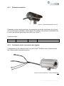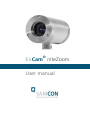
1
® ExCam niteZoom User manual Content 1 Document overview ................................................................................................. 4 2 Technical Data .......................................................................................................... 5 2.1 2.2 2.3 2.4 2.5 2.6 2.7 2.8 Parameters of the explosion protection ............................................................... 5 Electrical parameters........................................................................................... 5 System cable SKAxx ........................................................................................... 5 Mechanical parameters ....................................................................................... 6 Temperature range.............................................................................................. 6 Sensor ................................................................................................................. 6 Lens .................................................................................................................... 7 Electronical functions .......................................................................................... 7 3 Safety guidelines ...................................................................................................... 8 4 Illustration of the model key .................................................................................... 8 5 Commissioning ........................................................................................................ 9 5.1 5.2 Step 1: Installation ............................................................................................... 9 Step 2: Electrical connection ............................................................................. 10 5.2.1 5.2.2 5.2.3 5.2.4 Potential equalization ............................................................................................................... 11 Termination of the connection cable (pigtail) ........................................................................... 11 Power supply & protection ....................................................................................................... 13 Power supply & protection of the camera’s power circuit ........................................................ 13 5.2.4.1 5.2.5 5.2.6 5.2.7 5.3 5.3.1 5.3.2 Power supply & protection of the heating’s power circuit (optional) .............................................. 13 Video picture connection (CVBS) ............................................................................................ 14 Control interface (RS-422) ....................................................................................................... 14 Tests prior to switching on voltage .......................................................................................... 15 Step 3: Adjusting the picture ............................................................................. 15 Work preparation ..................................................................................................................... 18 Opening the pressure-resistant housing .................................................................................. 18 6 Maintenance / Servicing / Alterations ................................................................... 19 7 Repairs and Maintenance ...................................................................................... 19 8 Disposal / Recycling .............................................................................................. 19 9 Drawings ................................................................................................................. 20 10 Notes ....................................................................................................................... 21 Doc.-ID: 131106-PT03BA-SS-ExCam niteZoom_en_rev.01, page 2 of 24 Table of figures Figure 1.1 Document overview .......................................................................................... 4 Figure 5.1 Potential equalization T03-VA… ..................................................................... 11 Figure 5.2 ExCam niteZoom – T03-VA-B-XXX-K-N ........................................................ 11 Figure 5.3 ExCam niteZoom – T03-VA-B-XXX-K-L ......................................................... 12 Figure 5.4 ExCam niteZoom – T03-VA-B-XXX-P-N ........................................................ 12 Figure 5.5 ExCam niteZoom – T03-VA-B-XXX-P-L ......................................................... 12 Figure 5.6 Setting the Baud-transmission rate................................................................. 15 Figure 5.7 FCB Control Panel of the ExCam niteZoom ................................................... 16 Figure 5.8 Control and visualization via a video server ................................................... 16 Figure 5.9 ExCam® niteZoom – lens and sensor board ................................................... 17 Figure 9.1 T03-VA-K1 ...................................................................................................... 20 Figure 9.2 T03-VA-K2 ...................................................................................................... 20 Revision history ExCam® niteZoom User manual for the ExCam® niteZoom 131106-PT03BA-SS-ExCam niteZoom_en_rev.01 Dipl.-Ing. S. Seibert November 06, 2013 Product: Title: Doc. -Id. Author: Date: Rev.-Index Date Name Comments 00 Nov 06, 2013 S. Seibert Compilation of the document Authorization of the ATEX Supervisor Tested and approved Nov 7, 2013 – S. Seibert 01 Aug 08, 2014 T. Gruber Revision and correction Tested and approved Aug 19, 2014 – S. Seibert Doc.-ID: 131106-PT03BA-SS-ExCam niteZoom_en_rev.01, page 3 of 24 1 Document overview T03 ExCam Series: T08 ExCam Series: (ATEX) (ATEX/ IECEx, Bergbau) - EX Installation Manual - EC Declaration of Conformity - EC Type Examination ExCam vario: - User Manual - Datasheet ExCam miniZoom: - User Manual - Datasheet ExCam niteZoom: - User Manual - Datasheet ExCam IP: - User Manual - Datasheet ExCam HD: - User Manual - Datasheet - EX Installation Manual - EC Declaration of Conformity - EC Type Examination ExCam vario: - User Manual - Datasheet ExCam miniZoom: - User Manual - Datasheet ExCam niteZoom: - User Manual - Datasheet ExCam IP: - User Manual - Datasheet ExCam IP1354: - User Manual - Datasheet ExCam IP1355: - User Manual - Datasheet ExCam IPQ1755: - User Manual - Datasheet Figure 1.1 Document overview The present document is marked in red. Doc.-ID: 131106-PT03BA-SS-ExCam niteZoom_en_rev.01, page 4 of 24 2 Technical Data 2.1 Parameters of the explosion protection Identification marks according to Directive 94/9/EG: Explosion protection (gas): II 2G (zone 1 and 2) II 2D (zone 21 and 22) Explosion protection (dust): Ex d IIC T6 Gb or Ex d IIB T6 Gb Ex t IIIC T80°C Db IP67 EC-type examination: Inspection record: Allowed ambient temperature: TÜV 09 ATEX 7697 X 194/Ex.697.00/09 -20° C … +50° C 2.2 Electrical parameters Camera: Supply voltage: Reference power: Power input: Maximum power input: +12 VDC to +30VDC +24 VDC 270 mA to 540 mA 6.5 W (without heating) Heating (optional): Supply voltage: Reference power: Power input: Maximum power input (-20°C): +12 VDC to +24 VDC +24 VDC ca. 1000 mA 10 Watt 2.3 System cable SKAxx Outer diameter: Max. bending radius: Material outer sheath: Color outer sheath: Video: RS 422: Supply voltage camera: Supply voltage heating: 9.4 mm 150 mm PUR – flame retardant according to IEC 60322-1-2 RAL 9005 matt 1 x 75 Ω Koax, 19 x 0.127 mm tinned AWG 24, plated copper braid, shielded 2 x 2 x 0.25 mm2 (twisted pair) Cu shielded double wrapping foil 2 x 0.75 mm2, polyolefine insulated 2 x 0.75 mm2, polyolefine insulated Doc.-ID: 131106-PT03BA-SS-ExCam niteZoom_en_rev.01, page 5 of 24 2.4 Mechanical parameters Housing material: Glass material: Protection level: Stainless steel 1.4301 (AISI 304) and Stainless steel 1.4305 (AISI 303) Optional: Stainless steel 1.4401 (AISI 316) or Stainless steel 1.4404 (AISI 316L) Borosilicate IP 67 (IEC / EN 60529) Weight T03-VA: With K1 flange: With K2 flange: ca. 2,000 g ca. 2,500 g Dimensions T03-VA [WxHxD]: K1 flange, without pin and cable gland: K1 flange, with pin and cable gland: K2 flange, without pin and cable gland: K2 flange, with pin and cable gland: 79 x 79 x 128 [mm] 79 x 96 x 128 [mm] 79 x 79 x 141 [mm] 79 x 96 x 141 [mm] Fitting of the flame proof gap Preventing the transmission of ignition (cylinder) T03-VA…: 2.5 Nominal diameter: 57 mm ISO fit: H8 f7 Temperature range T03-VA-X-XXX-X-N (without heating): 0° C to +50° C T03-VA-X-XXX-X-L (with heating): -20° C to +50° C 2.6 Sensor Sensor: Effective sensor resolution: Horizontal resolution: 1/3‘‘ Super HAD CCD II - technology PAL: 440,000 pixel (ca. 752 x 582) NTSC: 380,000 pixel (ca. 768 x 494) PAL: 530 TV lines NTSC: 530 TV lines Doc.-ID: 131106-PT03BA-SS-ExCam niteZoom_en_rev.01, page 6 of 24 2.7 Lens AF-Zoom lens: Focal distance (f): Angle of view: Aperture: Minimal illumination: Recommended illumination: Minimal object distance: 2.8 10 x optical / 4 x digital 5.1 mm to 51.0 mm 52° (wide) to 5.4° (tele) F1,8 to F2,1 0.0004 lux (1/4 s, 1/3 s mode & ICR on) 100 to 100.000 lux 150 mm (wide) 800 mm (tele) Electronical functions Electronical shutter function Serial control via VISCA/RS-422 Composite video (VBS) video output 1 Vpp Back Light Compensation (BLC) Auto White Balance (ATW) Aperture correction (APC) DSP SNR: ≥50 dB Doc.-ID: 131106-PT03BA-SS-ExCam niteZoom_en_rev.01, page 7 of 24 3 Safety guidelines Please observe the safety guidelines indicated in the ATEX installation manual of the ExCam series! 4 Illustration of the model key The following model options are currently available for the ExCam Product name ExCam niteZoom ® niteZoom: Model option ATEX Type housing (1) option Explosion (2) group Meter (3) SKA02 Cable (4) termin. Housing (5) heating T03T03T03T03T03T03T03T03- VAVAVAVAVAVAVAVA- BBBBCCCC- 005005005005005005005005- KKPPKKPP- N L N L N L N L (1) VA = Execution in stainless steel (2) B = Explosion group IIB (standard - all gases except hydrogen, acetylene, carbon disulphide) C = E Explosion group IIC (all gases) (3) Length of the connection line in meter (001 - 200) (5 meter is the standard length) (4) K = Terminal block connection (standard) All signaling lines are spliced to single strands and furnished with wire-end ferrules to allow connecting the camera to a terminal block P = Plug- termination Approximately 30 cm of the system cable’s outer stealth is stripped. The power supply strands (RD, BK) are furnished with wire-end ferrules. The AWG24 cable is furnished with a BNC connector (5) N = Normal Temperature (0° C – 50° C) L = Low Temperature (-20° C – 50° C) Doc.-ID: 131106-PT03BA-SS-ExCam niteZoom_en_rev.01, page 8 of 24 5 Commissioning Attention! Please observe the national regulations regarding security, installation, and accident prevention (e.g. DIN EN 60079-14) as well as the safety guidelines described in this user manual and the ATEX installation manual! Attention! Please observe the installation and commissioning advices described in the ATEX installation manual! 5.1 Step 1: Installation Install the ExCam® niteZoom at the desired location. Mounting options, accessories, as well as safety guidelines are described in the ATEX installation manual of the ExCam® Series. Attention! Please observe the national regulations regarding security, installation, and accident prevention (e.g. DIN EN 60079-14) as well as the safety guidelines described in this user manual and the ATEX installation manual! Attention! Please observe the installation and commissioning advices described in the ATEX installation manual! Warning! When the iris is open, the camera must not be directed toward the sun as this can cause damages to the sensor. Doc.-ID: 131106-PT03BA-SS-ExCam niteZoom_en_rev.01, page 9 of 24 5.2 Step 2: Electrical connection Attention! The electrical connection of the equipment must be executed by qualified personnel only! Attention! It is mandatory that the housing of the ExCam® Series has to be grounded via a PE-connection! Attention! The minimum cable length of the connection line must not be less than one meter! The connection cable has to be laid in a protected manner! Attention! Please observe the national regulations regarding security, installation, and accident prevention (e.g. DIN EN 60079-14), as well as the safety guidelines described in this user manual and the ATEX installation manual! The ExCam® niteZoom is delivered with an electrical connection cable type SKAxx (System Kabel Analog). The maximum cable length is 200 m and can be determined individually to reflect the particular customer specifications. The minimum cable length is 1 meter. The ExCam® niteZoom is manufactured with a pigtail reflecting the desired cable length. Any electrical work inside the camera’s flameproof enclosure, done by the user, is prohibited. Depending on the model option, the ending of the camera’s cable connection is either stripped and furnished with wire-end ferrules or furnished with a BNC connector. Doc.-ID: 131106-PT03BA-SS-ExCam niteZoom_en_rev.01, page 10 of 24 5.2.1 Potential equalization Figure 5.1 Potential equalization T03-VA… Depending on the housing execution, the equipment’s potential equalization is to be carried out at the place indicated in above figure. The profile of the potential equalization has to reflect the national grounding instructions (min. 4 mm2). Connection table: Potential PA 5.2.2 Color (IEC 60757) GN/YE Profile 2 4 mm (fix) Comments Termination of the connection cable (pigtail) Corresponding to the selected model key, the ExCam ® niteZoom can be delivered with the following cable termination options: Figure 5.2 ExCam niteZoom – T03-VA-B-XXX-K-N Doc.-ID: 131106-PT03BA-SS-ExCam niteZoom_en_rev.01, page 11 of 24 Figure 5.3 ExCam niteZoom – T03-VA-B-XXX-K-L Figure 5.4 ExCam niteZoom – T03-VA-B-XXX-P-N Figure 5.5 ExCam niteZoom – T03-VA-B-XXX-P-L Doc.-ID: 131106-PT03BA-SS-ExCam niteZoom_en_rev.01, page 12 of 24 5.2.3 Power supply & protection 5.2.4 Power supply & protection of the camera’s power circuit The power supply is to be carried out via the red (RD) as well as black (BK) strand. Connection table: Potential L+ L- Color (IEC 60757) RD BK Potential level +12 VDC…+30 VDC 0 VDC Profile 2 0.75 mm 2 0.75 mm Comments The camera’s maximum power consumption is 6.5 Watt. The dimensioning of the equipment or the supply protection depends on: - The selected power supply The cable length The national regulations The following safety recommendations may serve as a basis: Supplied power 12 VDC 24 VDC Length system cable < 200 m < 200 m Recommended protection mT500mA mT200mA Comments The release current of the protection has to be less than the maximum short-circuit current of the power supply (switch-mode power supply)! 5.2.4.1 Power supply & protection of the heating’s power circuit (optional) The power supply is to be carried out via the grey (GY) as well as the white (WH) strand. Connection table: Potential V+ V- Color (IEC 60757) GY WH Potential level +12 VDC…+24 VDC 0 VDC Profile 2 0.75 mm 2 0.75 mm Comments The heating’s maximum power consumption is 10.0 Watt. Doc.-ID: 131106-PT03BA-SS-ExCam niteZoom_en_rev.01, page 13 of 24 The dimensioning of the equipment or the supply protection depends on: - The selected power supply The cable length The national regulations The following safety recommendations may serve as a basis: Supplied power 24 VDC Length system cable < 200 m Recommended protection mT650mA Comments The release current of the protection has to be less than the maximum short-circuit current of the power supply (switch-mode power supply)! 5.2.5 Video picture connection (CVBS) Depending on the model key, the video signal of the ExCam ® niteZoom is either provided with wire-end (K option) or with a BNC connector (P option). The CVBS signal is only to be connected with the monitor, the video matrix, or the video server. Connection table (T03-VA-B-XXX-K-L) Potential Color (IEC 60757) FBAS+ FBAS_GND Potential level WH/ BU BU Profile 1.0 Vp-p (sync negative) 0V Comments 2 0.5 mm 2 2.7 mm Connection table (T03-VA-B-XXX-P-L) Potential FBAS+ Color (IEC 60757) Center (Pin) Potential level 1.0 Vp-p (sync negative) FBAS_GND Shield (bayonet cap) 0V 5.2.6 Profile Comments AWG24 Control interface (RS-422) Potential (Connection at the control board, video server, converter etc.) TxA TxB RxA RxB Potential (ExCam niteZoom) Color (IEC 60757) Profile Comments RxA RxB TxA TxB BN YE GN OG 0.25 mm 2 0.25 mm 2 0.25 mm 2 0.25 mm 2 Doc.-ID: 131106-PT03BA-SS-ExCam niteZoom_en_rev.01, page 14 of 24 5.2.7 Tests prior to switching on voltage Attention! Prior to commissioning, all tests as indicated by the national regulations have to be executed. In addition, it is mandatory that the proper functioning of the operating device in accordance with this user manual and all other applicable regulation has been executed. Attention! Incorrect installation and operation of the camera may lead to a loss of warranty! 5.3 Step 3: Adjusting the picture Adjustment and optimization of the camera picture such as angle of view, zoom, focus, back light compensation, or IR cut filter are exclusively carried out electronically via the camera’s control interface. Mechanical settings at the camera’s block module (Sony FCB-EX20DP) are neither necessary nor allowed! For example, control functions can either be operated manually by the means of a Control Board which has a serial interface (RS-422) and which supports the VISCA protocol (EVI-D70/D70P) or interactively via the web interface of a video server (figure 5.8) or the FCB Control Panel (figure 5.7). The transmission rate of the sending and the receiving end has to be synchronous (figure 5.6). Figure 5.6 Setting the Baud-transmission rate Doc.-ID: 131106-PT03BA-SS-ExCam niteZoom_en_rev.01, page 15 of 24 Figure 5.7 FCB Control Panel of the ExCam niteZoom Figure 5.8 Control and visualization via a video server Doc.-ID: 131106-PT03BA-SS-ExCam niteZoom_en_rev.01, page 16 of 24 Technical data Sony FCB-EX20DP: ® Figure 5.9 ExCam niteZoom – lens and sensor board Lens type Lens Digital zoom Sensor Focal distance Horizontally angle of view Effective pixel count Shutter time Shutter time Minimal illumination Recommended illumination Synchronisation system MOD (Min. Object Distance) Motorzoom 10x optical zoom f=5.1 mm (wide) to 51 mm (tele) (F1.8 to F2.1) 12x (120x with optical zoom) 1/3“-Super-HAD-CCD II 5.1 mm – 51.0 mm 52.0° (wide) – 5.4° (tele) 440,000 1/1 to 1/10000 s (22 steps) 16 steps 0.25 lux (F1.8, ICR off, 150 s) 100 … 100000 lux Internal/ external (V-Lock) 0.01 m (wide end) to 0.8 m (tele end), 0.15 m (standard) Information! If not determined differently, the default setting of the ExCam® niteZoom is wide angle. This means that after the camera has been disconnected from the power supply and has been rebooted, it is set to wide angle mode and standard focus (auto functions are disabled). In case that the ExCam niteZoom is supposed to resume certain settings after the reboot, it is possible to configure „PRESETS“ via the FCB Control Panel, the video server or the VISCA Control Board. Doc.-ID: 131106-PT03BA-SS-ExCam niteZoom_en_rev.01, page 17 of 24 5.3.1 Work preparation Attention! Please carry out any preoperational work carefully and in accordance with the applicable regulations. Note: Depending on the zone classification (DIN EN 60079-10), it might be necessary to obtain a work permit/clearance! When adjusting the camera settings potentially explosive atmosphere must be avoided by any means! 5.3.2 Opening the pressure-resistant housing Opening the pressure resistance housing is not permitted. Any maintenance or repair work must only be carried out by the manufacturer. In case of noncompliance, ATEX certification is voided and any claim under guarantee expires. Doc.-ID: 131106-PT03BA-SS-ExCam niteZoom_en_rev.01, page 18 of 24 6 Maintenance / Servicing / Alterations The national regulations concerning the maintenance and servicing of electrical devices within hazardous areas are to be observed. The required maintenance intervals are specific to the individual devices. The operating company has to determine these intervals depending on the application parameters. During maintenance, focus has to be put on checking parts concerning the ignition protection category such as the integrity of the housing, the sealings and the cable glands. If maintenance measures are necessary they have to be initiated and/or executed. 7 Repairs and Maintenance Repairs must only be carried out with original parts of SAMCON Prozessleittechnik GmbH. Damaged pressure-resistant housings have to be replaced completely. If in doubt, return the applicable part to SAMCON Prozessleittechnik GmbH. Repairs concerning the explosion protection must only be carried out by SAMCON Prozessleittechnik GmbH or a qualified electrical technician authorized by SAMCON Prozessleittechnik GmbH in accordance with nationally applied regulations. Rebuilding of or alterations to the devices are not permitted. 8 Disposal / Recycling When disposing of the device, nationally applicable regulations must be observed. This Document is subject to alterations and additions. Doc.-ID: 131106-PT03BA-SS-ExCam niteZoom_en_rev.01, page 19 of 24 9 Drawings Figure 9.1 T03-VA-K1 Figure 9.2 T03-VA-K2 Doc.-ID: 131106-PT03BA-SS-ExCam niteZoom_en_rev.01, page 20 of 24 10 Notes Doc.-ID: 131106-PT03BA-SS-ExCam niteZoom_en_rev.01, page 21 of 24 Doc.-ID: 131106-PT03BA-SS-ExCam niteZoom_en_rev.01, page 22 of 24 Doc.-ID: 131106-PT03BA-SS-ExCam niteZoom_en_rev.01, page 23 of 24 Schillerstrasse 17, 35102 Lohra-Altenvers www.samcon.eu, [email protected] fon: +49 6426 9231-0, fax: - 31 Doc.-ID: 131106-PT03BA-SS-ExCam niteZoom_en_rev.01, page 24 of 24