1
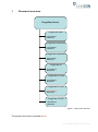
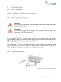
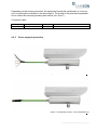
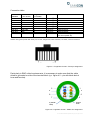
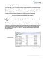
ToughCam IP1355 ® User manual Content 1 Document overview ................................................................................................. 4 2 Technical Data .......................................................................................................... 5 2.1 2.2 2.3 2.4 2.5 2.6 2.7 2.8 2.9 Electrical parameters........................................................................................... 5 System cable SKDxx: .......................................................................................... 5 Sensor ................................................................................................................. 5 Processor ............................................................................................................ 5 Lens .................................................................................................................... 6 Streaming ............................................................................................................ 6 Parameterization ................................................................................................. 7 Network ............................................................................................................... 7 Other technical data ............................................................................................ 8 3 Illustration of the model key .................................................................................... 9 4 Commissioning ...................................................................................................... 10 4.1 4.2 4.2.1 4.2.2 4.2.3 4.3 4.4 4.4.1 4.4.2 4.4.3 4.4.4 4.4.5 5 Step 1: Installation ............................................................................................. 10 Step 2: Electrical connection ............................................................................. 10 Potential equalization ............................................................................................................... 10 Power supply & protection ....................................................................................................... 11 Tests prior to switching on voltage .......................................................................................... 14 Testing of the status LED .................................................................................. 14 Step 3: Adjusting the picture ............................................................................. 15 Work preparation ..................................................................................................................... 16 Opening the housing ................................................................................................................ 16 Adjusting the focus .................................................................................................................. 18 Extracting/inserting an SD storage card .................................................................................. 19 Closing of the housing ............................................................................................................. 20 Network access and visualization ........................................................................ 21 5.1 5.2 5.3 Browser support ................................................................................................ 21 Assigning the IP address ................................................................................... 22 Password / identification .................................................................................... 23 6 Maintenance / Servicing / Alterations ................................................................... 24 7 Repairs and Maintenance ...................................................................................... 24 8 Disposal / Recycling .............................................................................................. 24 9 Drawings ................................................................................................................. 25 10 Notes ....................................................................................................................... 26 Doc.-ID: 140521-PT03BA-TG-ToughCam IP1355_en_rev.01, page 2 of 28 Table of Figures Figure 1.1 Document overview .......................................................................................... 4 Figure 4.1 Potential equalization T03-VA2 ...................................................................... 10 Figure 4.2 ToughCam IP1355 – T03-VA2-B-XXX-K-N .................................................... 11 Figure 4.3 ToughCam IP1355 – T03-VA2-B-XXX-P-N .................................................... 11 Figure 4.4 ToughCam IP1355 – RJ45 pin assignment .................................................... 13 Figure 4.5 ToughCam IP1355 – SKDxx Pin assignment ................................................. 13 Figure 4.6 Opening of the VA2 housing (1) ..................................................................... 16 Figure 4.7 Opening of the VA2 housing (2) ..................................................................... 17 Figure 4.8 Mounting adapter with lens ............................................................................. 18 Figure 4.9 Mechanical adjustments at the lens................................................................ 19 Figure 4.10 MicroSD card slot ......................................................................................... 19 Figure 5.1 Axis IP Utility .................................................................................................. 22 Revision history Product: Title: Doc. -Id. Author: Date: ToughCam® IP1355 User manual ToughCam® IP1355 140521-PT03BA-TG-ToughCam IP1355_en_rev.01 Thiemo Gruber May 21, 2014 Rev.- Index 00 Date May 21, 2014 Name T. Gruber Comments Compilation of the document 01 Aug 27, 2014 T. Gruber Revision Doc.-ID: 140521-PT03BA-TG-ToughCam IP1355_en_rev.01, page 3 of 28 1 Document overview ToughCam Series: ToughCam vario: - User Manual - Datasheet ToughCam miniZoom: - User Manual - Datasheet ToughCam niteZoom: - User Manual - Datasheet ToughCam IP: - User Manual - Datasheet ToughCam IP1354: - User Manual - Datasheet ToughCam IP1355: - User Manual - Datasheet ToughCam IP1357: - User Manual - Datasheet Figure 1.1 Document overview The present document is marked in red. Doc.-ID: 140521-PT03BA-TG-ToughCam IP1355_en_rev.01, page 4 of 28 2 Technical Data 2.1 Electrical parameters Power supply: Reference power: Maximum power input: Maximum input current: 2.2 System cable SKDxx: Outer diameter: Bending radius: Data connection: Characteristics: Interface: 2.3 8.7 ± 0.3 mm 100 mm 4 x 2 x AWG22/1 CAT.6a Halogen free, flame retardant, UV resistant, chemical resistance, shielded (see www.samcon.eu; data sheet SKD01) P version: RJ-45 10BASE-T/100BASE-TX PoE K version: Single Conductor, twisted-pair 10BASE-T/ 100BASE-TX PoE Sensor Type: Effective sensor resolution: Light sensitivity: 2.4 PoE, IEEE 802.3af class 3 (max.12.95 W) or High-PoE (max. 25.5 W) at a cable length of up to 100 m 48 V DC (44...54 V DC) 9.6 W 210 mA 1/2.8‘‘ RGB CMOS, progressive scan 1080p HDTV (1920x1080px / 16:9) Color: 0.2 Lux, F1.2 BW: 0.04 lux, F1.2 Processor Type: Storage: ARTPEC-4 256 MB RAM, 128 MB Flash Doc.-ID: 140521-PT03BA-TG-ToughCam IP1355_en_rev.01, page 5 of 28 2.5 Lens Type: Angle of view: Focus range: Shutter time: P-Iris, varifocus 2.8 – 8 mm, F1.2 IR corrected, CS mount 67°- 39° horizontally, 38° - 22° vertically (16:9) 0.3 m to infinite 1/28000 s to 2 s @50Hz net frequency 1/33500 s to 2 s @60Hz net frequency (Additional lenses for adapting the camera picture to reflect individual and/or environmental requirements as well as compatibility check upon request!) 2.6 Streaming Video compression: Frame rate: Functions: H.264 (MPEG-4 Part 10/AVC), H.264-Profile Baseline and Main, Motion JPEG 25 fps (net freq. 50 Hz) /H.264, Motion JPEG 30 fps (net freq. 60 Hz) /H.264, Motion JPEG Several, individually configurable streams in H.264 and Motion JPEG, controllable frame rate and bandwidth, VBR/ CBR H.264, up to 8 individual clipping viewing areas, event data streaming, edge storage (Network Attached Storage or File-Sever) Doc.-ID: 140521-PT03BA-TG-ToughCam IP1355_en_rev.01, page 6 of 28 2.7 Parameterization Picture settings: Intelligent video: Event trigger: Event actions: Integrated installation: Edge Storage: 2.8 Compression, color, brightness, sharpness, contrast, white balance, exposure control, exposure zones, backlight balance, fine adjustment at low light, WDR – wide dynamic range, picture rotation: 0°, 90°, 180°, 270°, corridor format, picture mirroring, text and picture overlay, private zone masking Video motion recognition, active manipulation alarm Intelligent video, time table and edge storage Data upload: FTP, HTTP, network clearance and e-mail notification: E-mail, HTTP and TCP, pre and post alarm, video buffer, recording on edge storage, PTZ pre-settings, guard tour, day/night switching, status LED activation Focus assistant, fine adjustment of the flange focal distance, pixel counter MicroSD/ microSDHC/ microSDXC internal Card slot for storage card up to 64 GB, video recording at network clearance (NAS, FTP, etc.) Network Security: Supported protocols: Password protection, IP address filter, HTTPS access encryption, IEEE 802.1X network access control, digest authentication, user access protocol IPv4/v6, http, HTTPS, QoS Layer 3 DiffServ, FTP, CIFS/SMB, SMTP, Bonjour, UPnP, SNMPv1/v2c/v3 (MIB-II), DNS, DynDNS, NTP, RTSP, RTP, TCP, UDP, IGMP, RTCP, ICMP, DHCP, ARP, SOCKS Doc.-ID: 140521-PT03BA-TG-ToughCam IP1355_en_rev.01, page 7 of 28 2.9 Other technical data Permissible ambient temperature: -10° C to +50° C Protection level EN 60529/IEC 529: IP 67 Housing material: V2A Stainless steel 1.4301 (standard) or V4A Stainless steel 1.4401 (customized) V4A Stainless steel 1.4404 (customized) Glass material: Borosilicate glass Weight: 5500 g (stainless steel housing T03-VA2.K1) 5900 g (stainless steel housing T03-VA2.K2) Dimensions (L x H x Dmax): 210 mm x 138.5 mm x 113 mm (K1 flange) 226 mm x 138.5 mm x 113 mm (K2 flange) (stainless steel housing T03-VA2 without cable gland, hood, accessory lens etc.) Doc.-ID: 140521-PT03BA-TG-ToughCam IP1355_en_rev.01, page 8 of 28 3 Illustration of the model key The following model options are currently available for the ToughCam IP1355: Product name ToughCam IP1355* Model options ATEX Type Housing (1) option Explosion(2) group Meter (3) SKD01 Cable . (4) termin. Temp. 5) range T03T03T03T03- VA2VA2VA2VA2- 0000- 005005005005- KPKP- N N N N *all model options are available in stainless steel and aluminum housing with K1 or K2 supply flange (q.v. chapter 9 – technical drawings) (1) VA2 = Execution in stainless steel (EN10020 WNr.: 1.4301/1.4305/1.4401/1.4404) (2) 0 = Execution without explosion protection (3) Length of the connection line in meter (001 - 100) (5 meter is the standard length) (4) K = Terminal block connection (standard) The cable insulation is stripped to the twisted-pair strand (ca. 5 cm), including the shield. The individual strands are stripped at the end (ca. 0.5 cm). The fixed Cu inner conductor is blank to allow connecting the camera to the terminal block P = Plug connection The cable is equipped with an RJ-45 network plug (heavy duty), AWG 26-22. Type: Weidmueller IE-PS-RJ45-FH-BK, pin assignment according to T568B (5) N = Normal temperature (-10°C to +50°C) Doc.-ID: 140521-PT03BA-TG-ToughCam IP1355_en_rev.01, page 9 of 28 4 Commissioning 4.1 Step 1: Installation Install the ToughCam ® IP1355 at the desired location. 4.2 Step 2: Electrical connection Attention! The electrical connection of the equipment must be executed by qualified personnel only! Attention! It is mandatory that the housing of the ToughCam® Series has to be grounded via a PE-connection! The ToughCam® IP1355 is delivered with an electrical connection cable type SKDxx (System Kabel Digital). The maximum cable length is 100 m and can be determined individually to reflect the particular customer specifications. The ToughCam ® IP1355 is manufactured with a pigtail reflecting the desired cable length. Depending on the model option, the ending of the camera’s cable connection is either stripped to the blank Cu conductors or furnished with a plug. 4.2.1 Potential equalization Figure 4.1 Potential equalization T03-VA2 Doc.-ID: 140521-PT03BA-TG-ToughCam IP1355_en_rev.01, page 10 of 28 Depending on the housing execution, the equipment’s potential equalization is to be carried out at the place indicated in the above figure. The profile of the potential equalization has to reflect the national grounding instructions (min. 4mm2). Connection table: Potential: PA 4.2.2 Color (IEC 60757) GN/YE Profile 4 mm² (fixed) Comment Power supply & protection Figure 4.2 ToughCam IP1355 – T03-VA2-B-XXX-K-N Figure 4.3 ToughCam IP1355 – T03-VA2-B-XXX-P-N Doc.-ID: 140521-PT03BA-TG-ToughCam IP1355_en_rev.01, page 11 of 28 The green patch cable SKDxx disposes of 8 conductors used for the data transfer with other network devices as well as to power the camera. In order to guarantee the power supply of the ToughCam IP1355, a PoE (Power over Ethernet) capable component has to be available (e.g. a PoE Switch, a PoE Injector, or Midspan) which meets the specification IEEE 802.3af of the power class 3 (6.49– 12.95W/ 26-30mA). An 100 Mbit Ethernet Connection (100BASE-TX) is used for the ToughCam IP1355‘s data transfer. In case the camera disposes of a plug, (figure 4.3) it has to be plugged into the associated slot of the network device. Due to the design, a faulty connection or pin assignment is not possible. The network device can already be supplied with power, prior to connecting it to the camera, hence there is no „power ON“ priority which has to be observed. It is also allowed to separate and re-connect the ToughCam IP1355 from the network when in operation or when interacting with the visualization software (hot plugging). If the ToughCam IP1355’s pigtail has a single conductor termination (figure 4.2) it is mandatory to observe the correct pin assignment on the terminal block. To do so, the potentials of the ToughCam IP1355 have to be connected to the corresponding conductors of the network device. Hence the conductors of the twisted pair cable have to be connected to the conductors with identical color code. The pin assignment of the SKDxx is in accordance with the standard EIA/TIA-568B for 100 BaseTX with PoE according to 802.3af and is executed as follows: Doc.-ID: 140521-PT03BA-TG-ToughCam IP1355_en_rev.01, page 12 of 28 Connection table: Pin/ Potential Tx+ TxRx+ PoE 48 VDC PoE 48 VDC RxPoE Gnd PoE Gnd Shield/ GND Color (IEC 60757) WS / OR OR WS / GN BL WS / BL GN WS / BR BR SW Plug contact (TIA-568B) 1 2 3 4 5 6 7 8 0 Profile Comments 2 0.64 mm 2 0.64 mm 2 0.64 mm 2 0.64 mm 2 0.64 mm 2 0.64 mm 2 0.64 mm 2 0.64 mm NA Solid Conductor Solid Conductor Solid Conductor Solid Conductor Solid Conductor Solid Conductor Solid Conductor Solid Conductor Braids of tinned copper wire p=0.13mm (AWG 36) Sheath: PUR, green (similar RAL 6018), QA=8.7 mm, halogen free, flame retardant, UV stable, chemical resistance Figure 4.4 ToughCam IP1355 – RJ45 pin assignment Particularly in EMC critical environments, it is necessary to make sure that the cable shield is grounded on side of the terminal block (q.v. figure 4.2 – pin with black shrink hose and ferrules). 5 1 4 2 8 6 7 0 (Shield/ GND) 3 Shield/ GND Figure 4.5 ToughCam IP1355 – SKDxx Pin assignment Doc.-ID: 140521-PT03BA-TG-ToughCam IP1355_en_rev.01, page 13 of 28 In case the ToughCam IP1355 is supplied via a PoE capable device, an additional safeguarding of the power supply is not necessary. The power supply is executed by the PoE network device via an electronic with intelligent set-up. The camera as well as the connection is permanently monitored in order to avoid any failure or defects in case of a short-circuit fault. In case of a separate 48 V DC power supply (non-PoE/self-sustaining), an adequate supply safeguarding has to be dimensioned. Recommended is a medium time lag fuse 300 mA. 4.2.3 Tests prior to switching on voltage Attention! Prior to commissioning, all tests as indicated by the national regulations have to be executed. In addition, it is mandatory that the proper functioning of the operating device in accordance with this user manual and all other applicable regulation has been executed. Attention! Incorrect installation and operation of the camera may lead to a loss of warranty! 4.3 Testing of the status LED Through the sight glass, the status LED is visible. Prior to accessing the camera via the web interface, the proper functioning of the camera should be tested. The booting process of the ToughCam IP1355 can take up to one minute. Additional LEDs for checking network activities or the bandwidth are only visible when the housing is open. The status of the network camera as reflected by the LED indicators is as follows: Doc.-ID: 140521-PT03BA-TG-ToughCam IP1355_en_rev.01, page 14 of 28 Status LED Operation mode Color Green Yellow Usage of the focus assistant Red Color Green Yellow Red 4.4 Comment At normal operation, a constant green light shows Note: It is possible to configure the status LED in such a manner that in normal operation it is not illuminated or only blinks when the camera is accessed It is illuminated permanently when the camera is turned on as well as when the camera is set back to default settings In case of an activation failure the light blinks slowly Comment Focus assistant is activated. The lens is set to optimum The camera was moved or an object was placed in front of the lens. Complete the focus assistant and restart it. The lens was not set to optimum The camera was moved or an object was placed in front of the lens. Complete the focus assistant and restart it. The lens was set insufficiently Step 3: Adjusting the picture This step is only required in case the default settings of the picture do not deliver the desired results. If so, the focus as well as the angle of view (tele) has to be readjusted. Lens data: Lens type Lens Aspherical technology Focal distance Horizontal angle of view* Iris control MOD (Min. Object Distance) Varifocal, IR-correction, CS mount F1.2, 2.8 – 8 mm, P-Iris No 2.8 – 8 mm 109° (wide) – 39° (tele) Yes / accuracy automatic 0.30 m *Image angle deviating (q.v. chapter 2.5 Lens) Information! If not determined differently, the default setting for the ToughCam ® IP1355 is set to a 16:9 picture size (1920x1080). The focus was optimized for a distance of approximately 10m. If desired, we customize the ToughCam® IP1355 settings to reflect specific picture sizes (16:10, 16:9, 4:3) and object distances. Please advise accordingly at order placement. Doc.-ID: 140521-PT03BA-TG-ToughCam IP1355_en_rev.01, page 15 of 28 4.4.1 Work preparation Attention! Please carry out any preoperational work carefully and in accordance with the applicable regulations. Attention: Note: Depending on the zone classification, it might be necessary to obtain a work permit/clearance! When adjusting the camera settings potentially explosive atmosphere must be avoided by any means! Please consider that in order to carry out the applicable settings, a feedback regarding the picture quality is required. Please use appropriate devices (laptop, CCTV tester, walkie-talkie to the control room) 4.4.2 Use appropriate tools Make sure you have a secure foothold Avoid static charge Opening the housing In case it is necessary to adjust the picture, the housing has to be opened and after completion of the work securely tightened again. Please be very careful and follow thoroughly the steps of this manual. Stainless steel housing (VA2) Loosen the four hexagon socket screws (DIN-912) located at the cable gland flange of the stainless steel housing, including the washer springs. Avoid skin or clothing contact with the screw threads which disposes of LOCTITE (chemical basis: Dimethacrylatester) to secure the screws. It is not allowed to open the sight glass flange. Figure 4.6 Opening of the VA2 housing (1) Doc.-ID: 140521-PT03BA-TG-ToughCam IP1355_en_rev.01, page 16 of 28 Pull out very carefully the lead flange in a straight manner, ensuring that the board module does not tilt. Avoid skin and clothing contact with the cylindrical fit, the surface is treated with lubrication paste (oleaginous). Figure 4.7 Opening of the VA2 housing (2) ATTENTION: Please make sure not to damage housing sealings Doc.-ID: 140521-PT03BA-TG-ToughCam IP1355_en_rev.01, page 17 of 28 4.4.3 Adjusting the focus The default focus of the ToughCam IP1355 network camera is set to a distance of 10 m and usually no adjustment is necessary. In order to focus on objects in lesser or greater distance, or to change the zoom (wide -> tele), please follow the below steps: 1. 2. 3. 4. 5. 6. 7. 8. Via a web browser, please open the user interface of the ToughCam IP1355 (q.v. chapter 5 „web browser access”). Navigate through the „Setup“ menu via the „Basic Setup“ to the „Focus“ settings Below the button „Basic“, please click on “Open iris“. If the button is deactivated (greyed out) the aperture is already open Now click on „Reset“ in order to reset the focal lens to default value Loosen the zoom as well as sharpness control at the lens by turning counterclockwise. Move both controllers and adjust the zoom as well as the sharpness as required. Check the picture quality in the window below Tighten the zoom as well as sharpness control again Within the configuration menu, click afterwards on the button „Fine-tune focus automatically“ and wait until the automatic optimization is completed To activate the aperture again, click on “Enable iris“. If the button is deactivated (greyed out) the aperture is already activated If necessary, additional adjustments can be carried out at the tab „Advanced“ Note: Prior to starting the automatic fine adjustment, adjust the sharpness as precisely as possible by the means of the sharpness control or the focus assistant. The sharpness controller usually provides the best results. Varifocal lens Figure 4.8 Mounting adapter with lens Doc.-ID: 140521-PT03BA-TG-ToughCam IP1355_en_rev.01, page 18 of 28 Sharpness controller Zoom controller Figure 4.9 Mechanical adjustments at the lens 4.4.4 Extracting/inserting an SD storage card The ToughCam IP1355 is delivered with a 16GB microSDHC storage card. Saved video files can be viewed or deleted via the web interface; they are also available in a download list or as an ftp file to the network. If the SD card has to be changed, the new storage card should be blank and preformatted with an „ext4“ or „vFAT“ data system. The SD card slot is located on the bottom side behind the circuit board across the RJ45 connection (q.v. figure 4.10). microSD card slot Figure 4.10 MicroSD card slot Doc.-ID: 140521-PT03BA-TG-ToughCam IP1355_en_rev.01, page 19 of 28 Attention when inserting / extracting the storage card. Do not damage electronic parts or the cable gland! Do not bend the mounting adapter as otherwise the optical axis of the equipment is not guaranteed anymore! When touching electrical components, potential equalization (grounding of the body) has to be observed (carry a PE wristband etc.)! When touching electrical components, potential equalization (grounding of the body) has to be observed (carry a PE wristband etc.)! 4.4.5 Closing of the housing For closing the housing, please follow, in reversed order, the steps described in chapter 4.4.2 (opening the housing). Only use the applicable cylinder head screws M4 x 0.7 A2 (DIN912) and tighten them in crosswise sequence (the thread length is 12 mm at the K1 flange and 30 mm at the K2 flange). Particularly concerning the joint (gap), please work very carefully. Do not lock-in any foreign objects in the housing. Please make sure that the disassembled screw locks (washer spring DIN7980) are reassembled. If, when closing the housing, it is noted that the surface of the joint is dirty or not lubricated sufficiently, please clean it with a clean cloth and suitable cleaning detergent. Afterwards, re-lubricate it with a suitable lubrication agent. Tighten the M 4 x 0.7er flange screws with approx. 3 Nm at a non-lubricated thread. Please avoid extensive tightening – this might lead to a torn screw. Doc.-ID: 140521-PT03BA-TG-ToughCam IP1355_en_rev.01, page 20 of 28 5 Network access and visualization The following steps describe the most important steps for the initial commissioning of the camera. The configuration menu of the web surface allows an intuitive navigation and offers several configuration possibilities. For a comprehensive user manual of the web surface, please refer to the to the Axis user manual which can be found on the provided USB stick or which can be accessed at: http://www.axis.com/de/files/manuals/um_p1355_49956_en_1303.pdf Network access of the ToughCam IP1355 is supported by most operating systems and browsers. The recommended browsers are Internet Explorer with MS Windows, Safari with Macintosh and Firefox with Windows and additional operating systems. To carry out „video streaming“ via the Microsoft Internet Explorer, installing the “AXIS Media Control” (AMC) is required. The installation request is executed during the initial commissioning. In order to visualize the „H.264“ video streams, QuickTimeTM is recommended. For „Motion JPEG“ coded video streams, Java Applet is suggested which requires JVM (J2SE) 1.5 or higher, or JRE (J2SE) 5.0 or higher. At delivery, the ToughCam IP1355 is set to the applicable net frequency (50Hz or 60Hz). If the camera is used at a location with a differing net frequency, a flickering of the picture might be noticeable, particularly in surroundings with fluorescent tubes. In such a case, the applicable settings have to be carried out within the menu “System Options > Advanced > Plain Config”. 5.1 Browser support A list with the currently supported web browsers, operating systems, and required addons can be viewed at: http://www.axis.com/techsup/cam_servers/tech_notes/browsers.htm Doc.-ID: 140521-PT03BA-TG-ToughCam IP1355_en_rev.01, page 21 of 28 5.2 Assigning the IP address The ToughCam IP1355 is an Ethernet network camera requiring an IP address to access it. Usually a DHCP server is integrated in most networks which automatically assigns an IP address. In case there is no DHCP server available in the network, the ToughCam IP1355’s default address “192.168.0.90” (subnet masking 255.255.255.0) is used. With the “AXIS IP Utility“ it is possible to determine the IP address under Windows; the included USB stick contains this application. It is also available for download: http://www.samcon.eu/en/downloads/drivers-software/ In case it is not possible to assign the IP address, it might be necessary to change the firewall settings! The “AXIS IP Utility“ tool automatically recognizes all ToughCam devices and displays them. It can also be used to manually assign a static IP address. Please note that the ToughCam IP1355 network camera has to be installed within the same network segment (physical subnet) as the computer on which the “AXIS IP Utility” tool is executed. It has the network ID „Axis P1355“ (q.v. figure 5.1). The MAC address and the serial number are also displayed. ToughCam IP1355 Figure 5.1 Axis IP Utility Doc.-ID: 140521-PT03BA-TG-ToughCam IP1355_en_rev.01, page 22 of 28 5.3 Password / identification The default user name is: The default password is: root root When a system reset of the equipment has been carried out, please follow the instructions below. In order to allow access to the ToughCam IP1355, the password for the standard administrator user „root“ has to be determined. When accessing the camera for the first time, the dialog field „Configure Root Password“ is displayed and the password can be determined there. For security considerations, it is possible to use an encrypted HTTPS-connection requiring an HTTPS certificate (see steps below). For assigning the password via a standard HTTP connection, please just enter the password directly in the dialog window „Configure Root Password“. For using an encrypted HTTPS connection when determining the password, please follow the below steps: 1. 2. 3. 4. 5. 6. 7. Click on the button „Create self-signed certificate“ Enter the desired information and click „OK“. The certificate is issued and the password can be entered. Please note that the entire data transfer of the ToughCam IP will be encrypted Enter the desired password and repeat it in order to ensure correct spelling. Click on “OK“ to configure that password Enter the username “root“ (it is not possible to change the default administrator user name „root“) Enter the previously determined password and click on „OK“. In case you have forgotten the password, the ToughCam IP1355 has to be reset to default settings Click on „Yes“ in order to install AMC (AXIS Media Control). After the completion of the installation, it is possible to view the video streams with the Microsoft Internet Explorer or Mozilla Firefox (administrator rights are required) The page „Live View“ of the ToughCam IP1355 is now displayed. With the setup link it is possible to open the menu options to allow personal camera settings Doc.-ID: 140521-PT03BA-TG-ToughCam IP1355_en_rev.01, page 23 of 28 6 Maintenance / Servicing / Alterations The required maintenance intervals are specific to the individual devices. The operating company has to determine these intervals depending on the application parameters. During maintenance, focus has to be put on checking parts concerning the IP protection category such as the integrity of the housing, the sealings and the cable glands. If maintenance measures are necessary they have to be initiated and/or executed. 7 Repairs and Maintenance Repairs must only be carried out with original parts of SAMCON Prozessleittechnik GmbH. Repairs must only be carried out by SAMCON Prozessleittechnik GmbH or a qualified electrical technician authorized by SAMCON Prozessleittechnik GmbH in accordance with nationally applied regulations. Rebuilding of or alterations to the devices are not permitted. 8 Disposal / Recycling When disposing of the device, nationally applicable regulations must be observed. This Document is subject to alterations and additions. Doc.-ID: 140521-PT03BA-TG-ToughCam IP1355_en_rev.01, page 24 of 28 9 Drawings T03-VA2-XX (K1) Front view Side view from left T03-VA2-XX (K2) Front view Side view from left Doc.-ID: 140521-PT03BA-TG-ToughCam IP1355_en_rev.01, page 25 of 28 10 Notes Doc.-ID: 140521-PT03BA-TG-ToughCam IP1355_en_rev.01, page 26 of 28 Doc.-ID: 140521-PT03BA-TG-ToughCam IP1355_en_rev.01, page 27 of 28 Schillerstrasse 17, 35102 Lohra-Altenvers www.samcon.eu, [email protected] fon: +49 6426 9231-0, fax: - 31 Doc.-ID: 140521-PT03BA-TG-ToughCam IP1355_en_rev.01, page 28 of 28