1
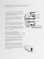
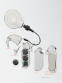
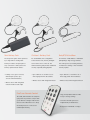
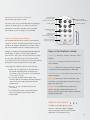
Getting to Know the OPUS 2
The parts and functions
Control Unit: The control unit is just like a tiny computer.
Control Unit
Inside, an electronic chip controls the entire system. It can hold
several different programs (also called ‘maps’), which contain
the specific hearing settings for each user.
Microphone port: This tiny opening is where sound enters
the processor. The microphone is most sensitive to sounds
coming from the front, although it is able to pick up sounds
Microphone port
LED indicator
Locking earhook
On/Off switch
from a wide area.
Battery pack
Locking earhook (optional): The OPUS 2 processor features
an earhook that can be secured to the control unit with a small
pin to prevent young children from removing the earhook.
LED indicator: This small red light indicates a variety of status
and error conditions. It should illuminate when the processor is
first turned on and will indicate which position is currently active
(with 1, 2, 3 or 4 quick blinks).
Microphone cover: This small cover is used
with the BabyBTETM and ActiveWear configurations. It
replaces the earhook for wearing options that are not
worn at the ear and serves to protect the microphone.
Integrated telecoil: The telecoil is located in the OPUS 2
control unit and requires no additional parts or cables. Select
telecoil settings using the FineTuner remote control to reduce
background noise with hearing aid compatible telephones and
induction loop systems.
FM Battery Cover: The standard input jack on the FM
Battery Cover provides the widest variety of connectivity with
different audio devices. The input jack is the same three-pin
port that is used with hearing aids – which allows new CI users
to preserve their initial investments by continuing to use their
personal assistive devices.
4
Coil