1
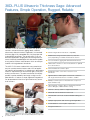
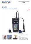
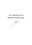
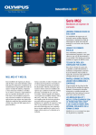
Ultrasonic Thickness Gage
38DL PLUS
38DL PLUS Ultrasonic Thickness Gage
Advanced Features, Simple Operation
• D
ual and Single Element Transducers
• Rugged, designed for IP67
• Thickness range from 0.08 mm (0.003 in.) to 635 mm (25 in.)
• Color Transflective VGA Display
38DL PLUS Ultrasonic Thickness Gage: Advanced
Features, Simple Operation, Rugged, Reliable
The 38DL PLUS is an innovative instrument that signals a
new era in ultrasonic thickness gaging. Ideally suited for
almost every ultrasonic thickness application, this handheld
thickness gage is fully compatible with a full line of dual and
single element transducers. The versatile 38DL PLUS can
be used in applications ranging from wall thinning measurements of internally corroded pipes with dual element probes
to very precise thickness measurements of thin or multilayer
materials with single element transducers.
The 38DL PLUS comes standard with many powerful but
easy-to-use measurement features and a host of application-specific software options. Its sealed case is designed to
meet IP67 requirements to withstand the rigors of very wet
or dusty environments. The color transflective VGA display
provides superior readability from bright sunlight to complete darkness. It features a simple, ergonomic keypad that
can be operated with the left or right hand for easy access
to all functions.
Key Features
■■ Dual and single element transducer compatibility
■■ Wide thickness range: 0.08 mm (0.003 in.) to 635 mm
(25 in.) depending on material and transducer selection
■■ Corrosion thickness gaging with dual element transducers
■■ THRU-COAT® and Echo-to-Echo measurements on painted
and coated surfaces
■■ Internal Oxide/Scale software option
■■ Standard resolution of 0.01 mm or 0.001 in. for all
transducers
■■ High Resolution software option of 0.001 mm or 0.0001 in.
with single element transducers 2.25 MHz to 30 MHz
■■ Multilayer software option for measurements of up to four
layers simultaneously
■■ High Penetration software option for attenuating materials
such as fiberglass, rubber and thick casting
■■ Thickness, Velocity, and time-of-flight measurements
■■ Differential mode and Reduction Rate mode
■■ Time-based B-scan mode; 10,000 reviewable readings per
scan
■■ Olympus High Dynamic Gain technology with digital filters
■■ V-Path Builder for custom V-path compensation
■■ Designed for EN15317
2
Ultrasonic thickness measurements are accurate, reliable, and repeatable. Instant
readings can be achieved from one side of a material, making it unnecessary to cut
up or destroy the part.
What Makes This Thickness Gage Different From Others?
The 38DL PLUS is designed to meet the challenges of demanding applications and built to withstand tough conditions
in the field and on the production floor. Whether you work in
very wet or dusty conditions, cold or hot climates, or bright
or dark areas, the 38DL PLUS can handle any inspection job.
Need an instrument tough enough to tolerate shocks, drops,
and rough handling? The 38DL PLUS with its protective rubber
boot and designed for IP67 rating is your answer.
Built for Tough Environments
• Compact, weighs only 0.814 kg (1.80 lb)
• Rugged, designed for IP67
• Explosive Atmosphere: Safe operation as defined by Class I,
Division 2, Group D, as found in the National Fire Protection
Association Code (NFPA 70), Article 500, and tested using
MIL-STD-810F, Method 511.4, Procedure I.
• Shock tested using MIL-STD-810F, Method 516.5, Procedure I,
6 cycles each axis, 15 g, 11 msec Half sine.
• Vibration tested using MIL-STD-810F, Method 514.5, Procedure I,
Annex C, Figure 6, general exposure: 1 hour each axis.
• Wide operating temperature range
• Protective rubber boot with gage stand
• Color transflective VGA display with indoor and outdoor color settings for superior clarity
Designed for Easy Operation
• Simple keypad for right hand/left hand operation
• Easy operator interface with direct access to all functions
• Internal and External MicroSD memory card storage
• USB and RS-232 communication ports
• Alphanumeric data logger with 475,000 thickness readings
or 20,000 waveforms
• VGA output to connect to computer or monitor
• Default/Custom dual element transducer setups
• Default/Custom single element transducer setups
• Password protected function allows locking of instrument features
Outdoor display setting,  A-scan mode
Indoor display setting,  B-scan mode
38DL PLUS with standard protective rubber boot
3
Thickness Measurements on Internally Corroded Metals
One of the major applications of the 38DL PLUS is measuring the remaining thickness of pipes, tubes, tanks, pressure
vessels, hulls, and other structures affected by corrosion or
erosion. Dual element transducers are most commonly used
for these applications.
• Automatic Probe Recognition for standard D79X series dual
element transducers
• Ten custom dual element transducer setups
• Optimized default gain during calibration for dual element
transducer
• V-Path Builder for custom V-path compensation
• Calibration Doubling warning when echo doubling may occur
during calibration
• THRU-COAT® and Echo-to-Echo measurements on painted
and coated surfaces
• High temperature measurements; up to 500 °C (932 °F)
• Boiler tube and Internal Oxide measurements (optional) with
M2017 or M2091 single element transducers
• EMAT transducer (E110-SB) for no-couplant measurements of
boiler tubes with external oxide/scale buildup
4
Encoded B-scan Option
Thru-Coat® Technology
This powerful optional feature
allows the 38DL PLUS to be
connected to a linear encoded
scanner to generate encoded
B-scans. The 38DL PLUS will
capture and store the distance
traveled information along with
corresponding thickness readings.
The waveform at the minimum
thickness location is also
captured. The user can select the
distance between measurements
and select between bidirectional
and unidirectional modes. Up to
10,000 thickness readings can be
stored in a single B-scan.
uses a single back-wall echo to
measure true metal thickness.
You can display the metal
and coating thicknesses,
each adjusted for their correct
material sound velocities. There
is no need to remove paint and
coatings from surfaces. THRUCOAT® measurements use the
D7906-SM, D7906-RM, and
D7908 dual element transducers.
Temperature Compensation
Oxide/Scale Measurement Option
variations in material temperature
affect sound velocity and
accuracy of thickness
measurements. The temperature
compensation feature allows you
to manually enter the calibration
block’s temperature and the
current (high) temperature at the
measurement points. The 38DL
PLUS automatically displays the
temperature-corrected thickness.
uses advanced algorithms to
measure the thickness of oxide/
scale buildups inside boiler
tubes. The gage simultaneously
displays the metal thickness of
the boiler tube and the thickness
of the oxide layer. Knowing the
thickness of the oxide/scale helps
predict tube life. We recommend
using M2017 or M2091
transducers in this application.
V-Path Builder
This new and patented feature allows you to build a custom
V-Path compensation curve for almost any dual element
transducer. These curves can be saved and recalled along
with custom setups for most dual element transducers.
You simply calibrate and enter the known thickness with
a minimum of 3 and up to 10 calibration points, and the
instrument will create the V-path.
Automatic Probe Recognition
All standard dual element transducers (see chart on the
next page) feature Automatic Probe Recognition, which
automatically recalls a default V-path correction for each
specific transducer.
5
Dual Element Transducers for Corrosion Gaging
All standard dual element transducers feature Automatic Probe Recognition, which automatically recalls a default V-path
correction for each specific transducer.
Transducer
Item
Number
Freq.
(MHz)
D790
U8450002
Straight
Potted
D790-SM
U8450009
Straight
LCMD-316-5B
D790-RL
U8450007
D790-SL
U8450008
5.0
Connector
90°
U8450010
5.0
90°
D791-RM
U8450011
5.0
90°
D792
U8450012
D793
U8450013
U8450014
D797
U8450016
D797-SM
U8450017
D7226
U8454013
D798-LF
U8450019
D798
U8450018
D798-SM
U8450020
10
5.0
2.0
7.5
7.5
Straight
90°
Straight
90°
Straight
90°
90°
Straight
D799
U8450021
5.0
90°
MTD705
U8620225
5.0
90°
D7906-SM††
U8450005
D7906-RM††
U8450025
D7908††
U8450006
11.00
(0.434)
Range (Steel)*
mm (in.)
1.00 to 500.00
(0.040 to 20.000)
Temp. Range**
°C (°F)
–20 to 500
(–5 to 932)
Straight
D791
D794
Tip Dia.
mm (in.)
5.0
7.5
Straight
90°
90°
11.00
(0.434)
11.00
(0.434)
1.00 to 500.00
(0.040 to 20.000)
1.00 to 500.00
(0.040 to 20.000)
–20 to 500
(–5 to 932)
–20 to 400
(–5 to 752)
7.20
(0.283)
0.50 to 25.00
(0.020 to 1.000)
0 to 50
(32 to 122)
7.20
(0.283)
0.75 to 50.00
(0.030 to 2.000)
0 to 50
(32 to 122)
22.90
(0.900)
3.80 to 635.00
(0.150 to 25.000)
–20 to 400
(–5 to 752)
8.90
(0.350)
0.71 to 100.00
(0.028 to 4.000)
–20 to 150
(–5 to 300)
7.20
(0.283)
0.71 to 100.00
(0.028 to 4.000)
–20 to 150
(–5 to 300)
11.00
(0.434)
5.10
(0.200)
1.00 to 500.00
(0.040 to 20.000)
1.00 to 19.00
(0.040 to 0.750)
–20 to 150
(–5 to 300)
0 to 50
(32 to 122)
11.00
(0.434)
1.00 to 50.00
(0.040 to 2.000)
0 to 50
(32 to 122)
7.20
(0.283)
1.00 to 37.00
(0.040 to 1.500)
0 to 50
(32 to 122)
* T
hickness range dependent on material, transducer type, surface conditions, and
temperature. Full range may require Gain Adjust.
** Maximum temperature with intermittent contact only
†
Item
Number
Cable
—
†
U8800353
†
LCLD-316-5G
U8800330
LCLD-316-5H
U8800331
Potted
—
LCMD-316-5C
U8800354
Potted
—
Potted
—
Potted
—
Potted
—
LCMD-316-5D
U8800355
Potted
—
Potted
—
LCMD-316-5J
U8800357
Potted
—
LCLPD-78-5
U8800332
LCMD-316-5L
U8800358
LCMD-316-5N
U8800647
Potted
—
Stainless steel cable available; consult Olympus NDT for details.
Transducers used with THRU-COAT® technology
††
Single Element Transducers for Corrosion Gaging
For a complete list of single element transducers, please consult your local representative or consult our web site
www.olympus-ims.com.
*
**
†
††
6
Transducer
Item
Number
V260-SM
U8411019
Freq.
(MHz)
Connector
Tip Dia.
mm (in.)
Range (Steel)*
mm (in.)
Temp. Range**
°C (°F)
2.00
(0.080)
0.50 to 10.00
(0.020 to 0.400)
0 to 50
(32 to 122)
Straight
15
90°
Cable
Item
Number
LCM-74-4
U8800348
LCM-74-4
U8800348
LCM-74-4
U8800348
V260-RM
U8411018
V260-45
U8411017
M2017
U8415002
20
90°
6.35
(0.250)
Steel 0.50 to 12.00
(0.020 to 0.500)
Oxide 0.25 to 1.25
(0.010 to 0.050)
0 to 50
(32 to 122)
LCM-74-4
U8800348
M2091
U8415018
20
90°
6.35
(0.250)
Steel 0.50 to 12.00
(0.020 to 0.500)
Oxide 0.15 to 1.25
(0.006 to 0.050)
0 to 50
(32 to 122)
LCM-74-4
U8800348
E110-SB
U8471001
—
Straight
28.50
(1.250)
2.00 to 125.00
(0.080 to 5.000)
0 to 80
(32 to 176)
LCB-74-4 and
1/2XA/E110
U8800320
U8767104
45°
Dependent on material, transducer type, surface conditions, and temperature. Full range may require Gain Adjust.
Maximum temperature with intermittent contact only
Stainless steel cable available; consult Olympus NDT for details.
Transducers used with THRU-COAT® technology
D793
D791
D7908
D792/D794
D790-RL
D790
D791-RM
D7226
D790-SL
MTD705
D798-LF
D7906-SM
D790-SM
D799
D798
D797-SM
m2017
m2091
e110-sb
Additional products available at www.olympus-ims.com
Couplants
Calibration Test Blocks
Transducer Cables
Liquid couplant is almost always
necessary to provide acoustic coupling
between the transducer and the test
piece. We offer various types of couplants to suit virtually all applications.
Test blocks are necessary for the calibration of ultrasonic thickness gages
and should be used to maintain and
verify the accuracy, dependability, and
reliability of ultrasonic measurements.
Blocks are held to tighter tolerances
than stated in ASTM E797 code.
Metric test blocks are available.
A wide selection of transducer cables
suitable for all ultrasonic thickness
gaging instrumentation.
• Standard
• Waterproof
• Heavy Duty
-- Teflon
-- Armored PVS Jacket
-- Armored Silicone Jacket
-- Stainless Steel
7
Thickness Measurements on Plastics, Metals,
Composites, Glass, Rubber, Ceramics
When using single element transducers, you can make
accurate thickness measurements on metals, plastics,
composites, glass, ceramics, and other materials. These
transducers are available in a wide range of frequencies,
diameters, and connector styles. The High Resolution software option allows you to make very precise measurements
at a resolution of 0.0001 in. or 0.001 mm.
• Standard resolution of 0.01 mm (0.001 in.) for all transducers
• High Resolution software option can display measurements up
to 0.001 mm (0.0001 in.) for single element transducers from
2.25 MHz to 30 MHz
• High Penetration software option for measurements on attenuating materials such as fiberglass, rubber, and thick castings
• Multilayer software option for individual thickness measurements of up to four layers simultaneously
• Thickness, Velocity, or time-of-flight measurements
• Application Auto-Recall with default and custom setups to
simplify thickness measurements
Measure the thickness of many materials including plastic, metal, rubber, glass,
ceramic, and composites.
High Penetration Software Option
This option allows you to use low frequency single element
transducers (as low as 0.5 MHz) to measure thick or sound
attenuating materials such as rubber, fiberglass, castings,
and composites.
Multilayer Software Option
This software option calculates and simultaneously displays
thickness measurements of up to four individual layers. It
also displays total thickness of selected layers. Typical applications include thickness of barrier layers in plastic fuel
tanks, bottle preforms, and soft contact lenses.
Outer
Surface
Inside
Surface
Many cast metal parts or sound-attenuating materials can be measured with the
High Penetration software option.
HDPE
Layer
0.1658 in.
EVOH
Barrier
HDPE
Layer
0.0044 in. 0.0781 in.
Total
Thickness
0.2483 in.
The 38DL PLUS can make accurate measurements of up to four individual layers
simultaneously.
8
The High Resolution software option allows thickness measurements of up to 0.001 mm (0.0001 in.) resolution.
Data Logger and PC Interface
The 38DL PLUS has a full-featured internal bidirectional
alphanumeric data logger that is designed to easily collect
and transfer thickness readings and waveform data.
• Internal memory of 475,000 thickness readings or 20,000
waveforms with thickness readings
• 32 Character File name
• 20 Character ID# (TML#)
• 9 file formats:
Incremental, Sequential, Sequential with custom point, 2-D
Grid, 2-D Grid with custom point, 3-D Grid, 3-D custom,
Boiler, and Manual
• The ability to store up to 4 comments (notes) per ID# (TML)
• Stores comments (notes) at an ID# or to a Range of ID#’s
• Internal and External MicroSD memory cards
• File copy with the ability to copy files between Internal/External
MicroSD memory cards
• Standard USB and RS-232 communication
• Two-way transfer of both single and dual element transducer
setups
• Onboard statistical report
• Onboard DB Grid View with three programmable colors
• GageView™ interface program can communicate with the 38DL
PLUS using the USB, RS-232 ports, and can read and write to
a MicroSD memory card.
• Direct export of internal files to MicroSD memory card in Excel
compatible CSV (comma-separated values) format
MicroSD Card
VGA Connectors
USB Connector
USB or RS-232
Charger
Probe Connectors
Onboard DB Grid View with three programmable
colors
GageView™
• The GageView interface program, a Windows-based application, collects, creates, prints, and manages data from the
38DL PLUS.
• Creates datasets and surveys
• Stored data editing
• View dataset and survey files; including thickness readings,
gage setup values, and transducer setup values
• Download and upload thickness surveys to and from the
gages
• Export surveys to spreadsheets and other programs
• Collecting snapshot screens
• Printing reports such as Thickness, Setup Table, Statistics,
and Color Grid
• Upgrading operating software
• Download and upload single and dual element transducer
setup files
• B-scan review
When viewed on your PC a color coded grid easily flags out-of-tolerance thickness
conditions.
Measurement reports
can easily be generated and printed
containing measurements, ID, and other
parameters.
9
Single Element Transducers for
Precision Thickness Measurements
Contact Transducers
Frequency
(MHz)
Element
Diameter
mm
m102-sb
Item
Number
Transducer
inches
0.5
25
1.00
M101-SB*
U8400017
1.0
25
1.00
M102-SB*
U8400018
1.0
13
0.50
M103-SB*
U8400020
2.25
13
0.50
M106-RM
M106-SM
U8400023
U8400025
2.25
13
0.50
M1036
U8400019
5.0
13
0.50
M109-RM
M109-SM
U8400027
U8400028
5.0
6
0.25
M110-RM
M110-SM
M110H-RM**
U8400030
U8400031
U8400029
M112-RM
M112-SM
M112H-RM**
U8400034
U8400035
U8400033
10
6
0.25
10
3
0.125
M1016
U8400015
20
3
0.125
M116-RM
M116-SM
U8400038
U8400039
20
3
0.125
M116H-RM**
U8400037
m1036
m101-sb
m103-sb
m106-sm
m109-sm
m112-sm
m110-rm
m116-sm
m106-rm
m112-rm
m116-rm
m109-rm
m1061
* These transducers can only be used with the High Penetration software option.
** Use with spring loaded holder
Sonopen®
Transducers
The Sonopen transducer has
a replaceable delay line that is
tapered to a small contact area.
This transducer makes reliable thickness measurements
in applications such as turbine
blades and tight radii on plastic
containers.
v260-45
v260-SM
v260-rm
dlp-301
Sonopen – 15 MHz, 3 mm (0.125 in) transducer
Straight Handle
Right Angle Handle
45° Handle
Part
Item
Number
Part
Item
Number
Part
V260-SM
U8411019
V260-RM
U8411018
V260-45
Sonopen – Replaceable
Delay Lines
Tip Diameter
mm
inches
U8411017
2.0
0.080
DLP-3
U8770086
1.5
0.060
DLP-302
U8770088
2.0
0.080
DLP-301†
U8770087
†
Immersion Transducers
Panametrics Microscan immersion transducers are designed
to transmit and receive ultrasound in water. Thickness measurements by immersion technique are often preferred when
the test piece has a complex geometry or in on-line applications. Typical off-line applications include wall thickness
measurements on small diameter plastic or metal tubing,
scanned or rotary measurements and thickness measurements on sharply curved parts. Transducer focusing may be
necessary depending on the application.
RBS-1 Immersion Tank
The RBS-1 immersion tank is designed to simplify ultrasonic
thickness measurements using immersion techniques.
10
Frequency
(MHz)
Item
Number
Item
Number
High temperature delay for use up to 175° C (350° F)
Element Diameter
mm
Part
inches
Transducer
Item
Number
2.25
13
0.50
M306-SU
U8410027
5.0
13
0.50
M309-SU
U8420001
5.0
6
0.25
M310-SU
U8420004
10
6
0.25
M312-SU
U8420008
15
6
0.25
M313-SU
U8420009
20
3
0.125
M316-SU
U8420011
Delay Line Transducers
Microscan delay line transducers provide excellent performance on very thin materials, at elevated temperatures,
or with applications that require a high degree of thickness resolution.
Freq.
(MHz)
Element
Diameter
Transducer
Item
Number
Holder
mm
inches
0.5
25
1.00
M2008*
U8415001
—
2.25
5.0
5.0
5.0
13
13
6
6
0.50
0.50
0.25
0.25
6
0.25
10
6
0.25
10
3
0.125
20
3
0.125
20
20
3
3
0.125
0.125
U8410017
U8410016
U8410001
U8411030
U8410003
U8410004
U8507023
U8410006
U8410007
U8410019
U8410020
U8410018
U8415013
—
—
—
2127
10
M207-RB
M206-RB
M201-RM
M201H-RM
M202-RM
M202-SM
M202H-RM
M203-RM
M203-SM
M208-RM
M208-SM
M208H-RM
M2055**
30
6
0.25
V213-BC-RM**
U8411022
—
Item
Number
m2055
U8770408
—
2127
U8770408
m2008
—
m202
m201
—
2133
—
U8770412
2127
m206-RB
2133
* These transducers can only be used with the High Penetration software option.
** Delay line is not replaceable on these transducers.
m208h
m208
Replaceable Delay Lines
Delay lines function as a protective buffer
between the surface of the test piece and the
transducer element.
Element
Diameter
Part
Item
Number
0.50
DLH-2
0.25
DLH-1
0.125
DLH-3
mm
inches
13
6
3
Maximum Thickness
Measurement Limit*
Delay Line
Steel - Mode 2
Steel - Mode 3
Plastic - Mode 2
mm
inches
mm
inches
mm
inches
U8770062
25
1.0
13
0.5
13
0.5
U8770054
25
1.0
13
0.5
13
0.5
U8770069
13
0.5
5
0.2
5
0.2
* Exact range depends on material sound velocity, transducer frequency, part geometry, and surface
condition.
11
38DL PLUS Specifications*
Standard Package
Measurements
Dual element transducer
measurement mode
Time interval from a precision delay after the excitation pulse to the first echo
THRU-COAT®
measurement
Measurement of true metal and coating thicknesses with a single back-wall
echo (with D7906-SM and D7908 transducers)
Thru-Paint Echo-to-Echo
Time interval between two successive back-wall echoes to eliminate paint or
coating thickness
Single element transducer
measurement modes
Mode 1: Time interval between the excitation pulse and the first back-wall echo
Mode 2: Time interval between the delay line echo and the first back-wall echo
(with delay or immersion transducers)
Mode 3: Time interval between successive back-wall echoes following the first
interface echo after the excitation pulse (with delay line or immersion
transducers)
Oxide: optional
Multilayer mode: optional
Thickness range
.080 mm to 635.00 mm (0.003 in. to 25.000 in.) depending on material,
0
transducer surface conditions, temperature, and selected configuration
Material velocity range
0.508 mm/μs to 13.998 mm/μs (0.020 in./μs to 0.551 in./μs)
Resolution (selectable)
Low: 0.1 mm (0.01 in.)
Standard: 0.01 mm (0.001 in.)
High Resolution (optional): 0.001 mm (0.0001 in.)
Transducer frequency
range
Standard: 2.0 MHz to 30 MHz (–3 dB)
High Penetration (optional): 0.50 MHz to 30 MHz (–3 dB)
General
Operating temperature
range
Keypad
Case
Dimensions (W x H x D)
Weight
Power supply
Battery life, lithium-ion
Standards
–10 °C to 50 °C (14 °F to 122 °F)
Sealed, color-coded keypad with tactile and audible feedback
Impact-resistant and water-resistant, gasketed case with sealed connectors.
Designed for IP67.
Overall: 125 mm x 211 mm x 46 mm (4.92 in. x 8.31 in. x 1.82 in.)
0.814 kg (1.80 lb)
AC/DC adaptor, 24 V; lithium-ion battery 23.760 Wh; or 4 AA auxiliary batteries
Operating time: minimum 12.6 h, 14 h typical, 14.7 h maximum
Fast charge: 2 h to 3 h
Designed for EN15317
• 38DL PLUS digital ultrasonic thickness gage,
AC or battery operation, 50 Hz to 60 Hz
• Kits available with standard dual element
transducers
• Charger/AC adaptor (100 VAC, 115 VAC,
230 VAC)
• Internal data logger
• GageView interface program
• Test block and couplant
• USB cable
• Rubber protective boot with gage stand and
neck strap
• User’s manual
• Measurement features: THRU-COAT®, ThruPaint Echo-to-Echo, EMAT compatibility, Min./
Max. mode, two alarm modes, differential
mode, B-scan, Application Auto-Recall, temperature compensation, Average/Min. mode
Software Options
38DLP-OXIDE (U8147014): Code-activated
Internal Oxide measurement software
38DLP-HR (U8147015): Code-activated High
Resolution measurement software
38DLP-MM (U8147016): Code-activated
Multilayer measurement software
38DLP-HP (U8147017): Code-activated High
Penetration (low frequency) measurement software
38DLP-EBSCAN (U8147018): Encoded
B-scan software
Optional Accessories
38DLP/EW (U8778348): Three-year warranty
Display
Color transflective VGA
display
Liquid crystal display, display area 56.16 mm x 74.88 mm (2.2 in. x 2.95 in.)
Rectification
Full wave, RF, half-wave positive, or half-wave negative
Inputs/Outputs
USB
1.0 client
RS-232
Yes
Memory card
Maximum capacity: 2 GB External MicroSD memory card
Video output
VGA output standard
Internal Data logger
1/2XA/E110 (U8767104): Filter adaptor for
E110‑SB EMAT transducer
38-9F6 (U8840167): RS-232 cable
38-C-USB-IP67 (U8800998): USB cable for
IP67 sealed operation
38DLP/RFS (U8780288): Foot switch, factory
installed
HPV/C (U8780124): Digital caliper for
thickness input for velocity measurements
38DLP-V-CC (U8840172): Cable for digital
caliper
Data logger
The 38DL PLUS identifies, stores, recalls, clears, and transmits thickness
readings, waveform images, and gage configuration information through the
standard RS-232 serial port or USB port.
Capacity
475,000 thickness measurements or 20,000 waveforms with thickness
measurements
File names, IDs, and
comments
32-character file names and 20-character alphanumeric location codes with
four comments per location
File structures
Nine standard or custom application-specific file structures
BSCAN-ENC (U8779522): Encoded B-scan
buggy
Reports
On-gage reporting of summary with statistics, Min./Max. with locations, Min.
review, file comparison, and alarm report
38DLP-ENC-CBC-10 (U8840168): 10 ft
encoder cable
EPLTC-C-VGA-6 (U8840035): VGA output cable
MICROSD-ADP-2GB (U8779307):
2 GB External MicroSD memory card
is ISO 9001 and 14001 certified.
38DL_PLUS_EN_201309 • Printed in the USA • Copyright © 2013 by Olympus NDT.
*All specifications are subject to change without notice.
All brands are trademarks or registered trademarks of their respective owners and third party entities.
www.olympus-ims.com
48 Woerd Avenue, Waltham, MA 02453, USA, Tel.: (1) 781-419-3900
12569 Gulf Freeway, Houston, TX 77034, USA, Tel.: (1) 281-922-9300
For enquiries - contact
www.olympus-ims.com/contact-us
505, boul. du Parc-Technologique, Québec (Québec) G1P 4S9, Tel.: (1) 418-872-1155
1109 78 Ave, Edmonton (Alberta) T6P 1L8
P/N: 920-212-EN Rev. H