1
nova230 for Danfoss
nova230 for Danfoss
User's Manual
7001044003 R1
This manual refers to the latest protocol
EPROM 501159.001 Index. a
and version 1.0 of the parameterising program
230Danf.xls
7001044003 R1
Sauter Systems
1
nova230 for Danfoss
2
7001044003 R1
Sauter Systems
nova230 for Danfoss
0
Table of contents
1
Introduction .............................................................................................................5
2
System structure .....................................................................................................7
3
Connecting the components ..................................................................................9
4
Device settings ......................................................................................................11
4.1 Danfoss frequency converter VLT6000 .............................................................11
4.2 Connecting and setting the RS232/485 converter .............................................13
5
The VLT6000's data points....................................................................................15
6
Generation of data for the AS ...............................................................................19
6.1 Tables ...............................................................................................................19
6.2 Macro control ....................................................................................................21
7
Generation in the FBD editor ................................................................................23
7.1 Generating VLT6000 data points.......................................................................23
7.2 Generating collective alarms .............................................................................23
8
Putting the EYL 230 F130 into operation .............................................................25
9
VLT commissioning software (PC).......................................................................27
10 Monitoring..............................................................................................................29
11 Language settings.................................................................................................33
7001044003 R1
Sauter Systems
3
nova230 for Danfoss
0
Table of contents
Trademarks
Designer
Micrografx Designer
Media Manager
Windows
Microsoft Office 97 Professional
MS Office
Microsoft Access 97
Microsoft Office 2000
Microsoft Word
Acrobat Reader
Pentium
4
7001044003 R1
Trademark of Micrografx, Inc.
Trademark of Micrografx, Inc.
Trademark of Micrografx, Inc.
Trademark of Microsoft Corporation
Trademark of Microsoft Corporation
Trademark of Microsoft Corporation
Trademark of Microsoft Corporation
Trademark of Microsoft Corporation
Trademark of Microsoft Corporation
Adobe Systems Incorporated
Trademark of Intel Corporation
Sauter Systems
nova230 for Danfoss
1
Introduction
1 Introduction
The nova230 is a compact automation station with interface function and belongs to the
EY3600 family of systems.
The nova230 for Danfoss (EYL 230 F130, compact AS Danfoss VLT6000) enables
Danfoss frequency converters of the VLT6000 series to be linked to Sauter's automation
systems.
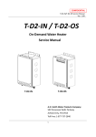
These frequency converters (FCs) are interlinked via an RS485 bus. Up to 31 FCs can
be connected in parallel. By using repeaters, up to 126 FCs can be networked. This
RS485 bus is then connected with the serial output of the EYL 230 via an RS232/RS485
interface converter (e.g. W&T 86201).
The data points for the EYL 230 F130 are generated using an Excel form. All the
necessary operating parameters and data-point information are entered on the form and
then a data record is created; this is transmitted serially to the EYL 230 and held captive
in a non-volatile memory. When the station is re-started, these operating data are read
from the EEPROM and the parameterised data points are polled.
Setpoints and commands are transferred spontaneously to the frequency converters.
Possible data points include operating parameters, status, alarm bits, setpoints and
binary commands.
A possible communication fault between the EYL 230 and the FCs is also provided for
the BMS in an MFA.
To make it easier to put the unit into service, it is possible to log the communication
between the EYL 230 and the FCs on a terminal.
7001044003 R1
Sauter Systems
5
nova230 for Danfoss
1
6
Introduction
7001044003 R1
Sauter Systems
nova230 for Danfoss
2
System structure
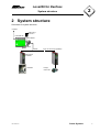
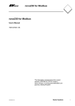
2 System structure
Schematic for system structure.
novaNet
230 V a.c./
12 V a.c.
EYL230F130
WUT 86201
RS232
1
RS485
31 (up to 126 using repeaters)
Danfoss FC
VLT6000
Ventilator
7001044003 R1
Pumps,
motors etc.
Sauter Systems
7
nova230 for Danfoss
2
8
System structure
7001044003 R1
Sauter Systems
nova230 for Danfoss
3
Connecting the components
3 Connecting the components
The following connections should be established between the components:RS232 plug for EYL 230 and RS485 converter
EYL 230
RS-232
Pin 3
Pin 2
Pin 5
RS485 converter
W&T #86201
o-->------------------------------o Pin 2
o--<------------------------------o Pin 3
o---------------------------------o Pin 5
(Din)
(Dout)
(GND)
N.B.: A screening braiding should be fitted on both sides at Pin5 (GND).
W&T86201 converter for the Danfoss VLT6000 (RS485 bus)
RS485 converter
W&T #86201
Danfoss VLT6000
Terminal strip
Pin 1+2
o-------------------------------o Terminal 69
(RS485-N)
Pin 6+7
o-------------------------------o Terminal 68
(RS485-P)
The screening of the RS485 cable should be put to terminal 61.
The terminals of the VLT6000 are identified as per the following table. For an exact
description of the functions, consult the VLT6000's manual.
Terminal identification Terminal
Function
Acknowledge
16
Digital input
Block
17
Operation/Stop
18
Reverse
19
Common GND
20
GND
Lock
27
Fixed speed
29
Parameter-set selector
32
Parameter-set selector
33
+24 V Out
12+13
+24V output
4-20mA Input
60
Current input
0-10 V d.c. setpoint input
53
Setpoint input 1
0-10 V d.c. setpoint input
54
Setpoint input 2
+10 V output
50
Reference output
Three-phase mains input 91+92+93
Mains power supply
Motor outputs
96...99
Three-phase output
Fault indicator
1+2+3
Relay 1 240V/2A
'Power on' indicator
4+5
Relay 2 50V/1A
Output current indicator
42
Analogue value 4-20mA
Output speed indicator
45
Analogue value 4-20mA
GND for analogue values
39
GND for KL42+45
7001044003 R1
Remarks
Sauter Systems
9
nova230 for Danfoss
3
10
Connecting the components
7001044003 R1
Sauter Systems
nova230 for Danfoss
4
Device settings
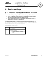
4 Device settings
4.1
Danfoss frequency converter VLT6000
The settings and the behaviour of the VLT6000 are influenced via parameters, which are
entered via the VLT's operating panel. Two levels have been provided for this.
•
•
In level 1 (standard), which is accessed by pressing the 'Quick Menu' button,
only the most commonly-used values can be influenced.
Level 2 (advanced) is accessed by pressing the 'Extended Menu' button; all
parameters can be altered or retrieved here.
For communication with the VLT6000, it is possible to communicate using either the
Danfoss FC protocol or an additional LonWorks card via the LON protocol.
The setting as to which of the two protocols is active is made via parameter 928 in the
Extended Menu. The two settings are described below:Parameter 928 – process control –
In force
Blocked
7001044003 R1
Additional LON card is active; FC protocol
is de-activated.
FC protocol is activated; additional LON
card is de-activated.
This setting should be chosen for the
system integration described
here.
Sauter Systems
11
nova230 for Danfoss
4
Device settings
In addition, communication is affected by the following parameters:Parameter
500
Type of protocol:
501
502
503
Meaning
0 = FC protocol
1 = Metasys N2
2 = Landis/Staefa FLN
Address (bus address from VLT) 0...126 valid
Baud rate (300, 600, 1200, 2400, 4800, 9600)
Freewheel lock:
0 = Digital input
1 = Serial communication
2 = Bus and terminal
3 = Bus or terminal
Choose setting
0 = FC protocol
0...126
9600
Consult
Danfoss before
setting.
504
DC brake:
0 = Digital input
1 = Serial communication
2 = Bus and terminal
3 = Bus or terminal
Consult
Danfoss before
setting.
505
Start:
0 = Digital input
1 = Serial communication
2 = Bus and terminal
3 = Bus or terminal
Consult
Danfoss before
setting.
506
Reverse:
0 = Digital input
1 = Serial communication
2 = Bus and terminal
3 = Bus or terminal
Consult
Danfoss before
setting.
507
Parameter-set selector:
0 = Digital input
1 = Serial communication
2 = Bus and terminal
3 = Bus or terminal
Consult
Danfoss before
setting.
A detailed description of each of the parameters can be found in the VLT6000's
engineering manual.
12
7001044003 R1
Sauter Systems
nova230 for Danfoss
4
Device settings
4.2
Connecting and setting the RS232/485
converter
The description refers to the RS232/485 converter of the type #86201 supplied by the
company W&T. This converter is electrically isolated, which prevents unwanted earth
circuits and problems connected therewith.
The circuitry should be created as described in Item 1.3. The DIP switches inside the
unit should be set as follows:S1-1: ON
S1-5: OFF
S1-2: ON
S1-6: ON
S1-3: OFF
S1-7: ON
S1-4: ON
S1-8: OFF
N.B.: S1-6 and S1-7 represent the bus terminating resistor
S1-1...5 define the operating mode
S1-8 is always OFF
In 'send' and 'receive' modes, the red LED on the converter should flicker.
The converter should be connected to the power supply unit that is included in delivery.
7001044003 R1
Sauter Systems
13
nova230 for Danfoss
4
14
Device settings
7001044003 R1
Sauter Systems
nova230 for Danfoss
5
The VLT6000's data points
5 The VLT6000's data points
Sending from BMS Æ FC, the following data points are possible:Data point
Command: setpoint
Command: FC start/stop
Command: fault reset
7001044003 R1
Parameter number
Unit
1
2
3
%
FBD
module
AO
DO
DO
Card code
0x80 or 0xA0
0x20 or 0x30
0x20 or 0x30
Sauter Systems
15
nova230 for Danfoss
5
The VLT6000's data points
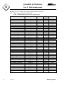
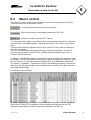
Reading from FC Æ BMS, the following data points are possible:N.B.: ZW = status word, AW = alarm word
EZW = extended status word, WW = warning word
16
Data point
Parameter number
Unit
Setpoint
Setpoint
Actual value
Frequency
Current
Consumption
Motor voltage
Intermediate-circuit voltage
Motor temperature
VLT temperature
Digital input KL33
Digital input KL32
Digital input KL29
Digital input KL27
Digital input KL19
Digital input KL18
Digital input KL17
Digital input KL16
Analogue input KL53
Analogue input KL54
Analogue input KL60
Pulse setpoint
External setpoint
ZW: Control ready
ZW: Drive ready
ZW: Stand-by
ZW: Cut-out
ZW: Warning
ZW: Speed OK
ZW: Remote control active
ZW: Frequency OK
ZW: Operation
ZW: Voltage fluctuation
ZW: Current limit
ZW: Thermal warning
Heat-sink temp.
AW: Unknown alarm
AW: Cut-out
AW: Auto-optimisation
error
503
510
511
512
514
515
517
518
519
520
521 Bit 0
521 Bit 1
521 Bit 2
521 Bit 3
521 Bit 4
521 Bit 5
521 Bit 6
521 Bit 7
522
523
524
525
526
527 Bit 0
527 Bit 1
527 Bit 2
527 Bit 3
527 Bit 7
527 Bit 8
527 Bit 9
527 Bit 10
527 Bit 11
527 Bit 13
527 Bit 14
527 Bit 15
528
529 Bit 0
529 Bit 1
529 Bit 2
%
%
%
Hz
A
KW
V
V
°C
°C
7001044003 R1
V
V
mA
Hz
%
°C
FBD
module
AI
AI
AI
AI
AI
AI
AI
AI
AI
AI
BI(fC8)
BI(fC8)
BI(fC8)
BI(fC8)
BI(fC8)
BI(fC8)
BI(fC8)
BI(fC8)
AI
AI
AI
AI
AI
BI(fC8)
BI(fC8)
BI(fC8)
BI(fC8)
BI(fC8)
BI(fC8)
BI(fC8)
BI(fC8)
BI(fC8)
BI(fC8)
BI(fC8)
BI(fC8)
AI
BI(fC8)
BI(fC8)
BI(fC8)
Card code
0x70
0x70
0x70
0x70
0x70
0x70
0x70
0x70
0x70
0x70
0x10
0x10
0x10
0x10
0x10
0x10
0x10
0x10
0x10
0x10
0x10
0x10
0x10
0x10
0x10
0x10
0x10
0x10
0x10
0x10
0x10
0x10
0x10
0x10
0x10
0x70
0x10
0x10
0x10
Sauter Systems
nova230 for Danfoss
5
The VLT6000's data points
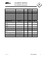
Data point
AW: Short circuit
AW: Switching-mode fault
AW: Earthing fault
AW: Excess current
AW: Current limit
AW: Motor thermistor
AW: Motor overload
AW: Inverter overload
AW: Under-voltage
AW: Excess voltage
AW: Mains-phase fault
AW: Setpoint error
AW: Heat-sink temp.
AW: Motor phase W is
missing
AW: Motor phase V is
missing
AW: Motor phase U is
missing
AW: Drive fault
AW: Output current low
AW: Safety stop
EZW (extended status
word)
WW (warning word)
Hours run, VLT
Motor running time
KWH counter
7001044003 R1
Parameter number
Unit
Card code
529 Bit 5
529 Bit 6
529 Bit 7
529 Bit 8
529 Bit 9
529 Bit 10
529 Bit 11
529 Bit 12
529 Bit 13
529 Bit 14
529 Bit 15
529 Bit 16
529 Bit 17
529 Bit 18
FBD
module
BI(fC8)
BI(fC8)
BI(fC8)
BI(fC8)
BI(fC8)
BI(fC8)
BI(fC8)
BI(fC8)
BI(fC8)
BI(fC8)
BI(fC8)
BI(fC8)
BI(fC8)
BI(fC8)
529 Bit 19
BI(fC8)
0x10
529 Bit 20
BI(fC8)
0x10
529 Bit 22
529 Bit 23
529 Bit 24
532 (see VLT
manual, page 151)
531 (see VLT
manual, page 151)
600
601
602
BI(fC8)
BI(fC8)
BI(fC8)
BI(fC8)
0x10
0x10
0x10
0x10
BI(fC8)
0x10
CI
CI
CI
0xD0
0xD0
0xD0
hrs
hrs
KWh
0x10
0x10
0x10
0x10
0x10
0x10
0x10
0x10
0x10
0x10
0x10
0x10
0x10
0x10
Sauter Systems
17
nova230 for Danfoss
5
18
The VLT6000's data points
7001044003 R1
Sauter Systems
nova230 for Danfoss
6
Generation of data for the AS
6 Generation of data for the AS
Data points are generated using an Excel application, which can run with either Excel 97
or Excel 2000. This allows up to 191 data points to be freely parameterised. Each of the
data points is chosen via drop-down lists within the table. Therefore, incorrect entries
are practically impossible.
The first MFA to be generated is MFA254. All other MFAs follow in descending order
until (at the most) MFA64 (smallest soft address).
Generation should take place from MFA254 onwards, leaving no gaps.
MFA255 cannot be used, since it is reserved for the communication fault message.
6.1
Tables
The application is split into four tables:1.
2.
3.
4.
Parameters
Data
MDBKONV
Language text (write-protected)
The following entries should be made for the whole installation (parameters table):1.
2.
3.
4.
5.
6.
7.
Date of creation
Name of installation
Protocol (fixed, no change required)
Baud rate: 9600 default
novaPro AS number 0...30
EYL 230 group address
Transmission channel, EYS290 card or (with a router) EYZ291, 21, 22 etc.
The following entries should be made for each data point (data table):1. Bus address of the VLT6000 0...126
2. Choice of type of data point from the combobox
3. MFA is fixed in the list and cannot be changed
It is also possible to duplicate already-generated data lines using Excel functions such
as Select, Copy, Paste, Auto-complete etc.
This may help to save time, particularly in the case of large installations requiring a lot of
generation work.
7001044003 R1
Sauter Systems
19
nova230 for Danfoss
6
Generation of data for the AS
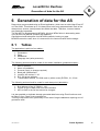
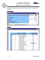
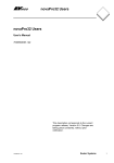
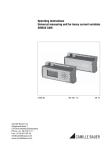
Excerpts from a generation table such as the one described above (Excel tables) are
shown below.
'Parameters' table
'Data' table
20
7001044003 R1
Sauter Systems
nova230 for Danfoss
6
Generation of data for the AS
6.2
Macro control
The various functions (macros) are controlled by buttons in the symbol bar (Danfoss).
These buttons have the following functions:Convert the data-point table into an Intel hex file.
Call up the window for downloading data into the EYL 230.
Create the novaPro text table (PZT import).
The 'Generate' button starts an automatic check of the generation operation. If there are
any faulty lines, a message appears, indicating the faulty line (the cursor is in the faulty
field).
This procedure should be repeated until all lines are free of errors (when a message to
this effect will appear).
Then, an Intel hex file with the data points will be created automatically. This hex file
presents the generation for the EYL 230, and should then be loaded into the AS by
using the 'Download' button.
In addition, an 'MDBKONV' table is created; this contains a ready-made generation table
for novaPro. This can be imported into another full generation table for novaPro by using
the 'PZT import' (i.e. import the data-point table) button of the MDBKONV4 application.
The 'Station', 'Installation', 'Transmission channel' and 'Building automation' columns are
taken from the 'Parameters' table; the remaining lines are read from the 'Data' table and
are prepared accordingly.
An example is shown below:-
This table now serves as the basis for a full MDBKONV generation. The tab-separated
export file (PZT3600.TXT) created from this is subsequently imported into the PZT
(data-point table) editor of novaPro and is then available in the PZT list.
7001044003 R1
Sauter Systems
21
nova230 for Danfoss
6
22
Generation of data for the AS
7001044003 R1
Sauter Systems
nova230 for Danfoss
7
Generation in the FBD editor
7 Generation in the FBD editor
7.1
Generating VLT6000 data points
Schematics are generated in the FBD editor with the following firmware modules:
BI:
AI:
DO:
AO:
messages, alarms from VLT
measured values from VLT
commands to VLT
setpoints to VLT
The firmware module to be chosen for the relevant DP type can be found in the table in
Ch. 1.5.
7.2
Generating collective alarms
On the EYL 230, the MFA255 is fixed with a special function and cannot be used for
anything else. If one of the VLTs fails, this address is set to 1.
Function of MFA
Collective alarm for
communication with the VLTs
7001044003 R1
Firmware module in the
FBD
AS card code
BI(fC8)
0x10
Sauter Systems
23
nova230 for Danfoss
7
24
Generation in the FBD editor
7001044003 R1
Sauter Systems
nova230 for Danfoss
8
Putting the EYL 230 F130 into operation
8 Putting the EYL 230 F130 into
operation
Procedure:1. For the transfer of data from the PC to the EYL 230, a data cable of the type VK291
(connecting cable PC→EYZ291) is used.
2. One end of this cable should be connected to COM1/COM2 on the PC, the other
end to the RS232 plug on the EYL 230.
3. Switch off the EYL 230.
4. Put the test jumper on the EYL 230 to the 'TEST' position.
5. Switch on the EYL 230. The red and green LEDs light up.
6. Wait for 5 seconds (EYL 230 F130 self-test).
7. Press the 'Download' button in the symbol bar.
8. Each of these steps are again listed in the form that subsequently appears.
9. Choose the correct interface.
10. Press the 'Send' button. The hex lines are shown in the message line and
transferred to the station. The telegrams can be read as they run through the
message box.
11. If the transfer was successful, the EEPROM's internal programming will be
forwarded to the EYL 230. If this has been carried out without faults, a message to
this effect will appear. If faults occur, an error message appears.
12. If faults occur, the whole procedure should be repeated as from Item 3 above.
13. If the faults continue to occur, the cable link should be checked and another
download carried out until the data have been successfully transmitted.
14. Without a complete download, no data can be interrogated.
15. These data are then again loaded from the EEPROM and a generation list is issued
at the monitoring interface.
16. The green LED then flashes at intervals of one second. Parameterising is now
complete and the EYL 230 can be switched off.
17. In order to work normally, the EYL 230's test jumper must be set back to the 'RUN'
position and the station has to be re-started (i.e. switched OFF and then ON again).
18. During normal operation with the VLTs, the green LED flashes at intervals of one
second.
If the cycle LED is continuously on or continuously off, a fault has occurred.
This usually indicates that there is an internal fault on the EYL 230, which should not
normally occur.
7001044003 R1
Sauter Systems
25
nova230 for Danfoss
8
26
Putting the EYL 230 F130 into operation
7001044003 R1
Sauter Systems
nova230 for Danfoss
9
VLT commissioning software (PC)
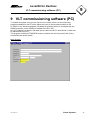
9 VLT commissioning software (PC)
To enable the system to be put into service more easily, there is a commissioning
program available for the PC which allows the user to check communication to the
VLT6000. It is a Windows program (Windows 9x and later) which is connected with the
RS485 converter via the COM port instead of the EYL 230.
Any VLT address can be set, and data can be read from the FC and viewed, or data can
be transferred to the VLT.
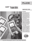
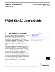
The program is called VLT6000.EXE and runs without the aid of any other files. Some
screenshots are shown below.
Main window:-
7001044003 R1
Sauter Systems
27
nova230 for Danfoss
9
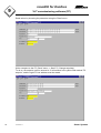
VLT commissioning software (PC)
Read values by choosing the parameter using the 'Read' menu.
Write a setpoint to the FC ('Send' menu → Start FC | Change setpoints).
To do so, the setpoint must be entered in % beforehand in the yellow field marked 'FC
setpoint', and the right FC bus address must be stated.
28
7001044003 R1
Sauter Systems
nova230 for Danfoss
10
Monitoring
10 Monitoring
On the EYL230F130, it is possible to introduce a monitoring circuit via terminal 126. To
do so, a two-core cable (RX and GND) should be connected at this terminal and at the
PC's COM port as follows:Pin assignment
AS side
(terminal)
126
⇒
⊥
⇔
PC side
(DB9 plug)
1
2 RXD
3 TXD
4
5 GND
6
7
8
9
Terminal settings:9600 baud
8 data bit
no parity
1 stop-bit
no handshake
Therefore, the complete data traffic from the station to the VLTs can be recorded and
logged at an ASCII terminal (Norton, Hyperterm etc.).
For this, the terminal program should be set to a baud rate of 9600, 8 data bit, no parity
and a stop-bit without handshake.
The test jumper should be put from the RUN position to the TEST position approx.
5 seconds after starting the station.
Three different responses are shown below:-
7001044003 R1
Sauter Systems
29
nova230 for Danfoss
10
Monitoring
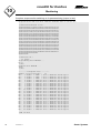
Complete sequence after switching on for parameterising (jumper in test).
Program-Start EYL 230 F130 Danfoss-VLT6000 Ind 'a'/29.01.02)
Download Datablock to AS...
100000005A0131322E31302E303000202000323370
100010003044414E46002020202020202020202057
1000200020202020202020202020202020006E6F53
1000300076614E65743C2D2D3E44616E666F737320
100040002D564C540020202020202020200000008D
1000500000000000000000000000000125800801F1
100060004500000A020064000A01F40200320000A8
100070000000000000000000000007D000050300A1
100080001601000100FE0101000200FD0101000354
1000900000FC010101FD00FB000101FE00FA00016E
1000A00001FF00F90001020000F80001020200F760
1000B0000001020300F60001020500F5000102063E
1000C00000F40001020700F30001020800F2000141
1000D000020900F10001020900F00001020901EF2C
1000E0000001020902F00001020903ED000102090A
1000F00004EC0001020905EB0001020906EA000117
05010000020907E900FF
00000001FF
Download O.K.!
18 Lines
Programming User-EEPROM ...
N.^^^
Done!
Reading User-EEPROM ...
^N^n^
Done!
-------- Datapoint-List -------Number of Data-Records =
22
Nr=
1 FCadr= 1 PNU= 1 Bit= 0
Nr=
2 FCadr= 1 PNU= 2 Bit= 0
Nr=
3 FCadr= 1 PNU= 3 Bit= 0
Nr=
4 FCadr= 1 PNU=509 Bit= 0
Nr=
5 FCadr= 1 PNU=510 Bit= 0
Nr=
6 FCadr= 1 PNU=511 Bit= 0
Nr=
7 FCadr= 1 PNU=512 Bit= 0
Nr=
8 FCadr= 1 PNU=514 Bit= 0
Nr=
9 FCadr= 1 PNU=515 Bit= 0
Nr= 10 FCadr= 1 PNU=517 Bit= 0
Nr= 11 FCadr= 1 PNU=518 Bit= 0
Nr= 12 FCadr= 1 PNU=519 Bit= 0
Nr= 13 FCadr= 1 PNU=520 Bit= 0
Nr= 14 FCadr= 1 PNU=521 Bit= 0
Nr= 15 FCadr= 1 PNU=521 Bit= 0
Nr= 16 FCadr= 1 PNU=521 Bit= 1
Nr= 17 FCadr= 1 PNU=521 Bit= 2
Nr= 18 FCadr= 1 PNU=521 Bit= 3
Nr= 19 FCadr= 1 PNU=521 Bit= 4
Nr= 20 FCadr= 1 PNU=521 Bit= 5
Nr= 21 FCadr= 1 PNU=521 Bit= 6
Nr= 22 FCadr= 1 PNU=521 Bit= 7
MFA=254
MFA=253
MFA=252
MFA=251
MFA=250
MFA=249
MFA=248
MFA=247
MFA=246
MFA=245
MFA=244
MFA=243
MFA=242
MFA=241
MFA=240
MFA=239
MFA=240
MFA=237
MFA=236
MFA=235
MFA=234
MFA=233
KC=A0
KC=30
KC=30
KC=70
KC=70
KC=70
KC=70
KC=70
KC=70
KC=70
KC=70
KC=70
KC=70
KC=10
KC=10
KC=10
KC=10
KC=10
KC=10
KC=10
KC=10
KC=10
Opt=1
Opt=1
Opt=1
Opt=0
Opt=0
Opt=0
Opt=0
Opt=0
Opt=0
Opt=0
Opt=0
Opt=0
Opt=0
Opt=0
Opt=0
Opt=0
Opt=0
Opt=0
Opt=0
Opt=0
Opt=0
Opt=0
End of List
30
7001044003 R1
Sauter Systems
nova230 for Danfoss
10
Monitoring
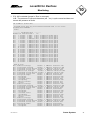
1. EYL 230 re-started (jumper in 'Run' or removed).
N.B.: The presence of unusual characters (aà etc.) is quite normal and does not
denote the presence of faults.
aà Coldboot (Power-Off)
Program-Start EYL 230 F130 Danfoss-VLT6000 Ind 'a'/29.01.02)
Reading User-EEPROM ...
.....
Done!
-------- Datapoint-List -------Number of Data-Records =
22
Nr=
1 FCadr= 1 PNU= 1 Bit= 0
Nr=
2 FCadr= 1 PNU= 2 Bit= 0
Nr=
3 FCadr= 1 PNU= 3 Bit= 0
Nr=
4 FCadr= 1 PNU=509 Bit= 0
Nr=
5 FCadr= 1 PNU=510 Bit= 0
Nr=
6 FCadr= 1 PNU=511 Bit= 0
Nr=
7 FCadr= 1 PNU=512 Bit= 0
Nr=
8 FCadr= 1 PNU=514 Bit= 0
Nr=
9 FCadr= 1 PNU=515 Bit= 0
Nr= 10 FCadr= 1 PNU=517 Bit= 0
Nr= 11 FCadr= 1 PNU=518 Bit= 0
Nr= 12 FCadr= 1 PNU=519 Bit= 0
Nr= 13 FCadr= 1 PNU=520 Bit= 0
Nr= 14 FCadr= 1 PNU=521 Bit= 0
Nr= 15 FCadr= 1 PNU=521 Bit= 0
Nr= 16 FCadr= 1 PNU=521 Bit= 1
Nr= 17 FCadr= 1 PNU=521 Bit= 2
Nr= 18 FCadr= 1 PNU=521 Bit= 3
Nr= 19 FCadr= 1 PNU=521 Bit= 4
Nr= 20 FCadr= 1 PNU=521 Bit= 5
Nr= 21 FCadr= 1 PNU=521 Bit= 6
Nr= 22 FCadr= 1 PNU=521 Bit= 7
MFA=254
MFA=253
MFA=252
MFA=251
MFA=250
MFA=249
MFA=248
MFA=247
MFA=246
MFA=245
MFA=244
MFA=243
MFA=242
MFA=241
MFA=240
MFA=239
MFA=240
MFA=237
MFA=236
MFA=235
MFA=234
MFA=233
End of List
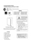
Nr= 10 Motor-Voltage
FCadr=
Nr= 11 Internal-Voltage
FCadr=
Nr= 12 Thermal.Stress Motor% FCadr=
Nr= 13 Thermal Stress VLT
FCadr=
Nr= 10 Motor-Vol Voltage
FCadr=
Nr= 12 Thermal.Stress Motor% FCadr=
Nr= 13 Thermal Stress VLT
FCadr=
Nr= 14 Digital-Input
FCadr=
Nr= 4 Setpoint
FCadr=
Nr= 5 Setpoint
FCadr=
Nr= 6 Current Value
FCadr=
Nr= 7 Frequency
FCadr=
Nr= 8 Motor-Current
FCadr=
Nr= 9 Power
FCadr=
Nr= 10 Motor-Voltage
FCadr=
Nr= 11 Internal-Voltage
FCadr=
Nr= 12 Thermal.Stress Motor% FCadr=
Nr= 13 Thermal Stress VLT
FCadr=
Nr= 14 Digital-Input
FCadr=
Nr= 4 Setpoint
FCadr=
Nr= 5 Setpoint
FCadr=
Nr= 6 Current Value
FCadr=
Nr= 7 Frequency
FCadr=
Nr= 8 Motor-Current
FCadr=
Nr= 9 Power
FCadr=
Nr= 10 Motor-Voltage
FCadr=
Nr= 11 Internal-Voltage
FCadr=
Nr= 12 Thermal.Stress Motor% FCadr=
Nr= 13 Thermal Stress VLT
FCadr=
Nr= 14 Digital-Input
FCadr=
Nr= 4 Setpoint
FCadr=
Nr= 5 Setpoint
FCadr=
7001044003 R1
KC=A0
KC=30
KC=30
KC=70
KC=70
KC=70
KC=70
KC=70
KC=70
KC=70
KC=70
KC=70
KC=70
KC=10
KC=10
KC=10
KC=10
KC=10
KC=10
KC=10
KC=10
KC=10
Opt=1
Opt=1
Opt=1
Opt=0
Opt=0
Opt=0
Opt=0
Opt=0
Opt=0
Opt=0
Opt=0
Opt=0
Opt=0
Opt=0
Opt=0
Opt=0
Opt=0
Opt=0
Opt=0
Opt=0
Opt=0
Opt=0
1 PNU=517 Value=21.700
1 PNU=518 Value=316.000
1 PNU=519 Value=0.000
1 PNU=520 Value=0.000
1 PNU=518 Value=316.000
1 PNU=519 Value=0.000
1 PNU=520 Value=0.000
1 PNU=521 Value=0008
1 PNU=509 Value=60.000
1 PNU=510 Value=29.999
1 PNU=511 Value=0.000
1 PNU=512 Value=30.000
1 PNU=514 Value=0.030
1 PNU=515 Value=0.000
1 PNU=517 Value=21.700
1 PNU=518 Value=316.000
1 PNU=519 Value=0.000
1 PNU=520 Value=0.000
1 PNU=521 Value=0008
1 PNU=509 Value=60.000
1 PNU=510 Value=29.999
1 PNU=511 Value=0.000
1 PNU=512 Value=30.000
1 PNU=514 Value=0.030
1 PNU=515 Value=0.000
1 PNU=517 Value=21.700
1 PNU=518 Value=316.000
1 PNU=519 Value=0.000
1 PNU=520 Value=0.000
1 PNU=521 Value=0008
1 PNU=509 Value=60.000
1 PNU=510 Value=29.999
Sauter Systems
31
nova230 for Danfoss
10
Monitoring
2. Telegram fault (either after the power supply has been removed from the
RS232/RS485 converter or when the VLT has stopped responding).
Nr= 9
Nr= 10
Nr= 11
Nr= 12
Error:
Error:
Error:
Error:
Error:
Error:
Error:
Error:
Error:
Error:
Power
FCadr= 1 PNU=515 Value=0.000
Motor-Voltage
FCadr= 1 PNU=517 Value=21.700
Internal-Voltage
FCadr= 1 PNU=518 Value=317.000
Thermal.Stress Motor% FCadr= 1 PNU=519 Value=0.000
FCadr= 1 PNU=520 Code=0007 : Tg-Length-Error!
FCadr= 1 PNU=520 Code=0000 : No Response from FC!
FCadr= 1 PNU=520 Code=0000 : No Response from FC!
FCadr= 1 PNU=521 Code=0000 : No Response from FC!
FCadr= 1 PNU=521 Code=0000 : No Response from FC!
FCadr= 1 PNU=521 Code=0000 : No Response from FC!
FCadr= 1 PNU=509 Code=0000 : No Response from FC!
FCadr= 1 PNU=509 Code=0000 : No Response from FC!
FCadr= 1 PNU=509 Code=0000 : No Response from FC!
FCadr= 1 PNU=510 Code=0000 : No Response from FC!
The cause of the fault is shown at the end of the line in plain text and in hexadecimal
format as a fault code.
Note
The test jumper can also be removed and inserted during operation (activate and deactivate the monitoring circuit).
Important
When monitoring has finished, the test jumper should be reset to RUN, otherwise the AS
will change to download mode after a reset (watchdog, malfunction etc.) and will then
cease to communicate.
32
7001044003 R1
Sauter Systems
nova230 for Danfoss
11
Language settings
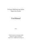
11 Language settings
For use with other languages, the Excel application can be set accordingly using the
language-text table provided. To do so, the table's protection has to be removed (no
password).
The German text in column A can then be translated line by line into another language
(e.g. English) in column B.
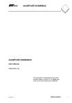
To choose a language, the number at the end of the 'Title' document property should be
set to the appropriate column number (A = 1 , B = 2 etc.). This property can be found
under 'File' menu → Properties → 'File info' tab.
The language-text table should then be protected again (without password) in order to
prevent any accidental changes.
The window in question is shown below (for default = German = 1).
7001044003 R1
Sauter Systems
33
nova230 for Danfoss
11
34
Language settings
7001044003 R1
Sauter Systems