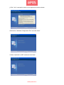
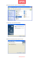
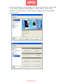
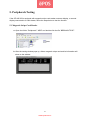
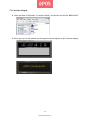
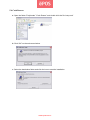
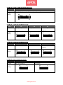
1
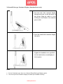
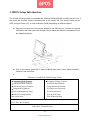
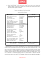
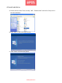
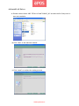
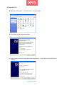
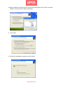
ATLAS 350
ALL-IN-ONE ( MONOBLOCK )
USER MANUAL
www.eposcom.ru
General Information
ABOUT THIS MANUAL
The purpose of this user’s manual is to provide general information on ePOS ATLAS-350 Series
POS terminal and to show the users how to configure the hardware-related configurations. The
information in this manual is subject to change without notice due to rapid improvement on IT
technology. The users can get the most up to date information from our web site
www.eposcom.ru
DISCLAIMER
This manual has been examined for accuracy. While precaution has been taken in the
preparation of this manual, neither the manufacturer takes no liability for errors or omissions nor
assume any responsibility for damage(s) incurred directly or indirectly from errors, omissions, or
discrepancies of this manual. IN NO EVENT WILL THE VENDOR BE LIABLE FOR DIRECT,
INDIRECT, SPECIAL, INCIDENTAL, OR CONSEQUENTIAL DAMAGES ARISING OUT OF THE
USE OR INABILITY TO USE THIS PRODUCT OR DOCUMENTATION, EVEN IF THE
POSSIBILITY OF SUCH DAMAGES HAS BEEN ADVISED. IN PARTICULAR, THE VENDOR
SHALL NOT HAVE LIABILITY FOR ANY HARDWARE, SOFTWARE, OR DATA STORED OR
USED WITH THE PRODUCT, INCLUDING THE COSTS OF REPAIRING, REPLACING, OR
RECOVERING SUCH HARDWARE, SOFTWARE OR DATA.
WARNING
The terminal has been tested and found to comply with the limits for a Class A digital device,
pursuant to Part 15 of the FCC rules. These limits are designed to provide reasonable protection
against harmful interface in a residential installation. This equipment can generate and radiate
radio frequency energy and, if not installed and used according to the instructions, may cause
harmful interference to radio communications. However, there is no guarantee that interface will
not occur under particular installation. If this equipment does cause harmful interference to radio
or television reception, which is found by turning the equipment off and on, the user is
encouraged to try to correct the interface by one or more of the following measures:
Reorient or relocate the receiving antenna
Increase the distance between the equipment or device
Connect the equipment to an outlet other than the receiver’s
Consult a dealer or an experienced radio/TV technician for assistance
i
www.eposcom.ru
CAUTION
The system is provided with a battery-powered Real-Time Clock circuit. There is a danger of
exposing and personal injury if the battery is incorrectly replaced or mistreated. Do not attempt to
disassemble the battery, immerse it in the water or expose it to fire.
WARRANTY LIMITS
If the ATLAS-350 series machine is disassem bled by any person other than the authorized
technicians, the warranty will be terminated. The users should consult his/her dealer for any
technical problems. Warranty does not cover any damage caused by improper use.
ii
www.eposcom.ru
IMPORTANT SAFETY INFORMATION
z
Read following instructions carefully.
z
Use only parts, especially power adapter, recommended by the manufacturer; unapproved
parts may be hazardous.
z
Before plugging the power cord into the AC inlet of the power supply unit, make sure the
voltage (either 110V or 220V) is properly applied to the power switch. Improper voltage will
cause damage to the power supply unit.
z
Power off the system and remove the power adapter while cleaning the system.
z
Before powering on the system, make sure all the peripherals are firmly installed.
z
Do not use the system near water, such as a bathtub, a washbowl, a kitchen sink, a laundry
tub, and a swimming pool. Do not expose the machine under direct sunlight, and keep it
away from any heat source.
z
Do not place the system on an unstable cart, stand or table. If the machine falls, it may injure
a person or cause serious damage to the appliance.
z
The system is equipped with a three-wire grounded plug with a third (grounding) pin. This is a
safety feature. If your outlet does not accommodate the three-wire plug, have an electrician
install a correct outlet, or use an adapter to ground the appliance safely. Do not leave out the
safety purpose of the grounded plug.
z
Do not allow anything to rest on the power cord. Do not locate the system where people may
walk on the cord.
z
Do not make the power outlet and extension cords overload. Overload can result in fire or
electric shock.
z
Do not push any object into the computer cabinet. Dangerous voltage points may be touched
and the parts may be shorted out resulting in fire or electric shock.
z
Do not attempt to service the system on your own. Opening or removing cover can expose
you to dangerous voltage or other hazards.
z
Power off the system before installing or removing non-PNP (plug and play) devices.
z
If any of the following situations occurs, unplug the systems from the power outlet
immediately and consult with a qualified service person:
1. The power cord or plug is damaged or frayed.
2. Liquid is spilled into the system.
3. The system is dropped or the cabinet is damaged.
z
When the system is not in use, cover the system and store it with care.
iii
www.eposcom.ru
Contents
ABOUT THIS MANUAL ....................................................................................................... i
DISCLAIMER......................................................................................................................... i
WARNING .............................................................................................................................. i
CAUTION .............................................................................................................................. ii
WARRANTY LIMITS ........................................................................................................... ii
TRADE MARKS AND SERVICE MARKS ......................................................................... ii
IMPORTANT SAFETY INFORMATION ............................................................................ iii
1. Introduction ......................................................................................................... 2
1.1 Unpacking......................................................................................................................... 2
1.2 System Overview.............................................................................................................. 4
1.3 I/O Ports............................................................................................................................ 7
1.4 Specifications.................................................................................................................... 9
2. Components & Peripherals Installation ......................................................... 11
2.1 Replace Hard Disk...........................................................................................................11
2.2 Install Rear Top Mount Customer Display (Cutebase only) .......................................... 13
2.3 Install Second Display (Standard-base only).................................................................. 14
2.4 Install Pole-type Customer Display (Standard-base only) ............................................. 15
3. BIOS Setup Information................................................................................... 16
Entering Setup ...................................................................................................................... 18
Main Menu ........................................................................................................................... 19
Standard CMOS Setup Menu ............................................................................................... 21
Advanced BIOS Features ..................................................................................................... 23
Advanced Chipset Features .................................................................................................. 26
Integrated Peripherals ........................................................................................................... 29
Power Management Setup .................................................................................................... 36
PnP/PCI Configurations ....................................................................................................... 38
PC Health Status................................................................................................................... 39
Frequency/Voltage Control................................................................................................... 41
4. Drivers Installation ........................................................................................... 42
4.1 Install Chipset driver ...................................................................................................... 42
4.2 Install Graphic ................................................................................................................ 45
4.3 Install Audio Driver ........................................................................................................ 49
4.4 Install LAN Driver.......................................................................................................... 50
4.5 Install Wi-Fi.................................................................................................................... 52
5. Peripherals Testing............................................................................................ 61
5.1 Magnetic Stripe Card Reader ......................................................................................... 61
5.2 Customer Display ........................................................................................................... 62
www.eposcom.ru
5.3 Second Display ............................................................................................................... 63
5.4 Cash Drawer ................................................................................................................... 65
6. Jumper Settings & Connectors ........................................................................ 68
6.1 The Main Board Jumper Location.................................................................................. 68
6.2 Jumper Settings .............................................................................................................. 69
6.3 Connectors ...................................................................................................................... 72
6.4 Internal pin define........................................................................................................... 73
www.eposcom.ru
1. Introduction
1.1 Unpacking
The contents may vary with different options. If there’s any physical damage or missing parts,
please contact your supplier immediately. Please keep all packing materials in case you need to
ship back the device for service.
Unpacking ATLAS-350
The ATLAS-350 and accessories are packed in a paperboard carton. And it is wrapped by foam
padding for protection during shipping.
2
www.eposcom.ru
ATLAS-350
ATLAS-350
ATLAS-350 main system
HDD ( 2.5” SATA )
/ Compa ct F lash (Option) / Dis k on Module (Option)
SODIMM DDR2 (1 ~ 4GB)
CPU : Intel Core Duo T2500 2GHz or Core 2 Duo T7400 2.16GHz
Power adapter (Hidden on Base)
AC power cord
Driver CD
Magnetic stripe card reader (Option)
Customer display (Option)
WiFi module (Option)
3
www.eposcom.ru
1.2 System Overview
Front View
Rear View
www.eposcom.ru
z
Bottom View
z
Side View
www.eposcom.ru
Options:
Cutebase
Standard
www.eposcom.ru
1.3 I/O Ports
Port
Description
USB
Connect devices with USB connectors. There are 4 external USB ports
reserved and two additional left side ports.
Mouse
PS/2 Mouse Connector
KB
PS/2 Keyboard Connector
PWR IN
A 4 din rounded-power-jack for connecting an AC to DC +12V power
adapter.
PWR COM
COM 1/2 support power RI/5/12V ,refer to the PWR COM Jumper
Setting figure in page 8.
Extend KB
8-pin pitch 2.0 for keyboard.
AUDIO OUT
Earphone or speaker connector with 2 internal speakers.
DC12V OUT
12VDC jack for customer display (VFD).
Serial
3 x COM with Power Selected 5/12V on pin9 1 x COM for Touch
Option, 1 x COM Reserved 4 x DB9 RS-232. COM 1/2/4: pin 9
RI/5V/12V selected by jumper.
CASH DRAWER
RJ11 connector with selected 12/24V
LAN
RJ-45 connector with link/ack integrates speed LED and supports
wake-from-LAN function.
CF
A slot for inserting CF card
VGA
A 15 pin D-type connector serves to transmit VGA data to the monitor.
www.eposcom.ru
PWR COM Jumper Setting
COM
1
2
Voltage
Voltage
RI(Defult)
5V
12V
www.eposcom.ru
Cash
Drawer
pin5-6
Pin11-12
pin3-4
pin9-10
pin1-2
pin7-8
12V
Pin13-14
24V
Pin15-16
1.4 Specifications
ATLAS-350
Model
Main Board
CPU Support
Intel Celeron M 440 (1.86GHz , 1M Cache, 533M FSB)
Intel Core Duo T2500 (2GHz , 2M Cache , 667M FSB)
Intel Core 2 Duo T7400 (2.16GHz , 4M Cache, 667M FSB)
Chipset
Intel 82945GME + 82801GBM(ICH7)
System Memory
2 x 200pin DDR2 533/667MHz SODIMM Socket , up to 4GB
Graphic Memory
Share System Memory 64~224MB
BIOS
Award
LCD Touch Panel
LCD Size
12.1”
15”
17”
Brightness
400nits
250nits
300nits
Resolution
1024 x 768
1024 x 768
1280 x 1024
Touch Screen
5 wire Resistive or SAW
Tile Angle
15~80 Degree
Storage
HDD
1 x 2.5” SATA HDD Bay
Flash Memory
1 x Compact Flash Slot (Type 1 & 2)
Internal Expansion
USB 2.0
1 x Touch , 1 x WI-FI
Serial
1 x COM for Touch Option, 1 x COM Reserved
I/O Ports
USB 2.0
4 x External I/O, 2 x Left Side I/O
Serial
3 x COM with Power Selected 5/12V on pin9
Parallel
1 x DB25
PS2
1 x KB , 1 x MS on Left Side I/O
LAN
2 x Giga LAN ( Realtek 8111C)
2nd Display
1 x VGA, DB15
Cash Drawer
1 x RJ11, Selected 12/24V
DC In
1 x 4pin 12V , 7.5A
DC Out
1 x 12V for Customer or 2nd Display
Audio
1 x Line Out, 1 x Mic In, 2 x Internal Speaker 2W
Power
Power Adapter
Hidden on Base, 12V , 90W ,w/ Cable Head Lock
Indicator
1 x Power LED in Blue
Optional Peripheral
9
www.eposcom.ru
MSR
3 Track, PS2 or USB or COM
Customer Display
VFD / LCD, Rear Mount or Pole Type
2nd Display
12.1”, 15” with or without Touch
Environment
EMC & Safety
FCC & CE
Operating Temp.
0 ~ 40℃
Storage Temp.
-20 ~ 55℃
Operating Humidity
20% ~ 80% RH non-condensing
Storage Humidity
20% ~ 85% RH non-condensing
Dimension(WxDxH)
310x260x290mm
369x260x340mm
396x260x377mm
Weight (Kgs)
5.7
6.3
7.3
OS Support
POS Ready, XP Pro, Vista, Linux
10
www.eposcom.ru
2. Components & Peripherals Installation
2.1 Replace Hard Disk
a. Lift the cover from the upper side edges
as marked by the circles and push it down
to remove it.
b. Lossen the screw x 4 on the VESA
bracket.
c. Turn over the system to loosen the screw
x 2 on the back of the panel.
www.eposcom.ru
d. Remove the panel from the VESA bracket.
e. Loosen the screw on the cover of the hard
disk bay to remove the cover.
f.
Loosen the spacer.
www.eposcom.ru
g. Hold the hard disk and take it out in the
direction.
Then unplug it from the connector.
h. Loosen the 4 screws to remove the hard
disk from the bracket. Then install the
new hard disk following the above steps
with the order reversed.
2.2 Install Rear Top Mount Customer Display (Cutebase only)
a. Pass cord of the rear top mount display
through the holes in the direction af arrows
carefully. Plug the cable to a free COM port
and connect the extension power cable.
www.eposcom.ru
b. Press the stand of the customer display
into place.
2.3 Install Second Display (Standard-base only)
Hold the second display and turn the system
over carefully. Pass the cord through the
holes in the directions of the arrows. Plug the
cable into the VGA port and connect the
extension power cable.
Tighten the bundled screws specified for
the stand of the second display to fix it to
place.
www.eposcom.ru
2.4 Install Pole-type Customer Display (Standard-base only)
a. Pass the cord of the customer display
through the holes in the directions of
the arrows. Plug the cable to a free
COM port and connect the extension
power cable.
b. Press the stand of the customer display
into place.
c. Tighten the bundled screws specified
for the stand of the second display to
fix it to place.
Note
z
For the Cutebase type, there is no Second Disply/Pole-type Display option.
z
The rear top mount customer display has been pre-installed in factory.
www.eposcom.ru
3. BIOS Setup Information
The ATLAS-350 main board is compatible with Windows 95/98/2000/XP and Red Hat Linux 9.0. If
the drivers are required, find the necessary files in the support CD. The storage media can be
HDD, Compact Flash (CF), or Disk on Module (DOM) depending on different options.
a. Plug the AC power cord of the power adapter to the PWR IN port. Connect an external
CD-ROM to the POS system as the figure shown below and insert the installation CD for
the Operating System.
b. Turn on the system, press DEL to enter the BIOS main menu, select “Advanced BIOS
Features” and click Enter.
c.
Phoenix- AwardBIOS CMOS Setup Utility
Standard CMOS Features
Advanced BIOS Features
Advanced Chipset Features
Integrated Peripherals
Power Management Setup
PnP/PCI Configurations
Frequency/Voltage Control
Load Fail-Safe Defaults
Load Optimized Defaults
Set Supervisor Password
Set User Password
Save & Exit Setup
Exit Without Saving
PC Health Status
ESC : Quit
F10 : Save & Exit Setup
↑ ↓ → ← : Select Item
Time, Date, Hard Disk Type …
16
www.eposcom.ru
d. Select “USB-CDROM” at Fitst Boot Device. Press F10 to save and exit setup, then
restart the system. It will enter the “Setup from CD-ROM” mode. Insert the setup CD to
start the Operation System installation.
Phoenix- AwardBIOS CMOS Setup Utility
Advanced BIOS Features
►CPU Feature
►Hard Disk Boot Priority
Virus Warning
CPU L1 & L2 Cache
CPU L3 Cache
Hyper-Threading Technology
Quick Power On Self Test
First Boot Device
Second Boot Device
Third Boot Device
Boot Other Device
Boot Up NumLock Status
Gate A20 Option
Typematic Rate Setting
x Typematic Rate (Chars/Sec)
x Typematic Delay (Msec)
Security Option
MPS Version Control For OS
OS Select For DRAM > 64M
Report No FDD For WIN 95
Small Logo(EPA) Show
↑↓→←: Move
Enter: Select
F5: Previous Values
[Press Enter]
[Press Enter]
[Disabled]
[Enabled]
[Enabled]
[Enabled]
[Enabled]
[USB-CDROM]
[Hard Disk]
[USB-FDD]
[Enabled]
[On]
[Fast]
[Disabled]
6
250
[Setup]
[1.4]
[Non-OS2]
[No]
[Disabled]
+/-/PU/PD: Value
F10: Save
F6: Fail-Safe Defaults
Item Help
Menu Level
ESC: Exit
f
F1: General Help
F7: Optimized Defaults
AEB-945GME0 is equipped with the AWARD BIOS stored in SPI Flash ROM. These BIOS has
a built-in Setup program that allows users to modify the basic system configuration easily.
This
type of information is stored in CMOS RAM so that it is retained during power-off periods. When
system is turned on, AEB-945GME0 communicates with peripheral devices and checks its
hardware resources against the configuration information stored in the CMOS memory. If any
error is detected, or the CMOS parameters need to be initially defined, the diagnostic program
will prompt the user to enter the SETUP program. Some errors are significant enough to
www.eposcom.ru
abort the start-up.
Entering Setup
Turn on or reboot the computer. When the message “Hit <DEL> if you want to run SETUP”
appears, press <Del> key immediately to enter BIOS setup program.
If the message disappears before you respond, but you still wish to enter Setup, please restart
the system to try
button.
“COLD START” again by turning it OFF and then ON, or touch the "RESET"
You may also restart from “WARM START” by pressing
keys simultaneously.
<Ctrl>, <Alt>, and <Delete>
If you do not press the keys at the right time and the system will not boot,
an error message will be displayed and you will again be asked to,
Press <F1> to Run SETUP or Resume
In HIFLEX BIOS setup, you can use the keyboard to choose among options or modify the
system parameters to match the options with your system.
keystroke functions in BIOS setup.
General Help
↑↓→
←
: Move
Enter
: Select
+ / - /PU /PD
: Value
ESC
: Exit
F1
: General Help
F2
: Item Help
F5
: Previous Values
F6
: Fail-Safe Defaults
F7
: Optimized Defaults
F9
: Menu in BIOS
F10
: Save
www.eposcom.ru
The table below will show you all of
Main Menu
If you enter AEB-945GME0 AWARD BIOS CMOS Setup Utility, you should start with the Main
Menu. The Main Menu allows you to select from fourteen setup functions and two exit choices.
Use arrow keys to switch among items and press <Enter> key to accept or bring up the
sub-menu.
Phoenix- AwardBIOS CMOS Setup Utility
f Standard CMOS Features
f Advanced BIOS Features
f Advanced Chipset Features
f Integrated Peripherals
f Power Management Setup
f PnP/PCI Configurations
fFrequency/Voltage Control
Load Fail-Safe Defaults
Load Optimized Defaults
Set Supervisor Password
Set User Password
Save & Exit Setup
Exit Without Saving
f PC Health Status
↑ ↓ → ← : Select Item
ESC : Quit
F10 : Save & Exit Setup
Time, Date, Hard Disk Type …
Note:
It is strongly recommended to reload Optimal Setting if CMOS is lost or BIOS is updated.
▲Standard CMOS Features
This setup includes SBC parameter as Time , Date , Hard Disk Type ……
▲Advanced BIOS Features
For choice special enhance feature .
▲Advanced Chipset Features
This setup include display and onboard device setup.
▲ Integrated Peripherals
This setup include on board peripheral setup.
www.eposcom.ru
▲Power Management Setup
This setup can be set SBC power management.
▲PnP/PCI Configurations
This setup can be set PCI configuration & resource.
▲PC Health Status
This setup can display SBC health state as voltage , board temperature … etc.
▲Frequency/Voltage Control
This setup can control CPU clock and frequency ratio.
▲Load Fail-Safe Defaults
This setup contain BIOS all item default setup in safe mode.
▲Load Optimized Default
This setup contain BIOS all item default setup in best performance mode.
▲Set Supervisor Password
Set password to allow access into the BIOS setup for supervisor.
▲Set User Password
This setup can set password to allow access into the BIOS limit setup.
▲Save & Exit Setup
Save BIOS setup value to CMOS and exit setup.
▲Exit Without Saving
Exit setup and keep last time setup value.
www.eposcom.ru
Standard CMOS Setup Menu
This setup page includes all the items in a standard compatible BIOS. Use the arrow keys to
highlight the item and then use the <PgUp>/<PgDn> or <+>/<-> keys to select the value or
number you want in each item and press <Enter> key to certify it.
Follow command keys in CMOS Setup table to change Date, Time, and IDE item.
Phoenix- AwardBIOS CMOS Setup Utility
Standard CMOS Features
Date (mm:dd:yy)
Time (hh:mm:ss)
Item Help
Thu, Jul 6 2007
21 : 29 : 50
Menu Level
f IDE Primary 0 Master
f IDE Primary 0 Slave
f IDE Secondary 1 Master
f IDE Secondary 1 Slave
[HDS728080PLAT20]
[None]
[None]
[None]
Video
Halt On
[EVG/VGA]
[All, But Keyboard]
Base Memory
Extended Memory
Total Memory
640K
1038336K
1038336K
↑↓→←: Move
Enter: Select
F5: Previous Values
+/-/PU/PD: Value
F10: Save
F6: Fail-Safe Defaults
▲Date
The data format : [week],[month],[day],[year].
▲Time
The time format : [hour],[minute],[second].
▲IDE Primary 0 Master
Auto detect IDE device on channel 0,
Press “Enter” for automatic device detection.
www.eposcom.ru
f
Change the day, month, year
and century
ESC: Exit
F1: General Help
F7: Optimized Defaults
▲IDE Primary 0 Slave
Auto detect IDE device on channel 0,
Press “Enter” for automatic device detection.
▲IDE Primary 1 Master
Auto detect IDE device on channel 1,
Press “Enter” for automatic device detection.
▲IDE Primary 1 Master
Auto detect IDE device on channel 1,
Press “Enter” for automatic device detection.
▲Video
Select the type of primary video subsystem in your computer. The BIOS usually
detects the correct video type automatically.
EGA/VGA
Enhance Graphics Adapter/Video Graphics Array.
For EGA, VGA, SEGA, SVGA or PGA monitor adapters.
CGA40
Color Graphics Adapter, power up in 40 column mode.
CGA80
Color Graphics Adapter, power up in 80 column mode.
MONO
Monochrome adapter, includes high resolution
monochrome adapters.
▲Halt On
During the power-on self-test(POST), the computer stops if the BIOS detects a
hardware error. You can tell the BIOS to ignore certain errors during POST and
continue the boot-up process. These are the selections:
No errors
All errors
All,
But keyboard
POST does not stop for any errors.
If the BIOS detects any non-fatal error, POST stops and prompts
you to take corrective action.
POST does not stop for a keyboard error, but stops for all other
errors.
▲Base Memory
Typically 640 KB. Also called conventional memory. The DOS operating system and
conventional applications use this area.
▲Extended Memory
Above the 1-MB boundary. Early IBM personal computers could not use memory above 1MB,
but current PCs and their software can use extended memory.
www.eposcom.ru
▲Total Memory
Total system memory available area.
Advanced BIOS Features
This section allows you to configure your system for basic operation.
You have the opportunity
to select the system’s default speed, boot-up sequence, keyboard operation, shadowing and
security.
Phoenix- AwardBIOS CMOS Setup Utility
Advanced BIOS Features
►CPU Feature
►Hard Disk Boot Priority
Virus Warning
CPU L1 & L2 Cache
CPU L3 Cache
Hyper-Threading Technology
Quick Power On Self Test
First Boot Device
Second Boot Device
Third Boot Device
Boot Other Device
Boot Up NumLock Status
Gate A20 Option
Typematic Rate Setting
x Typematic Rate (Chars/Sec)
x Typematic Delay (Msec)
Security Option
MPS Version Control For OS
OS Select For DRAM > 64M
Report No FDD For WIN 95
Small Logo(EPA) Show
↑↓→←: Move
Enter: Select
F5: Previous Values
[Press Enter]
[Press Enter]
[Disabled]
[Enabled]
[Enabled]
[Enabled]
[Enabled]
[USB-CDROM]
[Hard Disk]
[USB-FDD]
[Enabled]
[On]
[Fast]
[Disabled]
6
250
[Setup]
[1.4]
[Non-OS2]
[No]
[Disabled]
+/-/PU/PD: Value
F10: Save
F6: Fail-Safe Defaults
www.eposcom.ru
Item Help
Menu Level
ESC: Exit
f
F1: General Help
F7: Optimized Defaults
▲CPU Feature
Display CPU parameter information.
▲Hard Disk Boot Priority
Select boot sequence for HDD type device.
▲CPU L1 & L2 Cache
CPU L1 & L2 function Enabled/Disabled.
▲CPU L3 Cache
CPU L3 function Enabled/Disabled.
▲First Boot Device
Select boot device1.
Ex : HDD , CDROM ….
▲Second Boot Device2
Select boot device.
Ex : HDD , CDROM …
▲Third Boot Device
Select boot device3. Ex : HDD , CDROM …
Note : If boot device 1-3 setup as CD-ROM,HDD,USBFDD ,
System will follow setup to boot system.
▲Gate A20 Option
Fast-lets chipsets control Gate A20 and Normal – a pin in the keyboard controller controls
Gate A20. Default is Fast.
The choice: Normal, Fast.
▲Typematic Rate Setting
Keystrokes repeat at a rate determined by the keyboard controller – When enabled, the
typematic rate and typematic delay can be select.
The choice: Enabled, Disabled.
▲Typematic Rate (Chars/sec)
The rate at which character repeats when you hold down a key.
The choice: 6, 8, 10, 12, 15, 20, 24, and 30.
www.eposcom.ru
▲Typematic delay (Msec)
The delay before key strokes begin to repeat.
The choice: 250, 500, 750, and 1000.
▲Security Option
You can setup Setup/System when setup password.
Setup : In boot picture will show “Enter Password” message.
System : Into BIOS setup figure will show “Enter Password” message.
▲MPS Version Control For OS
The choice: 1.1, 1.4.
▲Report No FDD For WIN 95
The choice: No, Yes
▲OS Select For DRAM > 64M
Select OS/2 only if you are running OS/2 operating system with greater than 64MB of RAM on
the system.
The choice: Non-OS2, OS2.
▲Small Logo(EPA) Show
Enabled/Disabled Small Logo.
www.eposcom.ru
Advanced Chipset Features
This section allows you to configure the system based on the specific features of the Intel
945GME Chipset. This Chipset manages bus speeds and access to system memory
resources.VGA display port and onboard device control. It also coordinates communications
between the conventional ISA bus and the PCI bus.
never need to be altered.
It must be stated that these items should
The default settings have been chosen because they provide the
best operating conditions for your system.
The only time you might consider making any
changes would be if you discovered that data was being lost while using your system.
Phoenix- AwardBIOS CMOS Setup Utility
Advanced Chipset Features
Item Help
DRAM Timing Selectable
[By SPD]
x CAS Latency Time
Auto
x DRAM RAS# to CAS# Delay
Auto
x DRAM RAS# Precharge
Auto
x Precharge delay (tRAS)
Auto
x System Memory Frequency
Auto
SLP_S4# Assertion Width
[1 to 2 sec. ]
System BIOS Cacheable
[Enabled]
Video BIOS Cacheable
[Disabled]
Memory Hole At 15M-16M
[Disabled]
►PCI Express Root Port Function[Press Enter]
** VGA Setting **
PEG/Onchip VGA Control
On-Chip Frame Buffer Size
DVMT Mode
DVMT/FIXED Memory Size
Boot Display
Panel Type by Hardware
x Panel Number
Onboard LAN1
Onboard LAN2
↑↓→←: Move
Enter: Select
F5: Previous Values
[Auto]
[8MB]
[DVMT]
[128 MB]
[Auto]
[Enabled]
1024x768
[Enabled]
[Enabled]
+/-/PU/PD: Value
Menu Level
f
24Bit
F10: Save
F6: Fail-Safe Defaults
www.eposcom.ru
ESC: Exit
F1: General Help
F7: Optimized Defaults
▲CAS Latency Time
This option controls the number of SCLKs between the time a read command is sampled by
the SDRAMs and the time the GMCH samples correspondent data from the SDRAMs.
Default : Auto.
▲Active to Precharge Delay
This is to DDR standard accordingly
Default : Auto.
▲DRAM RAS# to CAS# Delay
This option controls the number of SCLKs (SDRAM Clock) from a row activate command to a
read or write command. If your system installs good quality of SDRAM, Normally, the option
will be set to Auto.
▲DRAM RAS# Precharge
This option controls the number of SCLKs for RAS# precharge. If your system installs good
quality of SDRAM,
It is set to auto normally.
▲System Memory Frequency
This option controls the number of System Memory Frequency.
It is set to auto normally.
▲SLP_S4# Assertion Width
This option controls SLP_S4# Assertion Width
Default : [1 to 2 sec. ]
▲System BIOS Cacheable
Selecting Enabled allows caching of the system BIOS ROM at F0000h-FFFFFh, resulting in
better system performance.
However, if any program writes to this memory area, a system
error may result.
▲System BIOS Cacheable
Select “Enabled” to enable caching VGA BIOS into L2 cache to get higher display
performance. “Disabled” to ignore this BIOS caching function.
▲Memory Hole At 15M-16M
This setting allows users to enable or disable the 1MB of memory required by
some ISA expansion cards.
www.eposcom.ru
▲PCI Express Root Port Function
This setting allows users to setup for some PCI Express chip function.
** VGA Setting **
▲PEG/Onchip VGA Control
Setup Onchip VGA Control. Default : Auto.
▲On-Chip Frame Buffer Size
Setup On-Chip Frame Buffer Size: 8MB.
▲DVMT Mode
DVMT Mode select : Enabled DVMT.
▲DVMT/FIXED Memory Size
Setup DVMT/FIXED Memory Siz: 128MB.
▲Boot Display
To setup boot display port as [Auto] , [CRT] , [LFP] ,[CRT+LFP].
▲Panel Type by Hardware
[Enabled]
Select Panel type by onboard jump : JLCD_SEL
Please refer hardware jump setting.
[Disabled]
Depend on BIOS setup for panel resolution.
▲Panel Number
These fields allow you to select the LCD Panel type. The default values for
these ports are :
800x600 18Bit
1024x768 18Bit
1024x768 24Bit
1280x1024 24Bit
▲On chip LAN1
Enabled or Disable LAN1 function.
www.eposcom.ru
▲On chip LAN2
Enabled or Disable LAN2 function.
Integrated Peripherals
Phoenix- AwardBIOS CMOS Setup Utility
Integrated Peripherals
f OnChip IDE Device
f Onboard Device
f Super IO Device
Onboard Lan Boot ROM
Watch Dog Timer Select
Onboard Serial Port 3
Serial Port 3 Use IRQ
Onboard Serial Port 4
Serial Port 4 Use IRQ
Onboard Serial Port 5
Serial Port 5 Use IRQ
Onboard Serial Port 6
Serial Port 6 Use IRQ
f USB Device Setting
↑↓→←: Move
Enter: Select
F5: Previous Values
[Press Enter]
[Press Enter]
[Press Enter]
[Disabled]
[Disabled]
[3E8]
[IRQ10]
[2E8]
[IRQ11]
[4F8]
[IRQ5]
[4E8]
[IRQ11]
[Press Enter]
+/-/PU/PD: Value
F10: Save
F6: Fail-Safe Defaults
▲OnChip IDE Device
Display IDE device mode setting.
▲Onboard Device
Display On board device content.
▲Super IO Device
Display Super IO device item.
▲Onboard Serial Port 3
Serial IO Port 3 address value [3E8].
www.eposcom.ru
Item Help
Menu Level
ESC: Exit
f
F1: General Help
F7: Optimized Defaults
▲Serial Port 3 Use IRQ
Serial IO Port 3 IRQ value [10].
▲Onboard Serial Port 4
Serial IO Port 4 address value [2E8].
▲Serial Port 4 Use IRQ
Serial IO Port 4 IRQ value [11].
▲Onboard Serial Port 5
Serial IO Port 5 address value [4F8].
▲Serial Port 5 Use IRQ
Serial IO Port 5 IRQ value [5].
▲Onboard Serial Port 6
Serial IO Port 6 address value [4E8].
▲Serial Port 6 Use IRQ
Serial IO Port 6 IRQ value [11].
▲USB Device Setting
Display USB device advance item.
www.eposcom.ru
Phoenix- AwardBIOS CMOS Setup Utility
OnChip IDE Device
IDE HDD Block Mode
IDE DMA transfer access
On-Chip Primary PCI IDE
IDE Primary Master PIO
IDE Primary Slave PIO
IDE Primary Master UDMA
IDE Primary Slave UDMA
On-Chip Secondary PCI IDE
IDE Secondary Master PIO
IDE Secondary Slave PIO
IDE Secondary Master UDMA
IDE Secondary Slave UDMA
Item Help
[Enabled]
[Enabled]
[Enabled]
[Auto]
[Auto]
[Auto]
[Auto]
[Enabled]
[Auto]
[Auto]
[Auto]
[Auto]
Menu Level
f
If your IDE hard drive
Supports block mode
Select Enabled for
Automatic detection of
The optimal number of
block read/writes per
sector the drive can
support
** On-Chip Serial ATA Setting **
On chip Serial ATA
[Auto]
X SATA PORT Speed Settings
Disabled
X PATA IDE Mode
Primary
SATA Port
P1,P3 is secondary
↑↓→←: Move
Enter: Select
+/-/PU/PD: Value
F5: Previous Values
F10: Save
F6: Fail-Safe Defaults
ESC: Exit
F1: General Help
F7: Optimized Defaults
▲IDE HDD Block Mode
Block mode is also called block transfer, multiple commands, or multiple sector read/write.
▲IDE DMA transfer access
UDMA (Ultra DMA) is a DMA data transfer protocol that utilizes ATA commands and the ATA
bus to allow DMA commands to transfer data at a maximum burst rate of 33 MB/s.
▲On-Chip Primary
PCI IDE
▲On-Chip Secondary PCI IDE
The chipset contains a PCI IDE interface with support for two IDE channels. Select Enabled to
activate the IDE interface. Select Disabled to deactivate this interface, if you install a primary
and/or secondary add-in IDE interface.
www.eposcom.ru
▲IDE Primary Master PIO
▲IDE Primary Slave PIO
▲Secondary Master PIO
▲Secondary Slave PIO
The four IDE PIO (Programmed Input/Output) fields let you set a PIOmode (0-4) for each of
the four IDE devices that the onboard IDE interface supports. Modes 0 through 4 provide
successively increased performance. In Auto mode, the system automatically determines the
best mode for each device.
▲IDE Primary Master UDMA
▲IDE Primary Slave UDMA
▲IDE Secondary Master UDMA
▲IDE Secondary Slave UDMA
UDMA (Ultra DMA) is a DMA data transfer protocol that utilizes ATA commands and the ATA
bus to allow DMA commands to transfer data at a maximum burst rate of 33 MB/s. When you
select Auto in the four IDE UDMA fields (for each of up to four IDE devices that the internal
PCI IDE interface supports), the system automatically determines the optimal data transfer
rate for each IDE device.
▲On-Chip Serial ATA Setting
The fields under the SATA setting include On-chip Serial ATA(Auto),
PATA IDE Mode(Primary) and SATA Port(P1,P3 is Secondary).
AHCI function is setup at Enhance mode.
www.eposcom.ru
Phoenix- AwardBIOS CMOS Setup Utility
Onboard Device
Azalia/AC97 Audio Select
↑↓→←: Move
Enter: Select
F5: Previous Values
[Auto]
+/-/PU/PD: Value
Menu Level
F10: Save
F6: Fail-Safe Defaults
ESC: Exit
f
F1: General Help
F7: Optimized Defaults
▲Azalia/AC97 Audio Select
Onboard Audio chip Auto/disabled select.
Phoenix- AwardBIOS CMOS Setup Utility
Super IO Device
Onboard Serial Port 1
Onboard Serial Port 2
UART Mode Select
X RxD, TxD Active
X IR Transmission Delay
X UR2 Duplex Mode
X Use IR Pins
Onboard Parallel Port
Parallel Port Mode
X EPP Mode Select
X ECP Mode Use DMA
PWRON After PWR-Fail
↑↓→←: Move
Enter: Select
F5: Previous Values
[3F8/IRQ4]
[2F8/IRQ3]
[Normal]
Hi, Lo
Enabled
Half
IR-Rx2Tx2
[378/IRQ7]
[SPP]
EPP1.7
3
[Off]
+/-/PU/PD: Value
Menu Level
F10: Save
F6: Fail-Safe Defaults
www.eposcom.ru
ESC: Exit
f
F1: General Help
F7: Optimized Defaults
▲Onboard Serial Port 1
Serial IO Port 1 address/IRQ value [3F8/IRQ4].
▲Onboard Serial Port 2
Serial IO Port 2 address/IRQ value [2F8/IRQ3].
▲Onboard Parallel Port
Parallel Port address/IRQ value [378/IRQ7].
▲UART Mode select
This field determines the UART mode in your computer. The default value is
Normal. Other options include ASKIR and IrDA.
▲Parallel Port Mode
Select an operating mode for the onboard parallel (printer) port. Select
Normal, Compatible, or SPP unless you are certain your hardware and
software both support one of the other available modes.
▲PWRON After PWR-Fail
This item allows user to configure the power status of using ATX power supply after a serious
power loss occurs.
On
System automatically restores power back
Off
System stays at power –off
www.eposcom.ru
Phoenix- AwardBIOS CMOS Setup Utility
USB Device Setting
USB 1.0 Controller
USB 2.0 Controller
USB Operation Mode
USB Keyboard Function
USB Mouse Function
USB Storage Function
[Enabled]
[Enabled]
[High Speed]
[Enabled]
[Enabled]
[Enabled]
Menu Level
[Enabled] or [Disabled]
Universal Host
Controller Interface
for Universal Serial
Bus.
*** USB Mass Storage Device Boot Setting ***
GENERIC USB Disk 2.0 U204 [Auto mode]
↑↓→←: Move
Enter: Select
F5: Previous Values
+/-/PU/PD: Value
F10: Save
F6: Fail-Safe Defaults
ESC: Exit
F1: General Help
F7: Optimized Defaults
▲USB 1.0 Controller
This setting is used to enable/disable the USB 1.0 Controller.
▲USB 2.0 Controller
This setting is used to enable/disable the USB 2.0 Controller.
▲USB Operation Mode
This setting is used USB device operation in high or low speed.
▲USB Keyboard Function
This setting is used to enable/disable the USB Keyboard Function.
▲USB Mouse Function
This setting is used to enable/disable the USB Mouse Function.
▲USB Storage Function
This setting is used to enable/disable the USB Storage Function.
www.eposcom.ru
f
Power Management Setup
The Power Management Setup allows you to configure you system to most effectively save
energy while operating in a manner consistent with your own style of computer use.
Phoenix- AwardBIOS CMOS Setup Utility
Power Management Setup
f PCI Express PM Function
ACPI Function
ACPI Suspend Type
x Run VGABIOS if S3 Resume
Soft-Off by PWR-BTTN
Power On by Ring
Resume by Alarm
X Date(of Month) Alarm
X Time(hh:mm:ss) Alarm
↑↓→←: Move
Enter: Select
F5: Previous Values
[Press Enter]
[Enabled]
[S1(POS)]
Auto
[Instant-Off]
[Disabled]
[Disabled]
0
0 : 0 :0
+/-/PU/PD: Value
F10: Save
F6: Fail-Safe Defaults
Item Help
Menu Level
ESC: Exit
f
F1: General Help
F7: Optimized Defaults
▲PCI Express PM Function
The field is for onboard PCI Express device PM function.
▲ACPI Function
This item allows you to enable/disable the Advanced Configuration and Power Management
(ACPI).
▲ACPI Suspend Type
The default setting of the ACPI mode is S1(POS).
▲Soft-Off by PWR-BTTN
This field defines the power-off mode when using an ATX power supply. The “Instant –off”
mode allows powering off immediately upon pressing the power button. In the “Delay 4 sec”
mode. The system power off when the power button is pressed for more than four seconds or
enters the suspend mode when press for less than 4 seconds.
www.eposcom.ru
▲Power On by Ring
When select “Enabled”, a system that is at soft-off mode will be alert to Wake-On-Modem.
▲Resume by Alarm
This field enables or disables the resumption of the system operation.
When enabled, the user is allowed to set the Date and Time.
Phoenix- AwardBIOS CMOS Setup Utility
PCI Express PM Function
Wake-up by LAN
[Disabled]
Menu Level
f
[Enabled] or [Disabled]
Universal Host
Controller Interface
for Universal Serial
Bus.
↑↓→←: Move
Enter: Select
F5: Previous Values
+/-/PU/PD: Value
F10: Save
F6: Fail-Safe Defaults
▲Wake-up by LAN
This field allow Enabled or Disabled WOL function.
www.eposcom.ru
ESC: Exit
F1: General Help
F7: Optimized Defaults
PnP/PCI Configurations
This section describes configuring the PCI bus system.
PCI, or Personal Computer Interconnect, is a system that allows I/O devices to operate at
speeds nearing the speed the CPU itself uses when communicating with its own special
components.
This section covers some very technical items and it is strongly recommended that only
experienced users should make any changes to the default settings.
Phoenix- AwardBIOS CMOS Setup Utility
PnP/PCI Configurations
Reset Configuration Data
Resources Controlled By
X IRQ Resources
PCI/VGA Palette Snoop
[Disabled]
Item Help
[Auto(ESCD)]
Press Enter
Menu Level
f
[Disabled]
** PCI Express relative items **
Maximum Payload Size
[128]
↑↓→←: Move
Enter: Select
F5: Previous Values
+/-/PU/PD: Value
F10: Save
F6: Fail-Safe Defaults
ESC: Exit
F1: General Help
F7: Optimized Defaults
▲Reset Configuration Data
Default is disabled. Select Enabled to reset Extended System Configuration Data (ESCD) when
you exit Setup if you have installed a new add-on and the system reconfiguration has caused
such a serious conflict that the OS cannot boot.
▲Resources Controlled By
BIOS can automatically configure all the boot and plug and play compatible devices. If you
choose Auto, you cannot select IRQ DMA and memory base address fields, since BIOS
automatically assigns them.
▲PCI/VGA Palette Snoop
Some non-standard VGA display cards may not show colors properly.
www.eposcom.ru
This field allows you to set whether or not MPEG ISA/VESA VGA cards can work with
PCI/VGA. When this field is enabled, a PCI/VGA can work with a MPEG ISA/VESA VGA card.
When this field is disabled, a PCI/VGA can not work with an MPEG/VESA card.
▲Maximum Payload Size
The default setting of the PCI Express Maximum Payload Size is 128.
PC Health Status
Phoenix- AwardBIOS CMOS Setup Utility
PC Health Status
Shutdown Temperature
CPU Warning Temperature
Current System Temperature
Current CPU Temperature
CPU Fan Speed
System Fan Speed
Vcore
+12 V
+1.5 V
+1.8 V
+5 V
+3.3 V
VBAT(V)
+3.3 VSB (V)
[Disabled]
[Disabled]
48℃/118℉
64℃/147℉
[55℃/131℉]
System Smart Fan Temp.
Backlight Control
[Disabled]
[Disabled]
Enter: Select
F5: Previous Values
Menu Level
f
6337 RPM
0 RPM
0.94 V
11.93 V
1.51 V
1.82V
4.97 V
3.36 V
3.28 V
3.36 V
** Smart Fan Setting **
CPU Smart Fan Temp.
↑↓→←: Move
Item Help
+/-/PU/PD: Value
F10: Save
F6: Fail-Safe Defaults
www.eposcom.ru
ESC: Exit
F1: General Help
F7: Optimized Defaults
▲Shutdown Temperature
This field allows the user to set the temperature by which the system automatically shuts down
once the threshold temperature is reached. This function can help prevent damage to the
system that is caused by overheating.
▲CPU Warning Temperature
This item allows you to set a temperature above which the system will start the beeping
warning.
▲Temperatures / Voltages
Hardware monitor PC health state.
Include temperatures and voltages.
** Smart Fan Setting **
▲CPU Smart Fan Temp.
This is smart fan control feature of CPU temperature.
4 pin header for select PWM or DC type fan.
If temperature over setting range , increase fan speed until temperature down.
Then decrease fan speed.
▲System Smart Fan Temp.
This is smart fan control feature of System temperature.
3 pin header for select DC type fan.
If temperature over setting range , increase fan speed until temperature down.
Then decrease fan speed.
▲Backlight Control
Backlight Control level ,0~5V DC level for select.
Header pin is inverter pin4.
Default is disabled.
www.eposcom.ru
Frequency/Voltage Control
Phoenix- AwardBIOS CMOS Setup Utility
Frequency/Voltage Control
Auto Detect PCI CLK
Spread Spectrum
[Enabled]
[Disabled]
Item Help
Menu Level
↑↓→←: Move
Enter: Select
F5: Previous Values
+/-/PU/PD: Value
F10: Save
F6: Fail-Safe Defaults
ESC: Exit
f
F1: General Help
F7: Optimized Defaults
▲Auto Detect PCI CLK
The “Auto Detect PCI CLK” function is enabled PCICLK for PCI card plug in.
If have no PCI card in, PCICLK signal will be cut off.
▲Spread Spectrum
The Spread spectrum function reduces the EMI generated by modulating the
pulses so that the spikes of the pulses are reduced to flatter curve.
Note : You can get more detail information at www.phoenix.com.
www.eposcom.ru
4. Drivers Installation
4.1 Install Chipset driver
a. Double click the folder “Driver & Utility”
b. Double click the folder ““MB” and “INF”
www.eposcom.ru
c. Double click the folder “infinst_autol”, and then the file “Setup”
d. Click “Next” as the window pop up
www.eposcom.ru
e. Click “Yes” on the License Agreement window to accept the terms
f. Click “Next” to continue the setting process
g. Click “Next” after the setup process finished
www.eposcom.ru
h. Select “Yes” and click “Finish”, and then restart the system
4.2 Install Graphic
a. Double click the folder “Driver & Utility”
b. Double click the folder “MB” “Graphic”and then the file “win2k_xp14324.exe” to start the
installation.
www.eposcom.ru
c. Click “Next” as the window pop up.
d. Then the software will start extracting files. Click “Next” when the progress finished.
e. Click “Next” to continue the setting
www.eposcom.ru
f.
Click “Yes” on the License Agreement window to accept the terms
g. Click “Next”
h. Click “Next” to continue
www.eposcom.ru
i.
Click “Finish” and restart the system
www.eposcom.ru
4.3 Install Audio Driver
a. Double click the folder ”Driver & Utility” “MB” “ “Realtek Audio” and the file “Setup.exe” to
start the installation.
b. Click “Next” on the Audio Setup window.
c. Click “Finish” and restart the system.
www.eposcom.ru
4.4 Install LAN Driver
a. Double click the folder “MB” “RTL8111CLAN””WINXP_2K” and then the file “Setup.exe” to
start the installation.
b. Click “Next” on the welcome window.
c. Click “Install” to continue the setting process
www.eposcom.ru
d. Click “Finish” to finish the installation.
www.eposcom.ru
4.5 Install Wi-Fi
a. Execute All Programs >> Control Panel >> Add Hardware.
b. Click “Next” on the welcome window.
c. Click “Install from a list or specific location [Advanced]” on the Hardware Update Wizard
window.
www.eposcom.ru
d. Select “Search for the best driver” and tick the boxes below. Click “Next” and select
“WINXP” from the “Driver” folder accordingly.
e. Click “Next”
f. Wait for the installation complete and click “Next”
www.eposcom.ru
g. Click “Finish” to complete the Found New Hardware Wizard
h. Double click the folder “POS-8000””Driver & Utility”
“Peripherals” and “WiFi WUG2700_V1.0”
i. Click the “Setup.exe” file to start the installation
www.eposcom.ru
j. Click “Yes” to accept the terms on the agreement license window
k. Select the “Wireless Configuration Tool” and click “Next”
l. Select “Optimize for WiFi mode and click “Next”
www.eposcom.ru
m.Select “Yes” and click “Finish” to restart the system and complete the WiFi setting
4.6 Install Touch Screen Driver
a. Double click the folder “Touch” and then double click the subfolder according to the
touch type and operating system.
www.eposcom.ru
b. Double click the file “setup” to start the installation.
c. Click “Next” on the welcome window.
d. Select the destination folder and click “Next”.
www.eposcom.ru
e. Select the Setup type from “Install RS232 driver” or “multimonitor tool” and click “Next”.
f. Click “Install” to start the installation.
g. Click “Finish” to exit the setup and restart the system.
www.eposcom.ru
h. Execute All Programs >> Touch Package >> Touch Tool. Select “General” and then click
“9 Pts. Linearity” to start the 9-point-calibration. Or select “Advance” to select “4 Pts.
calibration” or “25 Pts. Linearity”. The more points are calibrated, the more accurate the
calibration will be.
www.eposcom.ru
i. Touch the center of the red dot on the screen with a finger till it disappears. The dot will
appear 4/9/25 times in turn on the screen.
j. After the calibration is done, press the “save” button to save.
Note.
Refer to the file “Userguide2_8” for more information on the setting of the touch package.
www.eposcom.ru
5. Peripherals Testing
If the ATLAS-350 is equipped with magnetic stripe card reader,customer display, or second
display connected to a cash drawer, follow the steps below to test the function.
5.1 Magnetic Stripe Card Reader
a. Open the folder “Peripherals” “MSR” and double click the file “BREAKOUT.EXE”.
b. After the testing window pops up, slide a magnetic stripe card and its information will
show on the window.
61
www.eposcom.ru
5.2 Customer Display
a. Open the folder “Peripherals” “Customer Display” and double click the file “BREAKOUT.”
b. Enter any keys on the window and the typed words will appear on the customer display.
ePOS Components
62
www.eposcom.ru
5.3 Second Display
a. Select “Intel ® Graphics Media Accelerator Driver for mobile” from the toolbar
b. Select “Graphic Options”
c. Select “Output TO” and tick “Notebook”
www.eposcom.ru
d. Select “Intel® Dual Display Clone and 2 options will appear
e. Select “Note+ Monitor”, and both of the main and the second display will be turned
on
www.eposcom.ru
5.4 Cash Drawer
a. Open the folder “Peripherals” “Cash Drawer” and double click the file “setup.exe”
b. Click “OK” on the welcome window.
c. Select the destination folder and click the icon to start the installation.
www.eposcom.ru
d. Select an existed group name or enter a new one. Click “Continue.”
e. Click “OK” to finish the installation.
f. Execute Start >> All Programs >> Cash Drawer >> CashDrawer to open the program.
www.eposcom.ru
g. Click “Open Cash Drawer” on the window, and the connected cash drawer will open.
Note.
The above cash drawer driver is for testing only. If editing AP Open drawer is required, please
refer to the following command set.
Cash Drawer Controller Register
Register Location: I/O port 280h
Attribute: Read/Write
Size: 8 bit
Bit 0~3, 5~7: Reserved
Bit 4: Cash Drawer “DIO OUTPUT”, pin output control.
= 1: Open the Cash Drawer
= 0: Close the Cash Drawer
Control Command Example
Run “Debug.EXE” under DOS or Windows98
Command
Description
O 280 10
Openning cash drawer
O 280 00
Allow to close cash drawer
z
Set the I/O address 280 bit 4 = 1 to open the cash drawer by “DIO OUTPUT” pin control.
z
Set the I/O address 280 bit 4 = 0 to close the cash drawer.
www.eposcom.ru
6. Jumper Settings & Connectors
6.1 The Main Board Jumper Location
www.eposcom.ru
6.2 Jumper Settings
JCMOS:CMOS Clear
Pin No.
Function
1-2
2-3
Normal Operation (Default)
Jumper
Clear CMOS Contents
3 2 1
Setting
3 2 1
JCF_SEL:Compact Flash ( Master / Slave ) Select
Pin No.
Function
1-2
2-3
Master Mode
Jumper
Slave Mode (Default)
3 2 1
Setting
3 2 1
JCOM5 / JCOM6:COM5 / COM6 (5V/12V/RI) Select
Pin No.
Function
1-2
3-4
+5V
5-6
Modem Ring In
+12V
(Default)
www.eposcom.ru
1 3 5
2 4 6
1 3 5
2 4 6
1 3 5
2 4 6
Jumper Setting
JCOM_SEL:COM1 / COM2 (5V/12V/RI) Select (1/4)
Pin No.
5-6, 11-12, 13-14
Function
COM1 (Ring In) ,COM2 (Ring In), DIO(+12V) (Default)
Jumper
Setting
15
1
16
2
JCOM_SEL:COM1 (5V/12V/RI) Select (2/4)
Pin No.
Function
1-2
3-4
COM1 (+12V)
5-6
COM1 (+5V)
Modem Ring In
(Default)
Jumper
Setting
15
1
15
1
15
1
16
2
16
2
16
2
JCOM_SEL:COM2 (5V/12V/RI) Select (3/4)
Pin No.
Function
7-8
9-10
COM2 (+12V)
11-12
COM2 (+5V)
Modem Ring In
(Default)
Jumper
Setting
15
1
15
1
15
1
16
2
16
2
16
2
JCOM_SEL:DIO (12V/24V) Select (4/4)
Pin No.
Function
Jumper
Setting
13-14
15-16
DIO (+12V) (Default)
DIO (+24V)
15
1
15
1
16
2
16
2
www.eposcom.ru
JLCD_SEL:LCD Panel Select (1/2)
Pin No.
Function
1-2, 3-4
3-4, 7-8
800x600x18bit
1-2, 7-8
1024x768x18bit
1024x768x24bit
(Default)
Jumper
Setting
2 4 6 8
2 4 6 8
2 4 6 8
1 3 5 7
1 3 5 7
1 3 5 7
JLCD_SEL:LCD Panel Select (2/2)
Pin No.
Function
5-6,7-8
1280x1024x24bit
Jumper
Setting
2 4 6 8
1 3 5 7
JVLVDS:LCD Power (+3.3V / +5V) Select
Pin No.
Function
1-2
3-4
LCD Power +3.3V (Default)
LCD Power +5V
Jumper
Setting
1
3
2
4
www.eposcom.ru
1
3
2
4
6.3 Connectors
Connector
Function
AUDIO1
Line-in, Line-out, MIC-InConnector
SPKR_OUT
6W amplifier Line-out Connector
CPUFAN
CPUFAN 4-pin Connector
CF
Cimpat Flash Connector
COM1,COM4
Serial port Connector
COM5,COM6
Serial port Connector with Box-header
DDR1,DDR2
DDR SO-DIMM
IDE
IDE Connector(Supply +5V)
INV1, INV2
LCD inverter Connector
KB
PS2 Keyboard MINI DIN Connector
LPT
Printer Connector
LVDS
LVDS Connector
MSR1, MSR2
MSR Connector
PS_ON
Power Button
PWR
DC Jack Power Connector
RST
System Reset Connector
SATA1,SATA2
SATA connector
SATA_PWR1,
SATA_PWR2
SATA Power Connector
SYSFAN
System FAN connector
USB1,USB2
USB Connector with Pin-header
USB_KB
USB with PS2 Mouse Pin-header
USB1_LAN1,
USBx2 and RJ45 Connector
USB2_LAN1
VGA
USB_KB
VGA Connector
USBx2 and PS2 KB/MS Connector
www.eposcom.ru
Note
6.4 Internal pin define
COM5, COM6:Serial Port with Pin-header (2.0 mm)
Pin No.
Signal
Pin No.
Signal
1
DCD
2
DSR
3
RXD
4
RTS
5
TXD
6
CTS
7
DTR
8
RI/+5V/+12V
9
Ground
10
NC
CPUFAN:4Pin FAN Connector
Pin No.
Signal
1
Ground
2
Fan Power (+12V)
3
Speed Sense
4
Control
IDE:HDD IDE Connector with Box-header (2.0mm)
Pin No.
Signal
Pin No.
Signal
1
RESET#
2
Ground
3
Data 7
4
Data 8
5
Data 6
6
Data 9
7
Data 5
8
Data 10
9
Data 4
10
Data 11
11
Data 3
12
Data 12
13
Data 2
14
Data 13
15
Data 1
16
Data 14
17
Data 0
18
Data 15
19
Ground
20
NC
21
DMA REQ
22
Ground
23
IOW#
24
Ground
25
IOR#
26
Ground
27
IOCHRDY
28
Pull-down
29
DMA ACK#
30
Ground
31
INT REQ
32
NC
33
SA1
34
P66DETECT
35
SA0
36
SA2
www.eposcom.ru
37
HDC CS1#
38
HDC CS3#
39
HDD Active#
40
Ground
41
+5V
42
+5V
43
Ground
44
NC
INV1:Inverter Connector with Box header (2.50 mm)
Pin No.
Signal
1
+12V
2
Ground
3
Inverter Enable
4
Inverter Brightness Control
5
Ground
INV2:Inverter Connector with Box header (1.25 mm)
Pin No.
Signal
1
+12V
2
+12V
3
Ground
4
Inverter Enable
5
Inverter Brightness Control
6
SW_PWR#
LVDS:LVDS Panel Signal with Wafer Connector (1.25 mm)
Pin No.
Signal
Pin No.
Signal
1
LVDS Power
2
LVDS Power
3
LVDS Power
4
LVDS Power
5
Ground
6
Ground
7
Ground
8
Ground
9
LA_DATA0P
10
LB_DATA0P
11
LA_DATA0N
12
LB_DATA0N
13
Ground
14
Ground
15
LA_DATA1P
16
LB_DATA1P
17
LA_DATA1N
18
LB_DATA1N
19
Ground
20
Ground
21
LA_DATA2P
22
LB_DATA2P
23
LA_DATA2N
24
LB_DATA2N
25
Ground
26
Ground
27
LA_CLKP
28
LB_CLKP
www.eposcom.ru
29
LA_CLKN
30
LB_CLKN
31
Ground
32
Ground
33
LA_DATA3P
34
LB_DATA3P
35
LA_DATA3N
36
LB_DATA3N
37
Ground
38
Ground
39
NC
40
NC
Note:LVDS Power = +5V or +3.3V (Default)
MSR1:External Keyboard Connector with Pin-header (2.0 mm)
Pin No.
Signal
Pin No.
Signal
1
+5V
2
Ground
3
KDAT_CON
4
KCLK_CON
5
KDAT_KBC
6
KCLK_KBC
7
COM3_TX
8
COM3_RX
9
KB_EN
10
Ground
MSR2:External Keyboard Connector with Pin-header (2.0 mm)
Pin No.
Signal
Pin No.
Signal
1
Ground
2
KDAT_KBC
3
KDAT_CON
4
KCLK_KBC
5
KCLK_CON
6
+5V
7
KB_EN
8
Ground
PS_ON:Power Button with Pin-header (2.0 mm)
Pin No.
Signal
1
SW_PWR#
2
Ground
PWR:DC Jack
Pin No.
Signal
1
Ground
2
Ground
3
+12V
4
+12V
www.eposcom.ru
PWR_LED:LED Indicator with Pin-header
Pin No.
Signal
1
Power LED- (Ground)
2
Power LED+ ( +5V, 470 Ohm)
3
HDD LED-
4
HDD LED+ ( +5V, 470 Ohm)
RST:System Reset with Pin-header
Pin No.
Signal
1
Ground
2
Reset
SATA_PWR1 / SATA_PWR2:SATA Power Connector with Box-header 2.0 mm)
Pin No.
Signal
1
+12V
2
Ground
3
Ground
4
+5V
SPKR_OUT:Audio Amplifier Output with Pin-header (2.0 mm)
Pin No.
Signal
1
Amplifier-Out Left
2
Ground
3
Ground
4
Amplifier-Out Right
www.eposcom.ru
SYSFAN:System FAN 3 Pin Connector
Pin No.
Signal
1
Ground
2
Fan Power (+12V)
3
Speed Sense
USB1:USB6 Port Connector with Pin-header (2.0mm)
Pin No.
Signal
Pin No.
Signal
1
NC
2
NC
3
USB Ground
4
NC
5
USB DATA6+
6
NC
7
USB DATA6-
8
USB Ground
9
USB Power (+5V)
10
NC
USB2:USB7 Port Connector with Pin-header (2.0mm)
Pin No.
Signal
Pin No.
Signal
1
NC
2
NC
3
USB Ground
4
NC
5
USB DATA7+
6
NC
7
USB DATA7-
8
USB Ground
9
USB Power (+5V)
10
NC
USB_KB:USB4/5 Port and PS2 KB/MS Connector with Pin-header (2.0mm)
Pin No.
Signal
Pin No.
Signal
1
USB Power (+5V)
2
Ground
3
USB DATA4-
4
USB DATA5+
5
USB DATA4+
6
USB DATA5-
7
Ground
8
USB Power (+5V)
9
PS2 Power (+5V)
10
MDAT_CON
11
KDAT_CON
12
MCLK_CON
13
KCLK_CON
14
Ground
77
www.eposcom.ru