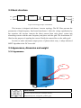
1
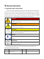
1 Manual Instruction
1.1 Symbols used in this manual
This manual contains important instructions for safety and operation which must be
understood and carefully followed during installation and maintenance of the equipment.
In order to reduce the risk of electric shock and to be sure that the equipment is correctly
installed and ready to operate, special safety symbols are used in the manual to highlight
potential safety risks or useful information. The symbols are the following:
DANGER!
DANGER indicates a hazardous situation which, if not avoided, will result
in death or serious injury.
WARNING!
WARNING indicates a hazardous situation which, if not avoided, could
result in death or serious injury.
CAUTION!
CAUTION indicates a hazardous situation which, if not avoided, could
result in minor or moderate injury.
NOTICE
NOTICE indicates a situation which, if not avoided, could result in property
damage.
Information
Information provides tips that are valuable for the optimal installation and
operation of your product.
This manual and machine may also use the following electrical symbols and
identification. Description as follows:
Symbol
Description
Symbol
Description
—
Continuous negative voltage pole
Direct current
-1-
+
Alternating current
On (Supply)
Earth (ground) TERMINAL
Off (Supply)
Protective conductor TERMINAL
Caution, risk of electric shock
Frame or chassis TERMINAL
Caution, hot surface
Continuous positive voltage pole
Caution, risk of danger
Caution, risk of electric shock.
Energy storage timed discharge
(time to be indicated adjacent to
the symbol)
Refer to the operating instructions
1.2 User group
Please read this manual thoroughly. This manual contains information about
EA3KLPV/EA4KLPV/ EA5KLPV single phase grid-connected inverter of transportation,
installation, operation, maintenance and troubleshooting.
1.3 Validity
This manual applies to EA3KLPV/EA4KLPV/ EA5KLPV grid-connected inverter.
2 Safety Instructions
¾ The inverter must be installed by a qualified electrician who is responsible for
observing existing standards and regulations.
¾ Read and understand all the instructions contained in this manual and become familiar
with the safety symbols in the relevant paragraphs before you install and operate the
equipment.
-2-
¾ The connection to the distribution grid must be done only after receiving approval
from the distribution utility as required by national and state interconnection
regulations, and can be done only by qualified personnel.
¾ Comply with all corresponding marks and symbols present on each device. During
operation, make sure that all covers and doors are closed.
DANGER!
Unauthorized removal of the necessary protections, improper use, wrong
installation or wrong operation may lead to serious damage to people and
objects.
Transport, handling, installation, start-up and maintenance must be performed
by qualified and trained personnel.
DANGER!
After disconnecting the inverter from distribution grid, wait for 60 seconds for
capacitors to discharge before servicing or touching any live part and electric
connection.
WARNING!
The installation must be performed in full compliance with national and local
standards and regulations.
WARNING!
When the photovoltaic array is exposed to light, it supplies a DC voltage to the
PCE. To ensure a safe work environment, keep the whole surface of the
photovoltaic panel covered with material opaque to solar radiation before
connecting panel to equipment.
WARNING!
Make sure the DC input voltage does not exceed 520V, or it may damage this
inverter permanently and cause other losses.
-3-
WARNING!
Do not change the internal components of the inverter without permission.
WARNING!
If the equipment is used in a manner not specified by the manufacturer, the
protection provided by the equipment may be impaired.
3 Product Description
3.1 Photovoltaic/PV grid-connected system
PV grid-connected system consists of PV modules, grid-connected inverters,
metering device and power distribution system (Figure 1).
The solar energy is converted into DC current by PV modules and then feeding into
the local power grid network by the grid-connected inverter which synchronizing the
frequency, phase and pure sine waveform with the power network.
PV modules
Combiner box
Inverter
Metering
Figure 1 PV grid-connected system
-4-
Power grid
3.2 Basic structure
PV+
EMI
DC/AC
BOOST
EMI
L
N
PV-
G
Figure 2 Working principle of EA3KLPV
This inverter is designed with boost+ inverter topology. The DC filter prevents the
penetration of high-frequency line-bound interference. After the voltage equalization by
the capacitor, the inverter converts the direct current from solar power system into
alternating current with the same frequency and phase with the grid. The downstream LC
filter has the purpose of equaling the current. Finally the current flows to the utility grid.
In order to make maximum output power of photovoltaic array, it adopt advanced
MPPT algorithm in the DC boost side.
3.3 Appearance, dimension and weight
3.3.1 Appearance
LCD
Button
Information
Inverter with 4 colors for customer choice.
Respectively are: red, green, yellow, gray
-5-
PV Input
RS485
Communication
Terminal
DC switch
AC Output
Figure 3
External Appearance of EA3KLPV/EA4KLPV/EA5KLPV
Information
Installation method as shown in the 5.5.1 of “Ⅰ”.
RS485
Communication
Terminal
PV Input
AC Output
DC switch
Figure 4
External Appearance of the special EA3KLPV
Information
Installation method as shown in the 5.5.1 of “Ⅱ”.
Information
The PV input has one channel of MPPT which consists of three pairs of
terminals, so there can be max three PV strings connecting to the channel.
-6-
3.3.2 Dimensions and weight
430
200
568
Figure 5
Dimensions of EA3KLPV/EA4KLPV/EA5KLPV
The dimensions of the EA3KLPV/ EA4KLPV/ EA5KLPV are 430mm ×568mm
×200mm (W×H×D). The inverter weighs approximately 25kg. Please take this dimension
and weight into consideration during shipping, moving and installation.
3.4 Technical data
EA3KLPV
Type
EA4KLPV
EA5KLPV
Specification
Input
Nominal DC voltage
400VDC
Operating voltage range
150V~500V
Max PV input voltage
520
PV short-circuit current
20A
22A
22A
Max DC current
18A
20A
20A
Max DC power
3.3kw
4.3kw
5.3kw
Peak DC short-circuit feedback current
159 A peak impulse (duration time 2ms)
DC to case insulation voltage
Basic insulation 1800Vdc/1min
MPPT
-7-
Full-load MPPT voltage range
180~420VDC
210~420VDC
250~420VDC
Number of MPP-Trackers
1
1
1
MPPT efficiency (static)
>99%
Output (AC)
Working manner
continuous
Output phase number
single phase and 3 line
Nominal AC power
3kw
Nominal AC voltage
230Vac
Nominal AC current
4kw
5kw
13.5A
18A
22A
Max allowable AC current
16A
20A
25A
Nominal frequency
50Hz
Distortion (THD)
<3% (nominal power)
Output voltage DC ponderance
<0.5%(nominal output power)
Power factor (cos phi)
>0.99
Output current limit
When overload or short circuit
Inverter short-circuit current
130 A peak impulse (duration time 2ms)
AC to case insulation voltage
Basic insulation 1500Vdc/1min
Efficiency
Max efficiency
97.5%
Euro efficiency
96.2%
96.3%
96.5%
General Requirements
Standby consumption
12w
Night consumption
0W
Grid connected method
Direct connect(transformerless)
Ingress protection
IP65
Protection degree
Type I
RS485 to DC input insulation voltage
Reinforce insulation 3000Vdc/1min
Mean Time Between Failures(MTBF)
40,000 hours
Working life
20 years
Protection
Reverse connect protection
Input protection
Short-circuit protection
DC to ground insulation resistance detecting and >800kohm
protection
Output protection
Short-circuit protection
Grid monitoring
Voltage monitoring,Frequency monitoring
Input lower /over-voltage protection points
150V/530V
Grid lower /over-voltage
protection points
TUV: DIN VDE
0126-1-1
184V/253V
G59/2
X
200V/253V
200V/253V
G83-1
207V/264V
X
X
AS4777
205V/265V
-8-
Grid lower
/over-frequency
protection points
TUV: DIN VDE
0126-1-1
50.2Hz/47.5Hz
G59/2
X
52.0Hz/47.0Hz
52.0Hz/47.0Hz
G83-1
50.5Hz/47.0Hz
X
X
52Hz/47.5Hz
AS4777
Residual current monitoring
Comply with DIN VDE 0126-1-1
Fault current monitoring
Comply with DIN VDE 0126-1-1
Anti-islanding protection
Comply with DIN VDE 0126-1-1
Standard
Safety
IEC 62109-1,IEC 62109-2
certification
VDE/TUV/CE
EMC
EN61000-6-1,EN61000-1-2;Class B
EMI
EN61000-6-3,EN61000-1-4
Functional safety and anti-islanding
DIN VDE0126-1-1/AS4777/G83-1/G59-2
Remark: Europe efficiency calculate :
η Euro = 0.03η 5% + 0.06η10% + 0.13η 20% + 0.10η 30% + 0.48η 50% + 0.20η100%
Others
Items
Specification
Remarks
Radiation noise
CISPR22 Class A
Conducted noise
CISPR22 Class A
AC short circuit protection
Yes(current limited)
Lightning resistant
1.2uS X 50uS 5kV
DC/AC to ground
ESD Protection
Case to operational part 15kV
System can work normally
Noise
<50dB 1m
5Hz 1G 30times at X・Y direction
Vibration resistance
10Hz 1G 30times at X・Y direction
JEC-5917
5Hz 0.5G 30times at Z direction
10Hz 0.5G 30times at Z direction
Durable years
Average temperature 25℃ 12H/day
20 years
Environmental conditions
Items
Specification
Operating temperature
-20℃~ +50℃
Altitude
2000 m
Relative humidity
4% ~ 100 %
Noise level
<50dB 1m
Cooling Method
Natural cooling
* Above data just for reference. If there is a change, please refer to the machine.
-9-
Remarks
4 Installation
4.1 Safety
DANGER! Danger to life due to fire or explosion!
Despite careful construction, electrical devices can cause fires.
• Do not mount the inverter on flammable construction materials.
• Do not install the inverter in areas where highly flammable materials are
stored.
• Do not install inverters in areas with a risk of explosion.
CAUTION! Risk of injury due to the heavy weight of the inverter.
•Take the weight of the inverter into account for transport.
• Select a suitable mounting location and mounting surface.
• When mounting the rear panel, use fastening material suitable for the
mounting surface.
• Two people are needed to mount the inverter.
CAUTION! Danger of burn injuries due to hot enclosure parts!
Mount the inverter in such a way that it cannot be touched
inadvertently.
4.2 Selecting the mounting location
Consider the following points when selecting where to install:
¾ The protection level of this product is IP65, so it can be installed outdoors.
¾ Vertical installation.
¾ Do not install horizontally.
¾ Select a well-ventilated location sheltered from direct sun radiation. Choose a
location that allows unobstructed airflow around the inverter.
¾ The operation will generate some noise (<50dB), so please install away from the
people living space.
¾ Mount on a solid surface. Ensure the installation place does not wobble.
- 10 -
¾ The machine should be installed in the reinforced concrete wall or metal wall that
can bear the weight of the inverter. It should not be installed in the wood to keep
from danger of fire.
¾ Height from ground level should be such as to ensure that the display and status
LEDs are easy to read.
¾ Ensure the temperature range can keep in the range (-25°C — +50°C)
¾ Allow sufficient room around the inverter to enable easy installation and removal
from the mounting surface.
¾ There must be sufficient clearance between the individual inverters so that the
¾ cooling air from the adjacent inverter is not drawn in.
NOTICE
Ambient temperature range shall be -20°C to +50°C. It will affect the
power output when the temperature exceeds the limit.
NOTICE
Environment humidity must be in the range of 4% ~ 100%.
4.3 Wall mounting
Included in the shipping package is a mounting kit with 6 screws and 6 wall plugs
provided for mounting the metal bracket to a concrete wall. The screws should be
mounted in the 6 holes present in the bracket (as Figure 5 shows).
After the bracket is secured to the wall, hang the inverter on the bracket. As shown
below.
Bracket
Rear panel
Figure 6
Installation for cabinet
- 11 -
The inverter needs to be lifted up and then slid down over the hooks making sure that
the connecting points in the bracket and in the back of the inverter engage properly.
5 Electrical Connection
5.1 General safety instruction
DANGER!
Improper operation during the wiring process can cause fatal injury to
operator or unrecoverable damage to the inverter.
Only qualified personnel can perform the wiring work.
DANGER!
Before you connect the inverter, disconnect the AC and DC sides from all
power sources and secure them against being inadvertently switched back on.
WARNING!
Always respect the nominal ratings of voltage and current specified in section
4 (Technical Data) when designing your system. Please observe these
considerations when designing the photovoltaic field:
Maximum DC voltage input to each MPPT circuit: 520 V
Maximum DC current input to each MPPT circuit: 18A for EA3KTLPV and
20A for EA4KLPV/ EA5KLPV
WARNING!
Check the national and local standard regulations to make sure that your
electrical installation design is in compliance with them.
NOTICE
All cables must be firmly attached, undamaged, properly insulated and
adequately dimensioned.
- 12 -
5.2 The electrical connection diagram overview
Inverter electrical connection includes PV side electrical connections, AC side
electrical connections and communication cable electrical connection.
No.
Item
Remarks
DC circuit breaker
Used as a protective device during electrical connection. User
must equips this device according to the maximum input voltage
and current. You must choose the external DC circuit breaker
whose rated current is 40A and the max breaking capacity can
reach more than 1kA.
B
PV arrays
There are three pairs of input terminals in one MPPT channel for
the inverter. The allowable maximum open-circuit voltage of PV
arrays is 520V. And the allowable maximum short-circuit currents
of the connected modules is 22A.
C
Remote PC
A
D
AC circuit breaker
E
Grid
User equips this device to monitor the state of the inverter.
Used as a protective device during electrical connection. You
must choose the external AC circuit breaker whose rated current
is 40A and the max breaking capacity can reach more than 2kA.
The PE cable should be connected reliably to the earth.
Rated voltage of each phase of the utility grid is 230V.
- 13 -
5.3 Cable requirements
All cables for PV power system are equipped with water-proof direct plug-in
connectors. You‘ll find these connectors in the package.
For electrical connection in the PV system described above, the cross section of all
cables used should not be smaller than the following requirements.
Terminals
AC Output
Wire Size
(mm)
DC Input 1
DC Input 2
DC Input 3
L
N
+
-
+
-
+
-
EA3KLPV
11
11
10
10
10
10
10
10
EA4KLPV
10
10
10
10
10
10
10
10
EA5KLPV
10
10
10
10
10
10
10
10
Model
AWG
There are three channels of DC input which can connect three PV strings. The red is
“+”, and the black is “-”. There is one channel of AC output, the red is L phase, the black
is N phase,and the yellow-green is PE.
NOTICE
The grid impedance of the AC cable must not exceed 1 Ohm. Otherwise, the
inverter will disconnect at full feed capacity due to excessive voltage at the
feed-in point.
5.4 Connection of the PV generator (DC)
5.4.1 DC input wiring
Positive
terminal
Negative
terminal
- 14 -
5.4.2 DC connection
Step 1: Assemble DC cable to connector at the inverter side. See “5.4.1 DC Input
Wiring”.
Step 2: Disconnect DC and AC circuit breakers.
Step 3: Check connection cable of one PV array string for correct polarity and that
the maximum input open circuit voltage does not exceed 520V.
Step 4: Measure DC voltage between positive terminal of the PV string and Earth
and DC voltage between negative terminal of the PV string and Earth. If the two voltages
are constant and not zero, there is an insulation failure somewhere in this PV string.
- 15 -
Step 5: Plug DC positive and negative connector into corresponding terminals. If it
makes a click sound, it means DC connector has attached to terminals.
Step 6: Link the rest of the two photovoltaic module strings in the same manner.
NOTICE
To create the sealing of the inverter, all the DC inputs that are not required
have to be closed as follows:
– Insert the sealing plugs provided into the DC plug connectors that are not
required. Do not insert the sealing plus into the DC inputs on the inverter.
– Insert the DC plug connectors with sealing plugs into the corresponding
DC inputs on the inverter.
5.5 Connecting inverter to AC grid
5.5.1 AC output wiring
NOTICE
As the series of products, in the 3KWpower section, there are two kinds
of AC output terminals, So,in the installation of EA3KLPV machine, please
install personnel to select the corresponding installation method
Ⅰ: Do not plug in AC output terminal installation method
NOTICE
The following installation method applicable to the series, with the
exception of the special EA3KLPV; External Appearance as shown in
Figure 3
- 16 -
Step 1: Unscrew AC output cover at the downside of the machine.
Step 2: Insert stripped AC cables of appropriate size into the cable glands. Fix the
phase cables into corresponding terminals with screwdriver according to marks. Fix
ground cable into the ground terminal.
- 17 -
Step 3: Screw the AC output cover.
Step 4: Tighten the cable gland in clockwise direction.
Ⅱ: Pluggable AC output terminal installation method
NOTICE
The following installation method is only applicable to the series of
special EA3KLPV ,External Appearance as shown in Figure 4.
- 18 -
Step 1: Put the wires through Screw Cap, Adapter Body of the AC female connector.
Keep the wire L, N, PE corresponding to 1、3、
of the AC male connector on the
inverter correctly.
1
3
L
N
PE
Wire red
Wire black
Wire yellow&green
Attention!
Please ensure the corresponding relationship between polarity
the core cable and the holes of the terminal is the correct
Step 2: Screw these components tightly after connecting the wires.
Step 3: Finally, connect AC female terminal to AC male terminal on inverter ,tighten
the cable and then screw them tightly together.
- 19 -
DANGER! Danger to life due to fire or explosion!
Despite careful construction, electrical devices can cause fires.
• Do not pull out the connector, when grid-connected inverter is working,
so as to avoid electric shock hazard.
• Do not immediately contact pin, when grid-connected inverter after
disconnection, there may be residual electricity,
5.5.2 AC connection
Step 1: Assembling AC cables to connector supplied. See “5.5.1 AC Output Wring”.
Step 2: Make sure that AC and DC circuit breaker are disconnected.
Step 3: Connect L, N to AC circuit breaker.
− Plug AC connector to corresponding AC terminals.
− Screw AC cables to AC circuit breaker.
Step 4: Connect PE to the ground.
Step 5: Connect AC circuit breaker to utility grid.
Step 6: Make sure that all AC cables are firmly installed.
NOTICE
Assignment of AC cables should be paid attention to, especially
“PE/GND” wire.
5.6 Connecting communication cable
5.6.1 Assembling the RS485 plug connector
Step 1: Make the communication cable through the waterproof ring, and then
connect the cables to the terminal.
- 20 -
1
Blank
2
B
3
A
4
GND
2. Fasten the waterproof ring and case.
3. Finally, match the finished terminal to the RS485 communication port on the
inverter’s case,then it is ready for communication.
5.6.2 Monitor system connection
The inverter provides RS485 interface to communicate with remote PC. User can
monitor the state of the inverter and observe current running information and history
record via this interface. Below is the method to install the monitoring system.
6 Switch on and off
6.1 Switch on
1. Finish the installation of the PV array, AC grid and the inverter according to the
introduction before.
2. Before switch on, checking whether AC voltage and DC voltage can meet the
requirement of the inverter
3. Switch on the DC breaker at first.
4. Then switch on the AC breaker.
5. When the environment conditions allow the inverter to work, the inverter will
automatically start up and connect the grid to generate power.
6. After the inverter works normally on grid, it can be left working itself without
human control. It can shut down when fault occurs and it can start automatically after the
fault is gone.
- 21 -
6.2 Switch off
1. When solar power was not enough to generate the power, the inverter will shut
down automatically.
2. If you need to shut down yourself, you can operate the inverter through the front
panel screen.
3. The process of emergency shutdown.
If you need shut down the inverter in emergency, first turn off the AC breaker, then
turn off the DC breaker, otherwise it may lead to the damage of the DC breaker and
danger to people. If any damage or loss occurs due to not following this requirement,
EAST POWER will not follow the warranty.
7 Troubleshooting
7.1 Troubleshooting of the LED indicator
Type of fault
Troubleshooting
LED indicators and LCD
1. Disconnect AC circuit breaker.
cannot be lit
2. Disconnect DC circuit breaker.
3. Check the polarity of DC input.
“RUN” indicator goes out
1. Disconnect AC circuit breaker.
2. Disconnect DC circuit breaker.
3. Check the correctness of electrical connection of inverter.
4. Check whether the voltage of DC input exceeds start-up voltage
of inverter.
5. If all above conditions are OK, please contact East.
“Fault” indicator is lit red.
1. There is a fault which is not removed yet.
2. Perform troubleshooting according to fault type in LCD screen.
See “7.2 Troubleshooting of Faults in LCD Screen”.
3. If it can’t be solved, please contact East.
- 22 -
7.2 Troubleshooting of faults in LCD screen
Type of fault
Explanation
Troubleshooting
PV OV
Overvoltage in PV input
1. Disconnect AC circuit breaker.
2. Disconnect DC circuit breaker.
3. Check the voltage of PV side.
4. Restart the inverter until the DC voltage
returns to allowable range.
BUS OVER/
RPH.OV
Overvoltage of the bus/
Overvoltage of grid voltage
RPH.UV
Under voltage of the grid
1. Disconnect AC circuit breaker.
2. Disconnect DC circuit breaker.
3. Check the voltage of grid side.
4. If local grid condition exceeds AC
requirements of inverter, reset the protecting
parameters. See “8.2.4 PARA. SET”.
And if local grid voltage exceeds the upper
limit value of “Vgrid-max”, or if local grid
voltage is under the lower limit value of
“Vgrid-min”, please contact your local
electricity company to adjust the grid
voltage.
5. If the fault still exists, please contact East.
RPH.OFR
Over-frequency in the grid
RPH.UFR
Under-frequency in the grid
1. Disconnect AC circuit breaker.
2. Disconnect DC circuit breaker.
3. Check the frequency of grid side.
4. If local grid condition exceeds AC demands
of inverter, reset the protective parameters.
See “8.2.4 PARA. SET”.
And if local grid frequency exceeds the
upper limit value of “Fgrid-max”, or if local
grid frequency is under the lower limit value
of “Fgrid-min”, please contact your local
electricity company to adjust the grid
frequency.
5. Close DC circuit breaker.
6. Close AC circuit breaker.
7. If the fault can’t be solved, please contact
East.
- 23 -
BOOST OT
R MO. OT/
Over- temperature in Boost
module
Over-temperature in the
inverter module
1. Check whether the installation place is OK.
2. Check whether AC output power exceeds
rated power too much.
3. Check the state of the fans.
4. Check whether there is some foreign body
blocking the air inlet and outlet. Clean air
grills of air vent.
RPH.OC
Over-current in the grid side
Check whether AC output power exceeds rated
power too much.
RPH.OL
Overload in the grid side
Check whether there is too much load in the
output grid.
NO GRID
/ISOLATED
The grid is not normal.
1. Check whether AC circuit breaker is off.
2. Check whether AC cables are all firmly
connected.
3. Check whether grid is cut off.
4. If all conditions are OK and this malfunction
still occurs in the LCD screen, please
contact East.
MO.FAULT
There is a fault in the module If this malfunction occurs, the reasons are very
of the inverter.
complicated.
1. Disconnect AC circuit breaker.
2. Disconnect DC circuit breaker.
3. Check the temperature of heat sink. If its
temperature exceeds 80℃, restart the
inverter until it recovers to environment
temperature.
5. Close DC circuit breaker.
6. Close AC circuit breaker.
7. If this malfunction happens again, please
contact us.
LEAKAGE C.
The leakage current is
abnormal.
PV NO EARTH
The insulation between the
PV and the Earth is
abnormal.
RELAY FAULT
The state of the relay in the
inverter is abnormal.
If the LCD shows these faults, there may be
something damaged in the inverter or the solar
modules. Then you’d better not touch any
component of the inverter, shutdown the
circuit-breaker or the disconnector
immediately and then contact us.
- 24 -
8 Operation Instructions
8.1 Front panel introduction
The front panel consists of LCD, state indicator and the button, by which we can set
the parameters and observe the operating status.
LCD display
Button
Indicator
Figure 9 LCD and Interface
8.2 Operation of LCD
8.2.1 RUN INFO.
1. Automatic screen saver interface, it displays the main
running parameter including input voltage, input
current, input power, grid voltage, grid current, grid
power and frequency. After 5 minutes, if there is no
operation, the LCD interface will automatically go into
the default interface. It contains running status,
generation power, the present time and date and also
the fault information.
2.Press “ENTER” into the control main menu
3. Select “RUN INFO”, press “ENTER” , you can check
the overall running information
- 25 -
4. It first shows the PV input parameters
5. Press , it displays the actual parameters of AC output
8.2.2 HISTORY
1. Enter the default main menu interface;
2.Press “ENTER”into the “control main menu;
3.Select “HISTORY”;
4. Press “ENTER”into the “History” menu
5. Fault history including present fault information and
history fault information。
6. The exact fault as below: DC over voltage, AC low
voltage, frequency abnormal, island effect,
temperature abnormal, DSP abnormal,
communication abnormal and so on.。
7. Press
to next page to see the information.
8. Press “ENTER”,showing the interface to clear
history information .
- 26 -
9. Select OK ,press “ENTER”, it will shows the input
code interface; 10. Input the correct password ,the history information
will be cleared ,please confirm it before the
operation。 8.2.3 POWER ON/OFF
1. Enter the default main menu interface;
2. Press “ENTER”into the “control main menu”; 3.Select “POWER ON/OFF”; 4. Press “ENTER” into the power off interface;
5. Press “ENTER”to power off.
- 27 -
NOTICE
In normal case, when the external condition is OK, the machine will start
by itself.
8.2.4 PARA. SET
1. Enter the default main menu interface;
2. Press“ENTER”into the “control main menu”;
3. Select “PARA. SET”;
4. Press “ENTER”;
5. The default password is month+date+time, six number,
eg: month and date is 2011-06-07, time is 15:23:11, so
the code is 060715;
6. press“ENTER”
7. Enter the parameter setting interface, you can set the
language, time, communication mode, protect
parameter, code and so on;
8. Select “language”, press “ENTER”into the language
setting interface. There are five kinds of language, you
can select the relative language, use the“ ”to find the
language you need and press “ENTER” to confirm.
9. Select “time set”, press “enter” into the time setting
interface, you can set the date and time;
- 28 -
10. Select “communication set”, press “ENTER”, you can
set the communication address and the baut rate;
11. Select “Protection set”, press “ENTER” into the
protection setting interface ,you can set the on-grid
voltage and the protect frequency;
12. Select “Code set”, press “ENTER “into the code
setting interface, you can set the password in order to
strengthen the safety of the system;
13. Select “return initial set”, press “ENTER” into the
initializing interface ,it can initialize the language,
time, date, communication ,protect parameter and so
on. All the record and fault information will be cleared
and return to the parameter set interface ,so please
think carefully to use the function of returning to the
factory value;
14. Press “ENTER” to select the data ,use the to add or
delete the value, after the set of the last value, press
“enter” to confirm;
15. When the value of the generation power on the LCD
is not the same with the outside metering device ,the
interface will change the generation value ; Notice
that when you select +,use
can change the +/-;
16. Generation power compensation=metering device
value-generation power value on the LCD;
NOTICE
The communication parameter is the most important parameter in the
inverters’ communication and the communication between the inverter
and the external monitor device.
- 29 -
8.2.5 PRODUCT INFO.
1. Enter the default main menu interface;
2. Press “ENTER” into the control main menu.
3. Select “product information”;
4. Press“ENTER”
5. The interface will display the company’s name, the product’s
type and software version.
9 Appendix
9.1 Packaging list
Check the packaging list for completeness and for any visible external damage.
Contact your dealer if anything is damaged or missing.
No
item
quantity/unit
1
PV Grid-connected inverter
1 set
2
User’s manual
1 pcs
3
Product warranty card
1 pcs
4
screws
6 pcs
5
PV input terminal
1 set
6
AC output terminal
1 set
Table1 Packaging list
- 30 -
remarks
9.2 Exclusion of liability
The content of these documents is periodically checked and revised, when necessary,
please call us or check our website for the latest information. However discrepancies
cannot be excluded. No guarantee is made for the completeness of these documents.
Please contact our company or distributors to get the latest version.
Guarantee or liability claims for damages of any kind are excluded if they are caused
by one or more of the following:
z Improper or inappropriate use or install of the product
z Installing or operating the product in an unintended environment
z Installing or operating the product when ignoring relevant safety regulations in the
deployment location
z Ignoring safety warnings and instructions contained in all documents relevant to the
product
z Installing or operating the product under incorrect safety or protection conditions
z Altering the product or supplied software without authority
z The product malfunctions due to operating attached or neighboring devices beyond
allowed limit values.
z In case of unforeseen calamity or force majeure.
- 31 -