1
To our customers,
Old Company Name in Catalogs and Other Documents
On April 1st, 2010, NEC Electronics Corporation merged with Renesas Technology
Corporation, and Renesas Electronics Corporation took over all the business of both
companies. Therefore, although the old company name remains in this document, it is a valid
Renesas Electronics document. We appreciate your understanding.
Renesas Electronics website: http://www.renesas.com
April 1st, 2010
Renesas Electronics Corporation
Issued by: Renesas Electronics Corporation (http://www.renesas.com)
Send any inquiries to http://www.renesas.com/inquiry.
Notice
1.
2.
3.
4.
5.
6.
7.
All information included in this document is current as of the date this document is issued. Such information, however, is
subject to change without any prior notice. Before purchasing or using any Renesas Electronics products listed herein, please
confirm the latest product information with a Renesas Electronics sales office. Also, please pay regular and careful attention to
additional and different information to be disclosed by Renesas Electronics such as that disclosed through our website.
Renesas Electronics does not assume any liability for infringement of patents, copyrights, or other intellectual property rights
of third parties by or arising from the use of Renesas Electronics products or technical information described in this document.
No license, express, implied or otherwise, is granted hereby under any patents, copyrights or other intellectual property rights
of Renesas Electronics or others.
You should not alter, modify, copy, or otherwise misappropriate any Renesas Electronics product, whether in whole or in part.
Descriptions of circuits, software and other related information in this document are provided only to illustrate the operation of
semiconductor products and application examples. You are fully responsible for the incorporation of these circuits, software,
and information in the design of your equipment. Renesas Electronics assumes no responsibility for any losses incurred by
you or third parties arising from the use of these circuits, software, or information.
When exporting the products or technology described in this document, you should comply with the applicable export control
laws and regulations and follow the procedures required by such laws and regulations. You should not use Renesas
Electronics products or the technology described in this document for any purpose relating to military applications or use by
the military, including but not limited to the development of weapons of mass destruction. Renesas Electronics products and
technology may not be used for or incorporated into any products or systems whose manufacture, use, or sale is prohibited
under any applicable domestic or foreign laws or regulations.
Renesas Electronics has used reasonable care in preparing the information included in this document, but Renesas Electronics
does not warrant that such information is error free. Renesas Electronics assumes no liability whatsoever for any damages
incurred by you resulting from errors in or omissions from the information included herein.
Renesas Electronics products are classified according to the following three quality grades: “Standard”, “High Quality”, and
“Specific”. The recommended applications for each Renesas Electronics product depends on the product’s quality grade, as
indicated below. You must check the quality grade of each Renesas Electronics product before using it in a particular
application. You may not use any Renesas Electronics product for any application categorized as “Specific” without the prior
written consent of Renesas Electronics. Further, you may not use any Renesas Electronics product for any application for
which it is not intended without the prior written consent of Renesas Electronics. Renesas Electronics shall not be in any way
liable for any damages or losses incurred by you or third parties arising from the use of any Renesas Electronics product for an
application categorized as “Specific” or for which the product is not intended where you have failed to obtain the prior written
consent of Renesas Electronics. The quality grade of each Renesas Electronics product is “Standard” unless otherwise
expressly specified in a Renesas Electronics data sheets or data books, etc.
“Standard”:
8.
9.
10.
11.
12.
Computers; office equipment; communications equipment; test and measurement equipment; audio and visual
equipment; home electronic appliances; machine tools; personal electronic equipment; and industrial robots.
“High Quality”: Transportation equipment (automobiles, trains, ships, etc.); traffic control systems; anti-disaster systems; anticrime systems; safety equipment; and medical equipment not specifically designed for life support.
“Specific”:
Aircraft; aerospace equipment; submersible repeaters; nuclear reactor control systems; medical equipment or
systems for life support (e.g. artificial life support devices or systems), surgical implantations, or healthcare
intervention (e.g. excision, etc.), and any other applications or purposes that pose a direct threat to human life.
You should use the Renesas Electronics products described in this document within the range specified by Renesas Electronics,
especially with respect to the maximum rating, operating supply voltage range, movement power voltage range, heat radiation
characteristics, installation and other product characteristics. Renesas Electronics shall have no liability for malfunctions or
damages arising out of the use of Renesas Electronics products beyond such specified ranges.
Although Renesas Electronics endeavors to improve the quality and reliability of its products, semiconductor products have
specific characteristics such as the occurrence of failure at a certain rate and malfunctions under certain use conditions. Further,
Renesas Electronics products are not subject to radiation resistance design. Please be sure to implement safety measures to
guard them against the possibility of physical injury, and injury or damage caused by fire in the event of the failure of a
Renesas Electronics product, such as safety design for hardware and software including but not limited to redundancy, fire
control and malfunction prevention, appropriate treatment for aging degradation or any other appropriate measures. Because
the evaluation of microcomputer software alone is very difficult, please evaluate the safety of the final products or system
manufactured by you.
Please contact a Renesas Electronics sales office for details as to environmental matters such as the environmental
compatibility of each Renesas Electronics product. Please use Renesas Electronics products in compliance with all applicable
laws and regulations that regulate the inclusion or use of controlled substances, including without limitation, the EU RoHS
Directive. Renesas Electronics assumes no liability for damages or losses occurring as a result of your noncompliance with
applicable laws and regulations.
This document may not be reproduced or duplicated, in any form, in whole or in part, without prior written consent of Renesas
Electronics.
Please contact a Renesas Electronics sales office if you have any questions regarding the information contained in this
document or Renesas Electronics products, or if you have any other inquiries.
(Note 1) “Renesas Electronics” as used in this document means Renesas Electronics Corporation and also includes its majorityowned subsidiaries.
(Note 2) “Renesas Electronics product(s)” means any product developed or manufactured by or for Renesas Electronics.
User’s Manual
C Compiler Package
for 740 Family V.1.01
User’s Manual
Rev.1.01 2007.06
Notes regarding these materials
1. This document is provided for reference purposes only so that Renesas customers may select the appropriate
Renesas products for their use. Renesas neither makes warranties or representations with respect to the
accuracy or completeness of the information contained in this document nor grants any license to any
intellectual property rights or any other rights of Renesas or any third party with respect to the information in
this document.
2. Renesas shall have no liability for damages or infringement of any intellectual property or other rights arising
out of the use of any information in this document, including, but not limited to, product data, diagrams, charts,
programs, algorithms, and application circuit examples.
3. You should not use the products or the technology described in this document for the purpose of military
applications such as the development of weapons of mass destruction or for the purpose of any other military
use. When exporting the products or technology described herein, you should follow the applicable export
control laws and regulations, and procedures required by such laws and regulations.
4. All information included in this document such as product data, diagrams, charts, programs, algorithms, and
application circuit examples, is current as of the date this document is issued. Such information, however, is
subject to change without any prior notice. Before purchasing or using any Renesas products listed in this
document, please confirm the latest product information with a Renesas sales office. Also, please pay regular
and careful attention to additional and different information to be disclosed by Renesas such as that disclosed
through our website. (http://www.renesas.com )
5. Renesas has used reasonable care in compiling the information included in this document, but Renesas
assumes no liability whatsoever for any damages incurred as a result of errors or omissions in the information
included in this document.
6. When using or otherwise relying on the information in this document, you should evaluate the information in
light of the total system before deciding about the applicability of such information to the intended application.
Renesas makes no representations, warranties or guaranties regarding the suitability of its products for any
particular application and specifically disclaims any liability arising out of the application and use of the
information in this document or Renesas products.
7. With the exception of products specified by Renesas as suitable for automobile applications, Renesas
products are not designed, manufactured or tested for applications or otherwise in systems the failure or
malfunction of which may cause a direct threat to human life or create a risk of human injury or which require
especially high quality and reliability such as safety systems, or equipment or systems for transportation and
traffic, healthcare, combustion control, aerospace and aeronautics, nuclear power, or undersea communication
transmission. If you are considering the use of our products for such purposes, please contact a Renesas
sales office beforehand. Renesas shall have no liability for damages arising out of the uses set forth above.
8. Notwithstanding the preceding paragraph, you should not use Renesas products for the purposes listed below:
(1) artificial life support devices or systems
(2) surgical implantations
(3) healthcare intervention (e.g., excision, administration of medication, etc.)
(4) any other purposes that pose a direct threat to human life
Renesas shall have no liability for damages arising out of the uses set forth in the above and purchasers who
elect to use Renesas products in any of the foregoing applications shall indemnify and hold harmless Renesas
Technology Corp., its affiliated companies and their officers, directors, and employees against any and all
damages arising out of such applications.
9. You should use the products described herein within the range specified by Renesas, especially with respect
to the maximum rating, operating supply voltage range, movement power voltage range, heat radiation
characteristics, installation and other product characteristics. Renesas shall have no liability for malfunctions or
damages arising out of the use of Renesas products beyond such specified ranges.
10. Although Renesas endeavors to improve the quality and reliability of its products, IC products have specific
characteristics such as the occurrence of failure at a certain rate and malfunctions under certain use
conditions. Please be sure to implement safety measures to guard against the possibility of physical injury, and
injury or damage caused by fire in the event of the failure of a Renesas product, such as safety design for
hardware and software including but not limited to redundancy, fire control and malfunction prevention,
appropriate treatment for aging degradation or any other applicable measures. Among others, since the
evaluation of microcomputer software alone is very difficult, please evaluate the safety of the final products or
system manufactured by you.
11. In case Renesas products listed in this document are detached from the products to which the Renesas
products are attached or affixed, the risk of accident such as swallowing by infants and small children is very
high. You should implement safety measures so that Renesas products may not be easily detached from your
products. Renesas shall have no liability for damages arising out of such detachment.
12. This document may not be reproduced or duplicated, in any form, in whole or in part, without prior written
approval from Renesas.
13. Please contact a Renesas sales office if you have any questions regarding the information contained in this
document, Renesas semiconductor products, or if you have any other inquiries.
For inquiries about the contents of this document or product, fill in the text file the installer generates in the following directory and email to your
local distributor.
\SUPPORT\Product-name\SUPPORT.TXT
Renesas Tools Homepage
http://www.renesas.com /tools
z Active X, Microsoft, MS-DOS, Visual Basic, Visual C++, Windows and Windows NT are either registered trademarks or trademarks of
Microsoft Corporation in the United States and other countries.
z HP-UX is a registered trademark of Hewlett-Packard Company.
z Sun, Java and all Java-based trademarks and logos are trademarks or registered trademarks of Sun Microsystems, Inc. in the U.S. or other
countries, and are used under license.
z UNIX is a registered trademark of The Open Group in the United States and other countries.
z IBM and AT are registered trademarks of International Business Machines Corporation.
z HP9000 is a product name of Hewlett-Packard Company.
z SPARC and SPARCstation are registered trademarks of SPARC International, Inc.
z Intel and Pentium are registered trademarks of Intel Corporation.
z i386, i486, and MMX are trademarks of Intel Corporation.
z Adobe and Acrobat are registered trademarks of Adobe Systems Incorporated.
z Netscape and Netscape Navigator are registered trademarks of Netscape Communications Corporation in the U.S. and other countries.
z All other brand and product names are trademarks, registered trademarks or service marks of their respective holders.
Contents
PREFACE .................................................................................................................................. 8
1.
OVERVIEW ....................................................................................................................... 9
2.
QUICK TOUR .................................................................................................................. 10
3.
2.1.
CREATING A NEW PROJECT ...................................................................................... 10
2.2.
CREATING AND REGISTERING A FILE........................................................................ 13
2.3.
BUILDING A PROJECT ............................................................................................... 16
2.4.
STARTING THE DEBUGGER ....................................................................................... 16
2.4.1.
Debugging a Program ............................................................................................. 17
2.4.2.
Executing up to the main() Function ..................................................................... 18
2.4.3.
Confirming Interrupt Generation.......................................................................... 19
CREATE A NEW PROJECT ........................................................................................... 21
3.1.
4.
5.
6.
A NEW PROJERCT ..................................................................................................... 21
EDITING THE PROJECT............................................................................................... 27
4.1.
EDITING OPTIONS ..................................................................................................... 27
4.1.1.
Setting the Project Options .................................................................................... 28
4.2.
SETTING THE ICC740 OPTIONS ................................................................................ 29
4.2.1.
Registering a Header File ...................................................................................... 30
4.2.2.
Making the List File ............................................................................................... 31
4.3.
SETTING THE A740 OPTIONS .................................................................................... 31
4.3.1.
Making the List File ............................................................................................... 32
4.4.
SETTING THE XLINK OPTIONS ................................................................................ 33
DEVELOPING A PROJECT ........................................................................................... 35
5.1.
CREATING AND REGISTERING THE SOURCE FILES ................................................... 35
5.2.
ALTERING THE MEMORY MAP .................................................................................... 35
5.3.
CHANGING THE MEMORY MAP ................................................................................... 36
BUILDING A PROJECT ................................................................................................. 37
6.1.
ERRORS IN THE C COMPILER ICC740 AND THE ASSEMBLER A740 .......................... 37
6.2.
ERRORS IN THE LINKER XLINK............................................................................... 37
6.3.
NOTES FOR THE LINKER XLINK .............................................................................. 39
4
7.
DEBUGGING A PROJECT............................................................................................. 41
8.
CREATING A HEX FILE................................................................................................ 42
9.
NOTES TO BE TAKEN WHEN UPGRADING REVISIONS ........................................ 43
9.1.
UPGRADING FROM V.1.01 RELEASE 01..................................................................... 43
9.2.
CONVERTING THE PROJECTS CREATED WITH V.1.01 RELEASE 01 ........................... 43
10.
EDITING CSTARTUP.S31 AND LNK740.XCL ......................................................... 46
10.1.
EDITING CSTARTUP.S31 ............................................................................................ 46
10.1.1.
Changing the Stack Page ....................................................................................... 46
10.1.2.
Changing the Interrupt Vector Area ..................................................................... 46
10.2.
EDITING THE LNK740.XCL FILE ................................................................................ 47
10.2.1.
Changing the Stack Area ....................................................................................... 48
10.2.2.
Changing the Beginning Address of Page 0.......................................................... 48
10.2.3.
Changing the Ending Address of Page N .............................................................. 49
10.2.4.
Changing the ROM Area Address ......................................................................... 49
10.2.5.
Changing the Interrupt Vector Area ..................................................................... 50
10.2.6.
Deleting the Library ............................................................................................... 50
10.2.7.
Altering the lnk740.xcl File..................................................................................... 51
5
Figure of Contents
FIGURE 1 NEW PROJECT WORKSPACE DIALOG BOX ..................................................................... 10
FIGURE 2 [NEW PROJECT] WIZARD ............................................................................................. 11
FIGURE 3 DISPLAYING THE CONFIGURATION AND SESSION ......................................................... 12
FIGURE 4 THE PROJECTS TAB OF THE WORKSPACE WINDOW ...................................................... 12
FIGURE 5 PROJECT TAB WITH FILES REGISTERED ........................................................................ 13
FIGURE 6 BUILD, BUILD ALL, AND BUILD FILE BUTTON ............................................................. 16
FIGURE 7 DISPLAYING THE SESSION ........................................................................................... 16
FIGURE 8 INIT DIALOG BOX OF 740 SIMULATOR .......................................................................... 16
FIGURE 9 PROJECT TAB TO WHICH THE DOWNLOAD MODULES IS ADDED .................................... 17
FIGURE 10 PROJECT TAB AFTER DOWNLOADING A PROGRAM....................................................... 17
FIGURE 11 DISPLAYING CSTARTUP.S31 AFTER RESET .................................................................. 18
FIGURE 12 SETTING A BREAKPOINT ............................................................................................. 18
FIGURE 13 DEBUG RUN TOOLBAR ............................................................................................... 18
FIGURE 14 STOPPING WITH A BREAKPOINT .................................................................................. 19
FIGURE 15 C WATCH WINDOW ..................................................................................................... 19
FIGURE 16 NEW PROJECT WORKSPACE DIALOG BOX ................................................................... 21
FIGURE 17 [NEW PROJECT] WIZARD : STEP 1.............................................................................. 22
FIGURE 18 [NEW PROJECT] WIZARD : STEP 2.............................................................................. 22
FIGURE 19 [NEW PROJECT] WIZARD : STEP 3.............................................................................. 23
FIGURE 20 [NEW PROJECT] WIZARD : STEP 4.............................................................................. 23
FIGURE 21 [NEW PROJECT] WIZARD : STEP 5.............................................................................. 24
FIGURE 22 [TOOLCHAIN] DIALOG BOX ........................................................................................ 27
FIGURE 23 [TOOLCHAIN] DIALOG BOX : CATEGORY:SOURCE ON THE C TAB ................................ 30
FIGURE 24 [TOOLCHAIN] DIALOG BOX : CATEGORY:LIST ON THE C TAB...................................... 31
FIGURE 25 [TOOLCHAIN] DIALOG BOX : CATEGORY:LIST ON THE ASSEMBLY TAB ....................... 32
FIGURE 26 LINK TAB ................................................................................................................... 34
FIGURE 27 EDITING CATEGORY:MEMORY .................................................................................... 35
FIGURE 28 [MODIFY SEGMENT]DIALOG BOX .............................................................................. 36
FIGURE 29 BUILD, BUILD ALL, AND BUILD FILE BUTTON ........................................................... 37
FIGURE 30 SELECTING THE SESSION........................................................................................... 41
FIGURE 31 INITIALIZATION DIALOG BOX OF 740 SIMULATOR....................................................... 41
FIGURE 32 CATEGORY:OUTPUT ................................................................................................... 42
FIGURE 33 CHANGE TOOLCHAIN VERSION SUMMARY ................................................................. 43
FIGURE 34 SETTINGS MADE IN THE LNK740.XCL FILE AFTER TOOLCHAIN CHANGE .................... 44
6
FIGURE 35 CATEORY:MEMORY..................................................................................................... 45
Table of Contents
TABLE 1 CONFIGURATION AND SESSION ...................................................................................... 12
TABLE 2 THE GENERATED SOURCE FILE ..................................................................................... 24
TABLE 3 CONFIGURATION AND SESSION ...................................................................................... 26
TABLE 4 CPU TAB ........................................................................................................................ 28
TABLE 5 THE LARGE MODEL AND THE TINY MODEL ..................................................................... 28
TABLE 6 C TAB ............................................................................................................................. 29
TABLE 7 DEFAULT OPTIONS OF THE ICC740............................................................................... 29
TABLE 8 ASSEMBLY TAB............................................................................................................... 31
TABLE 9 DEFAULT OPTIONS OF THE A740................................................................................... 32
TABLE 10 LINK TAB ..................................................................................................................... 33
TABLE 11 DEFAULT OPTIONS OF XLINK..................................................................................... 33
TABLE 12 CONTENTS OF TYPE OF OUTPUT FILE .......................................................................... 42
TABLE 13 ITEMS TO EDIT IN CSTARTUP.S31................................................................................. 46
TABLE 14 ITEMS TO EDIT IN LNK740.XCL .................................................................................... 47
7
Preface
Before reading this user’s manual, please read the release notes included with your product.
Product configuration, product handling, precautions and other important information are written
in it.
Target reader
This user’s manual is written for:
• Those who have experience in developing and debugging embedded application programs in
C language
• Those who use High-performance Embedded Workshop for the first time
Reference manuals
For more information about the terms used and the functions of High-performance
Embedded Workshop and details on how to use it, please refer to the manual given below.
This manual can also be consulted on-line.
High-performance Embedded Workshop V.4.02 User’s Manual
For more information about the terms used and the functions of the C compiler ICC740
from LAR Systems (hereafter referred to as the ICC740), and for details on how to use it,
please refer to the PDF manual included with the ICC740.
8
1. Overview
The C Compiler Package for 740 Family is a development environment system that has
been realized by combining the ICC740 and the High-performance Embedded Workshop,
providing a powerful support for developing programs in C and assembly languages.
The following items of software are included in the C Compiler Package for 740 Family.
• SC74
This is a source file converter that allows you to convert the source files created for the
Assembler Package for 740 Family into the source file format of the assembler A740
included with the ICC740. This software is outside the scope of technical support by
Renesas. For details on how to use the SC74, please refer to the included file license.txt.
This user’s manual describes how to install each tool in your computer, and details on how
to develop ICC740 projects in the High-performance Embedded Workshop.
9
2. Quick Tour
This chapter explains how to develop application programs using ICC740 through a quick
tour. Each procedure is detailed in Chapter 3 and those that follow.
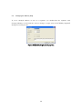
2.1.
Creating a New Project
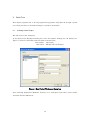
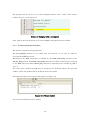
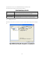
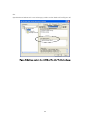
We will create a new workspace.
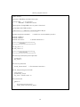
In the New Project Workspace dialog box of the C Compiler Package for 740 Family (see
Figure 1), select a CPU family and tool chain as shown below.
CPU family: 740 Family
Tool chain: IAR ICC740 (740 Family)
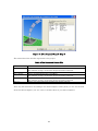
Figure 1 New Project Workspace dialog box
After selecting Application (Enhance Version), set a workspace name and a project name
and then click the OK button.
10
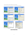
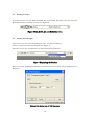
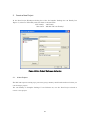
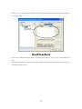
Use the New Project wizard (see Figure 2) to create a project.
In step 3 of the New Project wizard, select the check box labeled “740 Simulator.”
(1) Step 1
(2) Step 2
(3) Step 3
(4) Step 4
(5) Step 5
(6) Summary
Figure 2 [New Project] Wizard
11
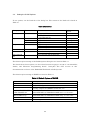
The C Compiler Package for 740 Family may be used to create the configurations and
sessions described Table 1.
Table 1 Configuration and Session
Configuration
Debug
Release
This is a configuration for Debug.
This is a configuration for Release.
Session
DefaultSession
Session740_Simulator
This is a session with no targets selected.
This is a session for 740 Simulator.
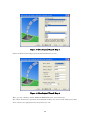
When you create a new workspace, you will have Debug and DefaultSession preselected for
the configuration and session, respectively (see Figure 3).
Figure 3 Displaying the configuration and session
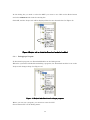
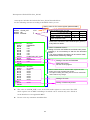
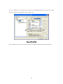
Furthermore, the Projects tab of the Workspace window will be displayed as shown below
(see Figure 4).
Figure 4 the Projects tab of the Workspace window
12
2.2.
Creating and Registering a File
We’ll create a source program. This time we use tutor3.c present in the SmpTw74 folder.
Copy tutor3.c to your project folder.
The SmpTw74 folder is created in the folder in which you installed ICC740 (normally
\Program Files\IAR Systems\ew23\740).
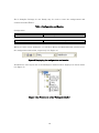
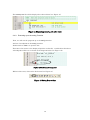
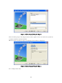
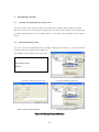
Simply because you placed a file in the project folder does not mean that you’ll have
registered it. So use Add Files on the Project menu to register (see Figure 5).
Figure 5 Project tab with files registered
Furthermore, correct a file proj_1.c and a file intf.c as shown below. Double-click on a file
to launch the editor.
correction of a file proj_1.c
#include <intr740.h>
void tutor3( void );
void main(void)
{
tutor3();
}
correction of a file intf.c
/*
void interrupt[0] I_BRK(void){
}
*/
void interrupt[2] I_AD_SIO3T(void){
13
tutor3.c:
The source file tutor3.c was derived from the sample program of IAR Systems by altering it
for use with 740 Simulator. Processing by this program and the source code of it are shown
below.
Processing
The program comprises an infinite loop in a while statement of the tutor3() function.
The variable my_char assumes values ‘a’ to ‘z’ at random depending on the function.
When the variable my_char assumes the value ‘i’, a BRK instruction interrupt is generated
by the function.
The function brk_interrupt() is executed by a BRK instruction interrupt, setting the variable
my_char to ‘.’. The statement interrupt[0x00] of this function sets the address of the function
brk_interrupt() in the BRK instruction interrupt vector for the 3803 group.
Thereafter, processing in an infinite loop of the main function is repeated.
14
Source program tutor3.c
/*----------------------------------------------------* File: tutor3.c
*
* Purpose: Handling real time interrupts
*
* Usage: ICC
-r -L -q tutor3.c
*
XLINK -r -f <link file> tutor3
*
* Description: Using BRK vector to print a character
*
* Copyright 1997 IAR Systems
*
* $Id: tutor3.c 1.3 1998/01/15 09:24:55Z Laban Exp $
*-----------------------------------------------------*/
#pragma language=extended
#include <stdlib.h>
#include <stdio.h>
#include "intr740.h"
/* enable use of extended keywords */
/* include intrinsics */
/**********************************
*
Variables
*
**********************************/
char my_char = '*';
int call_count = 0;
/**********************************
*
Start of code
*
**********************************/
void interrupt [0x00] brk_interrupt(void)
{
// putchar('I');
my_char='.';
}
void execute_brk(void)
{
break_instruction();
}
/* Use intrinsic function */
void do_foreground_process(void)
{
call_count++;
// putchar(my_char);
my_char = rand() % 26 + 'a';
}
void tutor3(void)
{
while (1)
{
do_foreground_process();
if (my_char=='i') execute_brk();
}
}
15
2.3.
Building a Project
To build a project, use the Build, the Build All, or the Build File button. We will select the
Build All button by clicking on it here (see Figure 6).
Figure 6 Build, Build All, and Build File button
2.4.
Starting the Debugger
If no more errors are found in building a project, you now can debug it.
Select a session to launch the debugger (see Figure 7).
This time we use the 740 Simulator, so select Session740_Simulator.
Figure 7 Displaying the Session
When you select Session740_Simulator, the dialog box shown below will be displayed (see
Figure 8).
Figure 8 Init dialog box of 740 Simulator
16
In this dialog box you need to select the MCU you want to use. Click on the Refer button
and select M38000.sfr file from the ensuing list.
Click OK, and the Project tab will be displayed like the one shown below (see Figure 9).
Figure 9 Project tab to which the Download modules is added
2.4.1. Debugging a Program
To download a program, use Download Modules on the Debug menu.
When the system has finished downloading a program, the “Download modules” icon on the
Projects tab changes shape (see Figure 10).
Figure 10 Project tab after downloading a program
Before you can run a program, you must first reset the CPU.
Choose Reset CPU on the Debug menu.
17
The cstartup.s31 file will be displayed as shown below (see Figure 11).
Figure 11 Displaying cstartup.s31 after reset
2.4.2. Executing up to the main() Function
First, we will run the program up to the main() function.
And set a breakpoint in the main() function.
Double-click on main.c to open the file.
Then move the mouse to the displayed position on line No. 7 and double-click there.
A breakpoint will be set as shown in the diagram below (see Figure 12).
Figure 12 Setting a breakpoint
While in this state, click on the Go button (see Figure 13).
Figure 13 Debug Run toolbar
18
The program will be run way up to this breakpoint position, and a yellow arrow will be
added to line No. 7 (see Figure 14).
Figure 14 Stopping with a breakpoint
Next, click on the Step In button. You will see tutor3.c file displayed in the window.
2.4.3. Confirming Interrupt Generation
We will now confirm interrupt generation.
The brk_interrupt() function is not called from any function. It can only be called by
executing the BRK instruction.
Execution of the BRK instruction is handled by the break_instruction() function in the
execute_brk() function. This break_instruction() function is an inline function that is replaced
by the BRK instruction. The execute_brk() function is called when the variable my_char is
set to ‘i.’
The value of the variable my_char may be watched in the C Watch window. To open this
window, choose the Symbol and the C Watch on the View menu.
The C Watch window shown below will appear (see Figure 15).
Figure 15 C Watch window
You select the Global tab in this window.
19
Set a breakpoint in the line No. 37 and No. 57 in the file tutor3.c and click the Go button
several times. Then, when the variable my_char is set to ‘i’ and is clicked the Go button, a
yellow arrow will be added to the line No. 37. This allows you to confirm that an interrupt
has been generated.
We are now finished with a quick tore.
20
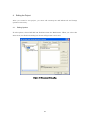
3. Create a New Project
In the New Project Workspace dialog box of the C Compiler Package for 740 Family (see
Figure 1), select a CPU family and tool chain as shown below.
CPU family: 740 Family
Tool chain: IAR ICC740 (740 Family)
Figure 16 New Project Workspace dialog box
3.1.
A New Projerct
The ICC740 requires setting up a processor group, memory model and stack area before you
can develop a project.
For 740 Family C Compiler Package V.1.01 Release 02, use the New Project wizard to
create a new project.
21
Figure 17 [New Project] Wizard : Step 1
Select the CPU series and group of the microcomputer you use.
Figure 18 [New Project] Wizard : Step 2
Here, you set a memory model, RAM and ROM addresses, and a stack size.
The values shown here represent the minimum memory size case of each CPU group. Alter
these values to be appropriate for the product you use.
22
Figure 19 [New Project] Wizard : Step 3
Select the debug target. The diagram shown above applies to the case where the system has
a compact emulator already installed.
When you select the debug target, the dialog box shown below is displayed.
Figure 20 [New Project] Wizard : Step 4
Set a configuration name.
23
Figure 21 [New Project] Wizard : Step 5
The wizard here lists the files registered to the project.
Table 2 The Generated Source File
File
cstartup.s31
intf.c
mcu_def.inc
sfr_3803h.h
proj_1.c
Contents
This is a start up file.
The content of step 1 of the New Project wizard is reflected.
This is a template file for interrupt functions.
This is an information file to the MCU.
The content of step 1 of the New Project wizard is reflected.
This is a SFR header file to the MCU.
The content of step 1 of the New Project wizard is reflected.
This is a C source file that includes the main() function.
Alter any file listed here according to the microcomputer and system you use. For details
about the microcomputer you use, refer to the data sheet of your microcomputer.
24
Description of Include File (mcu_def.inc)
cstartup.s31 includes the include file (mcu_def.inc) described here.
Set the following contents according to the MCU which you use.
Setting value of CPU mode register (address003B16)
#define CPUM_INIT
#define QZ
#define IDCODE
Setting of MCU which you Use
4CH
1
0
QZMACRO
RSEG
BLKB
BLKB
BLKB
BLKB
BLKB
BLKB
RSEG
BYTE
RSEG
BLKB
ENDM
MACRO
RESERVE1
01H
01H
01H
01H
01H
01H
FUNCTION_SET_ROM
0FFH
RESERVE2
01H
IDCODEMACRO
RSEG
BYTE
BYTE
BYTE
BYTE
BYTE
BYTE
BYTE
ROMCP:
BYTE
ENDM
MACRO
ID_CODE
0FFH
0FFH
0FFH
0FFH
0FFH
0FFH
0FFH
QZ
IDCODE
Mask ROM version
0
0
QzROM version
1
0
Flash version or versions
0
1
which require ID code
* Setting value may be different depending on MCUs.
Refer to the comment of the include file (mcu_def.inc)
every MCU for details.
<Macro of QzROM version>
Setting of function set ROM area and ROM code protect
Basically, it is not necessary to alter the line describes
BLKB.
* The object including this setting can be used for mask
ROM version without any change.
Setting of function set ROM data
ROM code protect
Not set on the program
<Macro of flash version or versions which require ID code>
Setting of ID code and ROM code protect
* The object including this setting can be used for mask ROM
version without any change.
Setting of ID code
Setting of ROM code protect
0FFH
<Notes>
z
The value of “CPUM_INIT” is set in the CPU mode register at reset start. The CPU
mode register has an MCU including a bit which can be written only once. Check it
in the datasheet of an applicable MCU.
z
Do not write any comment on #define line.
25
Description of Interrupt Function File (intf.c)
The interrupt function file describes an interrupt function which individual MCU has. A
program of the interrupt function to be used can be described and used on this file. If
necessary, please add it to the project file.
void interrupt[0] BRK(void){
}
void interrupt[2] AD_SIO3T(void){
}
Interrupt function name
void interrupt[4] Int4_CNTR2(void){
}
:
Offset value from the first address of the interrupt vector
:
The C Compiler Package for 740 Family may be used to create the configurations and
sessions described Table 3.
Table 3 Configuration and Session
Configuration
Debug
Release
Debug_740_Simulator
This is a configuration for Debug.
This is a configuration for Release.
This is a configuration for 740 Simulator.
The content of step 4 of the New Project wizard is
reflected.
Session
DefaultSession
Session740_Simulator
Session740_Compact_Emulator
This is a session with no targets selected.
This is a session for 740 Simulator.
The content when the 740 Simulator is selected in
step 3 of the New Project wizard.
This is a session for 740 Compact Emulator.
The content when the 740 Compact Emulator is
selected in step 3 of the New Project wizard.
26
4. Editing the Project
After you created a new project, you must edit cstartup.s31 and lnk740.xcl and change
options as necessary.
4.1.
Editing Options
To edit options, choose IAR ICC740 Toolchain from the Build menu. When you select this
menu item, the Toolchain dialog box shown in Figure 22 is activated.
Figure 22 [Toolchain] Dialog Box
27
4.1.1. Setting the Project Options
Using the [New Project] wizard, set the content of Table 4 on the CPU tab of the dialog box.
Table 4 CPU tab
Item
Processor
configuration
Memory model
Contents
• 740 with MUL/DIV instruction (It is a general CPU)
• 740 without MUL/DIV instruction
• 740 with MUL/DIV and extended data memory access
• Large
• Tiny
• 0 page only
Relevant
option
-v0
-v1
-v2
-ml
-mt
-mt
• The Large model and the Tiny model
The Large and the Tiny models differ in variable locations.
In the Large model, variables are located at the address 0x100 or more, whereas in the Tiny
model, variables are located at addresses from 0x00 to 0xFF.
If variables in the Large model need to be located at addresses from 0x00 to 0xFF, use the
extension keyword zpage. In assemble source programs, the operand zp: may be used to
access those addresses for the purpose of reduced code size.
If variables in the Tiny model need to be located at the address 0x100 or more, use the
extension keyword npage. In assemble source programs, the operand np: should be used to
access those addresses. Unless the operand np: is used, an error will occur when linking.
Table 5 the Large model and the Tiny model
item
variable locations
Located at the address
0x100 or more in C
Large model
0x100 or more
Located at the address
from 0x00 to 0xFF in C
Defined using zpage.
zpage int v3;
extern zpage int v4;
Accessed the address
0x100
or
more
in
Assembler
Accessed the address from
0x00 to 0xFF in Assembler
Tiny model
from 0x00 to 0xFF
Defined using npage.
npage int v1;
extern npage int v2;
The operand zp: may be
used.
lda np:v1
The operand zp: may be
used for the purpose of
reduced code size.
lda zp:v3
The extension keywords zpage and npage can be specified in global variables, auto
variables, and parameters to functions.
28
4.2.
Setting the ICC740 Options
To set options, use the C tab of the dialog box. The content of the C tab is listed in Table 6.
Table 6 C Tab
Category
Source
Object
Show entries for
Include file
directories
Defines
Undefines
Output
Debug
List
Optimize
Other
Item
registration box
Relevant option
-I
registration box
check box
Global strict type check
Output directory
Generate debug information
Generate list file
Optimization
Miscellaneous options
User defined options
-D
-U
-g
-O
-r
-L, -q, -i, -T, -t
-z, -s
-e, -c, -K , -C, -w -h
others
For details about ICC740 options, see the related sections on pages 27-52 of “740 C
Compiler Programming Guide” (icc740.pdf). The GUI screens in this documentation are
those of the Embedded Workbench of IAR Systems.
The default option settings of ICC740 are listed in Table 7.
Table 7 Default Options of the ICC740
Option
-z9
-e
-K
-r
-ml
-mt
-v0
-O
-h
Description
Specify the highest level in code size prioritized optimization.
Enables extended specification (e.g., zpage and npage).
Enables “//” comment.
Outputs debugging information.
Selects Large model for the memory model.
Selects Tiny model or 0 page only model for the memory model.
with MUL/DIV instruction (without extended memory access).
(It is a general MCU.)
Sets an object file name.
For $(CONFIGDIR) specify the Debug or the Release folder.
Support for interruptable ISRs (interrupt service routines).
29
4.2.1. Registering a Header File
For 740 Family C Compiler Package V.1.01 Release 02, the header files present in the
same folder that contains the source files are automatically registered.
If any header files are present in another folder, register that folder using “Include file
directories” on the C tab.
Figure 23 [Toolchain] Dialog Box : Category:Source on the C tab
30
4.2.2. Making the List File
By default, no list files are created. If a list file is needed, make settings shown in Figure
24.
Figure 24 [Toolchain] Dialog Box : Category:List on the C tab
4.3.
Setting the A740 Options
To set options, use the Assembly tab of the dialog box. The content of the Assembly tab is
listed in Table 8.
Table 8 Assembly tab
Category
Source
List
Other
Show entries for
Include file
directories
Defines
Undefines
Output
Debug
Item
registration box
Relevant option
-I
registration box
-D
-U
-O
-r
-L, -i, -t
-s, -w
others
Output directory
Generate debug information
Generate list file
Miscellaneous options
User defined options
For details about A740 options, see the related sections on pages 21-34 of “740 Assembler,
Linker, and Librarian Programming Guide” (a740.pdf). The GUI screens in this
31
documentation are those of the Embedded Workbench of IAR Systems.
The default option settings of A740 are listed in Table 9.
Table 9 Default Options of the A740
Option
-uN
-v0
-r
-O$(CONFIGDIR)\
Description
Sets 16-bit addressing.
When you selected the Large model, this is specified.
Selects a MCU with MUL/DIV.
Outputs debugging information.
Sets an object file name.
For $(CONFIGDIR) specify the Debug or the Release folder.
4.3.1. Making the List File
By default, no list files are created. If a list file is needed, make settings shown in Figure
25.
Figure 25 [Toolchain] Dialog Box : Category:List on the Assembly tab
32
4.4.
Setting the XLINK Options
To set options, use the Link tab of the dialog box. The content of the Link tab is listed in
Table 10.
Table 10 Link tab
Category
Show entries for
Memory
Input
Output
List
Other
Subcommand
file
Library files
Object files
Defines
Items
Mapping GUI
Use segment definition
subcommand file
registration box
registration box
registration box
Type for output file
Fill unused code memory
Output file path
Generate list file
Miscellaneous options
User defined options
Use external subcommand file
Relevant
Option
-Z
-f
nothing
nothing
-D
-F
-H
-O
-L, -x
-z, -w
others
-f
The default option settings of the Build Options dialog box are listed in Table 11.
For details about these options, see the related sections on pages 141-169 of “740 Assembler,
Linker, and Librarian Programming Guide” (a740.pdf). The GUI screens in this
documentation are those of the Embedded Workbench of IAR Systems.
The default option settings of XLINK are listed in Table 11.
Table 11 Default Options of XLINK
Option
-C cl7400l.r31
-c740
-Fmotolora
Description
Load as library
Set the CPU type to 740 family
Set the output format to MOTOLORA.
Usually, outputs the IEEE695 format file, too.
-o$(CONFIGDIR)\$(PR
Sets an absolute load module file name.
OJECTNAME).mot
“$(CONFIGDIR)\$( PROJECTNAME).mot” is a file name.
-l$(CONFIGDIR)\$(PRO Outputs a map file.
JECTNAME).map
“$(CONFIGDIR)\$( PROJECTNAME).map” is a file name.
-xmnos
Specifies cross-reference.
-Z...
Defines segments.
33
In V.1.01 Release 02, a change has been made so that XLINK options are edited via a GUI
interface, without using lnk740.xcl (see Figure 26).
Figure 26 Link Tab
To use lnk740.xcl, select the check box titled “Use segment definition subcommand file.”
34
5. Developing a Project
5.1.
Creating and Registering the Source Files
To create a source file, select the New on the File menu, and the editor will be activated.
The source files you created must be registered to the project. These files are not registered
by simply placing them in the working directory. You select the Add Files on the Project
menu.
5.2.
Altering the Memory Map
If you’ve created new segments in an assembly language source file, etc., you must set the
locations of those segments on the Link tab.
An example is shown below (see Figure 27).
< sample.s31 >
...
RSEG RAM_DATA
BLKB 10
...
assembly language source file
Category:Memory<Before>
[Insert Segment]Dialog Box
Category:Memory<After>
Figure 27 Editing Category:Memory
35
5.3.
Changing the Memory Map
If you’ve changed address or size of a segment, you double-click the segment with
Category:Memory of the Link tab, and you change a target item on the [Modify Segment]
dialog box (see Figure 28).
Figure 28 [Modify Segment]Dialog Box
36
6. Building a Project
When you’ve finished creating and registering the source files, execute Build to generate an
absolute module from the source files. To execute Build, click the Build, the Build All, or
the Build File button in the Tool bar (see Figure 29).
Figure 29 Build, Build All, and Build File button
If an error occurs, correct the project according to the displayed message.
6.1.
Errors in the C Compiler ICC740 and the Assembler A740
If an error occurs while you are executing the C compiler ICC740 or the assembler A740,
correct the file in which the error occurred. You can display the spot in error by
double-clicking on the marked line. This helps you identify the spot in error easily.
6.2.
Errors in the Linker XLINK
If an error occurs while you are executing the linker XLINK, correct the project according to
the displayed messages.
The following describes the errors that are frequently encountered in the linker and the
corrective actions to be taken.
z
Error[e16]
If data cannot all fit into a segment, XLINK outputs the following error.
Error[e16]: Segment Segment is too long for segment definition.
In this case, change the segment size or move the segment to another location. Note,
however, that the following segments cannot be moved out of page 0.
ZPAGE, Z_UDATA, Z_IDATA, C_ARGZ, EXPR_STACK, INT_EXPR_STACK
The Z_UDATA, Z_IDATA and C_ARGZ segments are the segments in which variables
are located. By attaching “npage” to any variable, you can move that variable to the
N_UDATA, N_IDATA or C_ARGZ segment. However, do not forget “npage” in the
external declaration of the function that references the variable and in the prototype
declaration as well.
37
z
Error[e18]
If the data located in page N is accessed in zero-page addressing mode, the error shown
below occurs.
Error[e18]: Range error in ( module ), segment segment at address address.
Value value, in tag tag, is out of bounds ( 0x0-0xff )
In this case, relocate the data in page N to page 0 or change the method by which the
data is referenced.
Method of relocating the data in page N to page 0:
In C sources, attach “zpage” when defining the location.
In assembler sources, make sure the relevant symbol will be located in page 0
Method of reference when located in page N:
In C sources, attach “npage” when defining the function externally. If “npage” is
specified in the argument to the function, “npage” is also required for the
prototype declaration.
extern npage int n_i1;
void func( char a, npage int n_b );
In assembler sources attach “np:” when referencing the data.
lda np:n_data
z
Error[e27]
If a symbol with the same name (including any C language variable or function) is
defined in multiple files, the error shown below occurs.
Error[e27]: Entry " symbol " in module module 1 ( file 1 ) redefined in
module module 2 ( file 2 )
In this case, examine the relevant file and alter it so that there will be no duplicate
symbol name.
z
Error[e46]
If any undefined symbol exists, the error shown below occurs.
Error[e46]: Undefined external " symbol " referred in module ( file )
In this case, check the symbol name.
38
6.3.
z
Notes for the Linker XLINK
Problems on Handling Interrupts
If a function called or to be called from an interrupt-handling function during interrupt
service is called from another function, the warning message* shown below cannot be
displayed at linking.
Warning[w16]: Function "name" in module (file) is called from
two function trees (with roots name1 and name2 )
* The M3T-ICC740 statically places local variables (arguments and auto variables) of a
function. So using such a function within both an interrupt-handling function and
another one may corrupt local variables. If calls are made to such a function from
both of the above-mentioned functions, the linker sends Warning[w16].
However, in the product concerned, the linker does not.
Don't use the same function within an interrupt-handling function and another one.
Example:
-------------------------------------------------------------------void func2( int );
interrupt[2] void intr_1(void)
{
func2( 2 );
/* If an interrupt generated while func1() is executing func2(), */
/* local variables of func2() be corrupted after func2()
*/
/* returns from interrupt
*/
}
void func1( void )
{
func2( 1 );
}
void main( void )
{
func1();
}
39
-------------------------------------------------------------------z
Problem on Calling Undefined Functions
Making a call to an undefined function does not display the warning message shown
below at linking.
Error[e46:] Undefined external "external" referred in module (file)
If you need to call an undefined function, define it.
Example
-------------------------------------------------------------------void func3( int );
void main( void )
{
func3();
/* undefined function */
}
--------------------------------------------------------------------
40
7. Debugging a Project
For the project you’ve finished building, an absolute load module file is generated in the
Debug folder.
To debug the project you have created, select the appropriate debugger from the sessions
(see Figure 30).
Figure 30 Selecting the Session
If the appropriate debugger is installed in your computer, an initialization dialog box for it
will be displayed. Make various settings in this dialog box and then click OK button.
For the 740 Simulator, the dialog box will look like the one shown below (see Figure 31).
Figure 31 Initialization dialog box of 740 Simulator
Use the Browse button to select an MCU file. If no relevant MCU files for the target
microcomputer are found, refer to Section 4.3, “Creating an MCU File,” in the 740
Simulator Debugger V.1.2 User’s Manual.
When you’ve finished changing sessions, you now can download a program.
Use Download Modules on the Debug menu to download a program.
41
8. Creating a Hex File
In V.1.01 Release 02, you normally create two files as absolute load modules, one in
IEEE695 format and the other in Motorola format.
To change absolute load modules, select one in Category: Output on the Link tab of the
Toolchain dialog box (see Figure 32).
Figure 32 Category:Output
Table 12 Contents of Type of output file
Type of output file
IEEE695
Hex and IEEE695
Stype and IEEE695
Files
Output the IEEE695 format file
Output the IEEE695 format file and INTEL format file.
Output the IEEE695 format file and MOTOROLA format file.
42
9. Notes to Be Taken when Upgrading Revisions
9.1.
Upgrading from V.1.01 Release 01
When you upgrade the revision of your software, be sure to uninstall V.1.01 Release 01 first.
The project types in V.1.01 Release 01 cannot be used.
Application
Application(Tiny)
Application for E8
Application for E8 (Tiny)
Project Type inV.1.01 Release 01
9.2.
Converting the Projects Created with V.1.01 Release 01
If any project created with V.1.01 Release 01 is used in V.1.01 Release 02, the dialog box
shown below is displayed (see Figure 33). Make the necessary changes following the
message shown in it.
Figure 33 Change Toolchain Version Summary
In V.1.01 Release 02, the microcomputer specification (-c740) and library specification (e.g.,
C cl7400l.r31) are set by default. Therefore, delete these specifications from the lnk740.xcl
43
file.
Specification of lnk740.xcl is set in Category: Other on the Link tab (see Figure 34).
Figure 34 Settings made in the lnk740.xcl file after Toolchain change
44
Note that after Toolchain is changed, Category: Memory on the Link tab will look like the
one shown below.
Figure 35 Cateory:Memory
Leave the segment locations intact as shown here because they are set in the lnk740.xcl
file.
To alter the segment locations in Category: Memory, delete the definitions in the lnk740.xcl
file shown in Figure 35.
45
10. Editing cstartup.s31 and lnk740.xcl
If cstartup.s31 or lnk740.xcl included with ICC740 needs to be used as when you’ve selected
Empty Application in new project creation, you must first edit these files before you can
use.
10.1. Editing cstartup.s31
In cstartup.s31, edit the items listed in Table 13 as necessary.
Table 13 Items to Edit in cstartup.s31
Edit item
Stack page
Interrupt vector area
Subject
Stack area
Target microcomputer
Corresponding line
Line 137
Line 375
10.1.1. Changing the Stack Page
The line 137 in cstartup.s31 is used to set the stack page. Here, the stack page for the 3803
group CPU mode register is set to page 1.
LDM #0CH, 3BH
; set stack page : 3803 Group
Set the stack page to suit your target microcomputer.
If you set the stack page to page 0, you need to change CSTACK segment settings in the
lnk740.xcl file.
Note that the other bits in the CPU mode register must be set to be appropriate for the
target microcomputer.
10.1.2. Changing the Interrupt Vector Area
The line 375 is used to set the size of the interrupt vector area. Here, the size of the
interrupt vector area in the 3803 group of microcomputers is set.
BLKB
0FFFEH - 0FFDCH - 2
; 3803 Group
Area settings by BLKB requires that an amount equal to the vector size be subtracted by
the set area (as subtracted by 2 in the above setting).
Note, however, that the beginning address of the interrupt vector area is set in the
lnk740.xcl file.
46
As an alternative method, you can write each interrupt vector directly in the interrupt
vector area.
In this case, be sure to register all interrupt vectors. Also make sure the program does not
jump to an indeterminate address by, for example, setting unused interrupts at the same
addresses as reset.
?CSTARTUP_INTVEC:
WORD init_C
WORD init_C
WORD init_C
WORD init_C
WORD Int2
WORD init_C
WORD init_C
WORD init_C
WORD init_C
WORD Timer1
WORD init_C
WORD init_C
WORD init_C
WORD init_C
WORD init_C
WORD Int0
?CSTARTUP_RESETVEC:
WORD init_C
ENDMOD init_C
;
;
;
;
;
;
;
;
;
;
;
;
;
;
;
;
+0x00
+0x02
+0x04
+0x06
+0x08
+0x0a
+0x0c
+0x0e
+0x10
+0x12
+0x14
+0x16
+0x18
+0x1a
+0x1c
+0x1e
:
:
:
:
:
:
:
:
:
:
:
:
:
:
:
:
BRK
AD_SIO3T
INT4_CNTR2
INT3
INT2
SIO2_TimerZ
CNTR1_SIO3R
CNTR0
Timer2
Timer1
TimerY
TimerX
SIO1T
SIO1R
INT1
INT0_TimerZ
; +0x20 : reset
10.2. Editing the lnk740.xcl File
You need to edit the lnk740.xcl file according to the target microcomputer, memory model
and other settings you made.
Table 14 Items to Edit in lnk740.xcl
Edit item
Stack area
Beginning address of page 0
Ending address of page N
ROM area address
Interrupt vector
Library
Corresponding line in
lnk740.xcl
Subject
Memory
model,
microcomputer
Target microcomputer
Target microcomputer
Target microcomputer
Target microcomputer
Processor group
47
target
60
38
65
77
91
110
10.2.1. Changing the Stack Area
For the stack area to be used in the 740 family, select page 0 (00h–FFh) or page 1
(100h–1FFh).
The ICC740 uses this stack area as CSTACK segment.
With standard settings of the M3T-ICC740, the addresses 100h–13Fh in page 1 are used for
the stack area.
-Z(NAPGE)CSTACK+40=100
The following shows a few examples of how to change.
Example 1: To use the addresses 120h–14Fh in page 1 for the stack area, alter the file as
shown below.
-Z(NAPGE)CSTACK+30=120
Example 2: To change the stack area to page 0, alter the file as shown below.
-Z(ZPAGE)CSTACK+40
Page 0 contains the segments that must be located in the SFR area and in page 0.
The
above
statement
directs
that
40h
bytes
of
area
following
the
INT_EXPR_STACK segment written in the line 54 be used.
Note, however, that if you change the stack area to page 0, you also need to alter the
cstartup.s31 file.
10.2.2. Changing the Beginning Address of Page 0
The ICC740 requires that the RAM area be set separately for page 0 and page N (from the
address 100h on). To set page 0, specify -Z(ZPAGE).
-Z(ZPAGE)ZPAGE,C_ARGZ,Z_UDATA,Z_IDATA=41-FF
The above setting directs that the ZPAGE, C_ARGZ, Z_UDATA and Z_IDATA segments be
located in a RAM space from the address 41h to the address FFh following the SFR area
(0h–40h). Because these segments are intended for use by the ICC740, do not delete them.
An example of how to change is shown below.
Example: For the microcomputers whose SFR area is not set beginning with the address
0h as in the case of the 7220 series, change the settings of page 0 as follows:
-Z(ZPAGE)ZPAGE,C_ARGZ,Z_UDATA,Z_IDATA=0-BF
Because the SFR area in the 7220 series starts from the address C0h, the RAM
space in page 0 should end at the address BFh.
48
10.2.3. Changing the Ending Address of Page N
To set page N, specify -Z(NPAGE).
For the ending address of page N, set the ending address of the RAM of the target
microcomputer.
-Z(NPAGE)NPAGE,C_ARGN,N_UDATA,N_IDATA,ECSTR=100-43F
The above setting directs that the NPAGE, C_ARGN, N_UDATA, N_IDATA and ECSTR
segments be located in a RAM space from the address 100h to the address 43Fh. Because
these segments are intended for use by the ICC740, do not delete them.
If the CSTACK segment is located in one page, the NPAGE segment is located beginning
with the address following the CSTACK segment (with standard settings, the address
140h).
For the ending address of page N, set the last address of the RAM area in the target
microcomputer. This setting will allow you to inspect overflow in the RAM area.
10.2.4. Changing the ROM Area Address
Set the ROM area as suitable for your target microcomputer. Here, you set a general
program area and a special page.
Set a general program area, as shown below.
-Z(CODE)RCODE,Z_CDATA,N_CDATA,C_ICALL,C_RECFN,CSTR,
CCSTR,CODE,CONST=C080-FEFF
The above setting directs that segments for the ROM area be located in a ROM space
ranging from the beginning address C080h of the ROM area to the address FEFFh
preceding the special page.
For the microcomputers that have a reserved ROM area, however, the ROM segment space
must be set to begin from an address following that reserved area. Also make sure the ROM
segment space is set to end at an address preceding the special page or the interrupt vector
area.
The special page area must be set to end at an address preceding the interrupt vector area.
The C_FNT segment indicates the special page area.
This setting will allow you to check to see if the ROM segments are located overlapping the
interrupt vector area.
-Z(CODE)C_FNT=FF00-FFDB
49
10.2.5. Changing the Interrupt Vector Area
Change the interrupt vector area.
In the ICC740, the INTVEC segment indicates the interrupt vector area.
-Z(CODE)INTVEC=FFDC-FFFD
The above shows how to set the interrupt vector area in the 3803 group of microcomputers.
Make this setting as suitable for your target microcomputer.
10.2.6. Deleting the Library
For 740 Family C Compiler Package V.1.01 Release 02, the library is set when the project is
created
The library in lnk740.xcl
-! -C cl7400l -!
50
10.2.7. Altering the lnk740.xcl File
If you’ve created new segments in an assembler source file, etc., you must set the locations
of those segments in the lnk740.xcl file.
An example is shown below.
< sample.s31 >
...
RSEG RAM_DATA
BLKB 10
...
RSEG ROM_DATA
BYTE ‘Please enter your name’
...
< lnk740.xcl >
...
-Z(NPAGE)NPAGE,C_ARGN,N_UDATA,N_IDATA,ECSTR=100-43F
-Z(NPAGE) RAM_DATA=100-43F
...
-Z(CODE)RCODE,Z_CDATA,N_CDATA,C_ICALL,C_RECFN,CSTR,CCSTR,CODE,
CONST=C080-FEFF
-Z(CODE) ROM_DATA= C080-FEFF
...
In the above example, the RAM_DATA segment is located after the ECSTR segment, and
the ROM_DATA segment is located after the CONST segment.
51
MEMO
C Compiler Package for 740 Family V.1.01
User's Manual
Publication Date:
Jun. 16, 2007
Rev.1.01
Published by:
Sales Strategic Planning Div.
Renesas Technology Corp.
Edited by:
Microcomputer Tool Development Department
Renesas Solutions Corp.
© 2007. Renesas Technology Corp. and Renesas Solutions Corp., All rights reserved. Printed in Japan.
C Compiler Package for 740 Family V.1.01
User’s Manual
1753, Shimonumabe, Nakahara-ku, Kawasaki-shi, Kanagawa 211-8668 Japan
REJ10J1141-0101