1
Hitachi Europe Ltd.
ISSUE
: APPS/054/1.0
APPLICATION NOTE
DATE
: 19/11/96
Text and Graphics using C and the T6963c
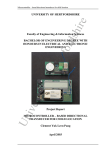
The following application note shows how to connect to a T6963C (as used on the Hitachi
LMG738X,LMG742Xetc..) and provides high level C routines such as plot and print to produce text and
graphics on screen simultaneously. The above display panels also include 8K bytes (0x1FFF) of SRAM which
provides the user with a complete graphics subsystem. The interface between the host processor and the
T6963C is PORT BASED which means the code is easily portable between microcontrollers. The code was
developed and tested using a 16Mhz H8-3334Y. This application note is intended to be used in conjunction
with the T6963C datasheet and the Hitachi LCD Graphics databook.
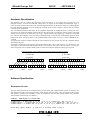
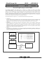
The code described here is split into 3 ‘C’ files which divides the functions up as follows:1. LOWLEV.C
This file contains the basic command write, status check and data read and write cycles as described in the
T6963C. The functions toggle the port lines to re-create the timing diagrams required by the T6963C. It is
designed to act as the bottom layer of the software dealing with the physical levels on the port lines.
2. T6963C.C
All of the high level routines that perform the useful graphics functions such as PRINTF, CLRLCD and
display initialisation are contained in this file. This file does not contain any functions that directly
manipulate the ports. Instead it calls the LOWLEV.C functions to talk to the T6963C. The functions
contained in this file are the ones that should be called from your own code. Any further routines written
by the user (eg. CIRCLE) should be added to this file.
3. MAIN.C
This program is a simple demo to show the use of a couple of the functions provided in T6963C.C. It
initialises the display to Mixed Text and Graphics mode, clears the screen, prints some text and then
bounces a ball shaped sprite around the screen.
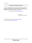
MAIN.C
T6963C.C
DB0-DB7 ------------> I/O port 6 bit 0-7
C/D ------------> OUTPUT from 9.0
WR ------------> OUTPUT from 9.1
RD
------------> OUTPUT from 9.2
REV ------------> OUTPUT from 4.0
CS
------------> OUTPUT from 4.1
F/S
------------> OUTPUT from 4.2
LOWLEV.C
LMG7380
H8/3334Y
Data and control lines
1 of 15
Hitachi Europe Ltd.
ISSUE
: APPS/054/1.0
Hardware Specification
The hardware used to produce this application note consisted of a +12V supply for the INVC191 CFL
backlight inverter, -13V for the LCD bias voltage and a 5V supply for the display and EVB3334Y logic. A
power up delay and fast switch off circuit should be implemented for the LCD bias voltage as recommended in
the LCD Graphics databook to avoid damaging the LCD when the bias voltage is present but the T6963C
controller is not operational.
The connection between the H8/3334Y on the evaluation board and the LMG7380 LCD is via the port lines.
All of Port 6 is used as the databus, with a total of 6 other lines used to provide the control signals. The actual
number of lines used can be reduced by not using a separate WR line and supplying it from an inverted RD
line. Also the REV (display invert) line may be hardwired high to provide the standard black pixel on white
background mode. CS (chip select), C/D (command/data) and at least one line to control Read/Write are
essential.
If required font select FS, Display Off and the CFL on/off line on the inverter may also be controlled directly
from additional ports.
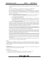
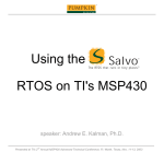
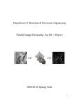
It should be noted that for the graphics routines described in this note to work properly, it is necessary to run
the display in 8x8 font mode (See diagram below). The character font used in the two modes is exactly the
same except that on 8 x 8 mode 2 blank pixels are inserted to bring the character spacing up to 8 pixels.
Diagram showing correspondence between Font Select and graphics display
6 X 8 Font
8 X 8 Font
Screen data
Screen data
X X
7 MSB
X X
Display memory
LSB 0
7 MSB
LSB 0
7 MSB
Display memory
LSB 0
7 MSB
Software Specification
Generation of code
The tools that were used for the code generation are that of the IAR compiler/linker system. As shown in the
first diagram the code is split into three layers which interact with each other. This corresponds to three source
files T6963.C, LOWLEV.C & MAIN.C. These are compiled in turn and then linked together using XLINK.
The batch file used to do this is as follows:COMPILE / LINK Batch file BUILD.BAT
icch83 main.c -o main.r20 -P -g -ml -e -K -C -q -l main.lst -1id -v0 -s0 -r
icch83 lowlev.c -o lowlev.r20 -P -g -ml -e -K -C -q -l lowlev.lst -1id -v0 -s0 -r
icch83 t6963.c -o t6963c.r20 -P -g -ml -e -K -C -q -l t6963c.lst -1id -v0 -s0 -r
xlink main lowlev t6963c
-f link.xcl -l out.map -xsme -o out -r
2 of 15
LSB 0
Hitachi Europe Ltd.
ISSUE
: APPS/054/1.0
rem produce debug .d20 file with source info
The above batch file produces a .D20 file (UBROF format) used by IAR C-Spy and Hitachi CIDE windows
based debuggers for the 300 series. Removing the -r switch from the link command line will cause a S-record
to be produced which is suitable for blowing a PROM.
The link file used to build the code was set up for the EVB3334Y evaluation board which uses the H8/3334Y
16Mhz 8 bit microcontroller.
The link file is shown below:-!
-link.xcl-
First define CPU
-cH8300
-!
-! Allocate segments which should be loaded -!
-Z(BIT)BITVARS=0
-! First allocate the read only segments . -!
-Z(CODE)INTVEC,IFLIST,FLIST=0-FF
-Z(CODE)CDATA0,CDATA1,RCODE,CODE,CDATA2,CDATA3,ZVECT,CONST,CSTR,CCSTR=100-3fff
-!
Then the writeable segments which must be mapped to a RAM area
C000 was here supposed to be start of RAM -!
Z(DATA)DATA1,IDATA1,UDATA1,DATA2,DATA3,IDATA2,IDATA3,UDATA2,UDATA3,ECSTR,WCSTR,TE
MP,CSTACK+140=fb80-ff40
-Z(DATA)DATA0,IDATA0,UDATA0,SHORTAD=Ff41-Ff7F
-! See configuration section concerning printf/sprintf -!
-e_medium_write=_formatted_write
-! See configuration section concerning scanf/sscanf -!
-e_medium_read=_formatted_read
-! Now load the 'C' library -!
clh83sf0
Software functionality
1. LOWLEV.C
• short_delay - provides a small delay (a few tens of machine cycles) to slow LCD access cycles
down
• status_read - performs a read of the t6963c status register and returns it to the calling function
• status_checkx - calls the status_read function to check the presence of a 1 in specific bits of the
status register STA
• command_write - send a command instruction to the t6963c. The command value is passed to the
function as an unsigned char. Available commands are defined in the file command.h
• data_write - used to send data to a display memory location. Note it is necessary to issue a data
write command before this is used.
• data_read - same as above except used to fetch data from the display memory location.
When customising this file for your host processor please note the interface timing specification of the LCD
display as specified in the LCD Graphics Databook.
2. T6963C.C
Note all of the functions here when called first check the appropriate busy flags in the STA register before
attempting to read or write commands or data.
• addr_set - this function sets the address pointer in the t6963c. It should be set before reading or
writing to the display memory unless the value of the pointer is known. By adding the offset of the
3 of 15
Hitachi Europe Ltd.
ISSUE
: APPS/054/1.0
graphics start address for example, it is possible to easily select a specific set of pixels on the
screen. When addressing the character memory a specific character on the screen can be accessed
as follows:-
•
•
•
•
•
•
Character to be addressed = X,Y with the origin (0,0) being the top left hand corner,
use... addr_set( character memory address start + (Y * number of columns) + X);
plot - This function uses the bit set function of the t6963c to manipulate a single bit of graphics
memory. You should pass three unsigned characters to it, the first being the x co-ordinate in
pixels, the second being the y co-ordinate and the third being 1 or 0 depending on whether you
want to set or reset that pixel.
sprite - 8 x 8 sprites can be displayed on the screen using this function and can be placed to pixel
resolution. The parameters to passed to this function are:• 1 - the address of the 8 byte array containing the sprite information (unsigned char *)
• 2 - the x position of the sprite in pixels
• 3 - the y position of the sprite in pixels
• 4 - The writing method used. 0 will AND with existing display data, 1 will OR with the
existing display data and 2 will perform an EXOR. 2 is particularly useful for sprites as
calling the function twice will first display the sprite and then remove it leaving the
screen with the original display data.
lcd_putchr - this function should be used following an addr_set command to tell the t6963c
whereabouts in character memory a character should be placed. The functioned calling lcd_putchr
should pass the character to be displayed and a null. An ASCII translation is performed to allow
normal use of this function. See t6963c user manual for the character set. The address pointer is
incremented after lcd_putchr to allow continuous characters to be sent
lcd_printf - This function uses the IAR formatting library to provide a standard printf function. It
calls lcd_putchr to display the characters after they have been formatted. Use this function exactly
the same way as you would use printf whilst bearing in mind the restrictions on formatters used
according to which write library is specified in the link file. (formatted write)
clr_lcd - This function provides a block erase function on the display memory. Simply pass two
integer values to this function specifying the start and end address of the block to be erased and all
values in that range will be set to 0x00. The Auto write mode is used for speed, where the t6963c
address pointer is automatically incremented after each write.
set_up_lcd - The address map used by the t6963c is set up here which specifies the location of text
and graphics memory within the 8K available. Other parameters such as number of columns,
offset register value (start of custom character memory) are also set up here. Note that the actual
values written depend on the pre-processor defines specified in LMG7380.H. When using different
size displays it is necessary only to adjust the values in this include file as the other files take their
values form here.
This function also selects EXOR mode (text and graphics information will be exored on screen)
and puts the t6963c into mixed text and graphics mode.
3. MAIN.C
This program is a simple demo to show the use of a couple of the functions provided in T6963C.C. It
initialises the display to Mixed Text and Graphics mode, clears the screen, prints some text and displays a
wall around the border, then bounces a ball shaped sprite around the screen. It shows how the functions in
t6963.c are called.
4. COMMAND.H
All of the commands available with the t6963c are defined in this file. It has the benefit of making code
which writes commands to the LCD much more readable.
5. LMG7380.H
This include file has two purposes:1. It defines the constants of the display such as size and start address of memory areas.
2. It declares function prototypes for the functions used in the three c source files
4 of 15
Hitachi Europe Ltd.
ISSUE
: APPS/054/1.0
LOWLEV.C
/*low level routines used to read and write
data and functions to T6963. Includes wait
and staus check routines. The functions are designed
to acurately reflect the timing diagrams given in the
t6963 datasheet
*/
/* the lcd interface is configured as below :DB0-DB7 ------------> I/O port 6 bit 0-7
C/D
------------> OUTPUT from 9.0
WR
------------> OUTPUT from 9.1
RD
------------> OUTPUT from 9.2
REV
------------> OUTPUT from 4.0
CS
------------> OUTPUT from 4.1
F/S
------------> OUTPUT from 4.2
port 6 is initialsied as inputs and port 9.0-2 4.0,2 as outputs
*/
#include
#include
#include
#include
#include
#include
<ioh8337.h> /*io port & peripheral definitions*/
<inh8337.h> /*interrupt vectors*/
<inh83.h>
/*interrupt functions*/
<stdlib.h>
"command.h" /*t6963 commands*/
"lmg7380.h" /*function prototypes*/
void short_delay (void)
{
char count;
count = 3;
while (--count); /* delay */
}
char status_read (void)
{
char read_val;
P6DDR=0x00;
P9DR=0x03;
short_delay();
read_val = P6DR;
P9DR=0x07;
return (read_val);
}
/* port 6 all inputs */
/* set wr/cd clear rd */
/* get status */
/* set rd/wr and cd */
void status_check ( void )
{
while ( (status_read() & 0x03) != 0x03 ) /* wait for status check STA0,1 = 3 */
{ }
}
void status_check1 ( void )
{
while ( (status_read() & 0x03) != 0x03 ) /* wait for status check STA0,2 = 5 */
{ }
}
void status_check2 ( void )
{
while ( (status_read() & 0x08) != 0x08 ) /* check auto write mode STA2,3 = 8 */
{ }
}
6 of 15
Hitachi Europe Ltd.
ISSUE
void command_write (char write_val)
{
P6DDR=0xff;
P6DR=write_val;
P9DR=0x07;
short_delay();
P9DR=0x05;
short_delay();
P9DR=0x07;
short_delay();
P9DR=0x06;
}
/* port 6 all outputs */
/* output the data */
/* output r/w and rs signals */
/* output E signal */
/* output E signal */
/* output rs and r/w signals */
void data_write (char write_val)
{
P6DDR=0xff;
P6DR=write_val;
P9DR=0x06;
short_delay();
P9DR=0x04;
short_delay();
P9DR=0x06;
short_delay();
P9DR=0x07;
}
/* port 6 all outputs */
/* output the data */
/* output control signals */
/* output control signal */
/* output control signal */
/* output control signal */
char data_read (void)
{
char read_val;
P6DDR=0x00;
P9DR=0x06;
short_delay();
P9DR=0x02;
short_delay ();
read_val=P6DR;
P9DR=0x06;
short_delay();
P9DR=0x07;
return (read_val);
}
/* port A all inputs */
/* output control signals */
/* set wr, clear cd/rd */
/* get data */
/* set rd/wr clear cd */
/* set rd/wr and cd */
7 of 15
: APPS/054/1.0
Hitachi Europe Ltd.
ISSUE
: APPS/054/1.0
T6963C.C
/******************************************************************************/
/*This module contains the two essential graphics operations, sprite and plot*/
/*Plot will set a pixel to 1 or 0. Sprite will display a 8x8 pixel sprite
*/
/*anywhere on the screen to pixel resolution (unlike using custom characters) */
/******************************************************************************/
#include
#include
#include
#include
#include
#include
#include
<ioh8337.h>
<inh8337.h>
<inh83.h>
<stdio.h>
<icclbutl.h>
"command.h"
"lmg7380.h"
void addr_set(int address)
{
status_check1();
data_write (address%0x100);
/* low order address */
status_check1();
data_write (address/0x100);
/* high order address ie. graphics!!!*/
status_check1();
command_write (APS);
/* address pointer set */
status_check1();
}
void plot(char x,char y,char val)
{
int addr;
/*address offset from start of graphics*/
addr = ((columns) * y) + (x/8); /*calculate addr offset*/
addr += graph;
/*add on graphics start addr*/
status_check1();
data_write (addr%0x100);
/* low order address */
status_check1();
data_write (addr/0x100);
/* high order address ie. graphics!!!*/
status_check1();
command_write (APS);
/* address pointer set */
status_check1 ();
if (val) command_write (BS + (7-(x%8)));
/*bit set mode*/
else
command_write (BR + (7-(x%8))); /*bit reset mode*/
status_check1 ();
}
void sprite(char *address,char x,char y,char val)
{
int addr;
/*address offset from start of graphics*/
char a,b,temp,shift,sdata;
addr = graph+((columns) * y) + (x/8); /*calculate initial addr offset*/
shift=(x%8);
for (b=0;b<2;b++)
{
for (a=0;a<8;a++)
{
temp = ((char)*address);
address++;
if (b==0) temp = (temp >> shift);
else
temp = (temp << shift);
addr_set(addr);
command_write(DRAAN); /*read data from memory*/
status_check1();
sdata=data_read();
status_check1();
switch(val)
{
case 2: data_write(temp^sdata); /*EXOR with existing data to invert
pixels*/
8 of 15
Hitachi Europe Ltd.
ISSUE
case 1: data_write(temp|sdata);
: APPS/054/1.0
/*OR with existing data to add
pixels*/
case 0: data_write(temp&(!sdata));/*AND with NOT value to take away
pixels*/
}
status_check1();
command_write(DWAAN); /*data write with no addr pointer change*/
addr += columns; /*move down one graphics line*/
}
addr-=(columns*8);
address-=8;
addr++;
shift=(8-(x%8));
}
}
void lcd_putchr(char data, void *ptr)
{
status_check1();
command_write (DAWS);
/* auto data write set */
status_check2 ();
data_write(data-0x20); /*print the character*/
status_check2();
/*need to subtract 20 hex to translate from ASCII*/
command_write (0xb2); /* auto reset */
status_check2();
}
int lcd_printf (const char *fmt, ...)
{
va_list ap;
int i;
va_start(ap,fmt);
i = _formatted_write(fmt, lcd_putchr, (void*)0, ap);
return(i);
}
void clr_lcd (int start,int finish)
{
int n;
addr_set(start);
command_write (DAWS); /* auto write mode set */
status_check2();
n=0;
while (n <= finish)
{
status_check2();
data_write (0x00);
n++;
}
status_check2();
command_write(AR);
status_check2();
}
void set_up_lcd ( void )
{
/*write_lcd control and data codes for character mode*/
status_check ();
data_write (text%0x100);
/* low order addr */
status_check ();
data_write (text/0x100);
/* high order addr */
status_check ();
command_write (THAS);
/* text home address */
status_check ();
data_write (graph%0x100);
/* low order addr */
status_check ();
data_write (graph/0x100);
/* high order addr */
status_check ();
9 of 15
Hitachi Europe Ltd.
ISSUE
: APPS/054/1.0
command_write (GHAS);
/* graphics home address */
status_check ();
data_write (columns);
/* low order addr */
status_check ();
data_write (0x00);
/* high order addr */
status_check ();
command_write (TAS);
/* text area set ,set columns*/
status_check ();
data_write (columns);
/* low order addr */
status_check ();
data_write (0x00);
/* high order addr */
status_check ();
command_write (GAS);
/* graphic area set ,set columns*/
status_check ();
data_write (0x01);
/* low order addr */
status_check ();
data_write (0x00);
/* high order add */
status_check ();
command_write (ORS);
/* 0800H ~ 0FFFH offset register set */
status_check ();
command_write (EM);
/*exor mode */
status_check1();
command_write (TONGON);
/* display mode text on graphics on */
status_check ();
}
10 of 15
Hitachi Europe Ltd.
ISSUE
: APPS/054/1.0
MAIN.C
/********************************************************************/
/* This program is designed to drive the LMG7380 graphics display which
has the Toshiba T6963C controller built-in. This LCM is driven via an
H8 microcontroller on an EVB3334Y. It drives the display in mixed text
and graphics mode. The port lines of the H8/3334Y are used as control*/
/********************************************************************/
#include
#include
#include
#include
#include
#include
<ioh8337.h>
<inh8337.h>
<inh83.h>
<stdlib.h>
"command.h"
/*file with T6963 command codes*/
"lmg7380.h"
/*contains function prototypes and
screen parameters (eg. mem map, columns etc)*/
/*************The following parameters are used for collision
detection***********/
#define wall_l 8
/*horizontal position of LHS of wall*/
#define wall_r 248
/*horizontal position of RHS of wall*/
#define wall_t 8
/*vertical position of TOP of wall*/
#define wall_b 56
/*horizontal position of BOTTOM of wall*/
/**********************define sprites******************************************/
const char ball []= {0x3c,0x7e,0xdb,0xff,0xff,0xdb,0x66,0x3c};
const char brick []= {0xff,0x81,0xbd,0xbd,0xbd,0xbd,0x81,0xff};
/********************************************************************************
/
extern void init_3334y(void);
char collision_det(char,char);
/********************************************************************************
/
void main(void)
{
char ballx,oldx,bally,oldy; /*ball position variables*/
signed char spx,spy;
/*horiz and vert. speed of ball*/
char n,m,*util;
/*general purpose variables and pointer
for passing to sprite function
*/
int count;
/*general purpose counter*/
init_3334y();
/*sets up ports 1,2,4,6,9*/
P4DR=0x01;
/*Chip select Low, enable display access*/
set_up_lcd ();
/*set address of text and graphics,exor mode, display
on*/
clr_lcd(text,text+0x0150);
clr_lcd(graph,graph+0x0b00);
/* clear text display RAM area */
/* clear graphic display RAM area */
addr_set(columns*1);
/*row 1*/
lcd_printf(" The ");
addr_set(columns*2);
/*row 2*/
lcd_printf("Lmg7380");
addr_set(columns*3);
/*row 3*/
lcd_printf(" from " );
addr_set(columns*4);
/*row 4*/
lcd_printf ("Hitachi");
addr_set(columns*7);
/*row 7*/
lcd_printf ("Mixed text and graphics!");
for(n=0;n<58;n++)
{
for(m=8;m<40;m++)
{
plot(n,m,1);
/*black box over text*/
11 of 15
Hitachi Europe Ltd.
ISSUE
: APPS/054/1.0
}
}
util= &brick[0];
/*select brick as sprite to display*/
/*draw top and bottom of wall border*/
for(n=0;n<32;n++)
/*left to right end of columns*/
{
sprite (util,(wall_l + (n*8)),0,1);
sprite (util,(wall_l + (n*8)),56,1);
}
/*draw left and right hand side of wall border*/
for(n=0;n<5;n++)
/*top to bottom of screen*/
{
sprite (util,0,(n*8),2);
sprite (util,56,(n*8),2);
}
/*Game variable initialisation +draw initial bat and ball*/
spx=2,spy=2;
/*initial speed of ball*/
util= &ball[0];
/*select ball as sprite to display*/
sprite(util,oldx,oldy,0);/*draw initial ball*/
while(1)/*MAIN LOOP*/
{
for(count=0;count<0xfffe;count++); /*delay*/
{
util= &ball[0];
/*select ball as sprite*/
sprite(util,ballx,bally,2);/*paint new*/
sprite(util,oldx,oldy,2);/*remove old*/
ballx+=spx;
/*move ball position*/
bally+=spy;
/*collision detection!!*/
if (bally>wall_b)
{
spy=-spy; /*bottom bounce*/
bally=wall_b;
}
if (bally<=wall_t)
{
spy=-spy;/*top bounce*/
bally=wall_t;
}
if (ballx>wall_r)
{
spx=-spx; /*righthand bounce*/
ballx=wall_r;
}
if (bally<=wall_l)
{
spx=-spx;/*lefthand bounce*/
ballx=wall_l;
}
}
}
}
/*******************************************************************************/
/********************************************************************************
/
/*EVB3334Y hardware setup function*/
12 of 15
Hitachi Europe Ltd.
ISSUE
: APPS/054/1.0
void init_3334y(void)
{
P4DR = 0x07;
P4DDR = 0x07;
/*set port 4 to 0x07*/
/* Port 4.0 , 4.1, 4.2 set to outputs */
P9DR = 0x07;
P9DDR = 0x07;
/*set port 9 to 0x00*/
/* Port 9.0 , 9.1, 9.2 set to outputs */
P6DR = 0x00;
P6DDR = 0xff;
P6DR = 0x00;
/*set port 6 to 0x00*/
/* Port 6 set to outputs */
}
13 of 15
Hitachi Europe Ltd.
ISSUE
: APPS/054/1.0
COMMAND.H
/********************************************************************/
/* This file contains definitions for all of the commands in a t6963. */
/********************************************************************/
/* Register set
*/
#define
CPS
0x21
//Cursor pointer set
#define
ORS
0x22
//Offset register set
#define
APS
0x24
//Address pointer set
#define
#define
#define
#define
THAS
TAS
GHAS
GAS
0x40
0x41
0x42
0x43
//Text home address set
//Text area set
//Graphic home address set
//Graphic area set
#define
#define
#define
#define
OM
EM
AM
TAM
0x80
0x81
0x83
0x84
//OR mode
//EXOR mode
//AND mode
//TEXT ATTRIBUTE mode
#define
#define
#define
#define
#define
#define
DOF
CONBOF
CONBON
TONGOF
TOFGON
TONGON
0x90
0x92
0x93
0x94
0x98
0x9C
//Display OFF
//Cursor ON, Blink OFF
//Cursor ON, Blink ON
//Text ON, Graphic OFF
//Text OFF, Graphic ON
//Text ON, Graphic ON
#define
#define
#define
#define
#define
#define
#define
#define
LC1
LC2
LC3
LC4
LC5
LC6
LC7
LC8
0xA0
0xA1
0xA2
0xA3
0xA4
0xA5
0xA6
0xA7
//1
//2
//3
//4
//5
//6
//7
//8
#define
#define
#define
DAWS
DARS
AR
0xB0
0xB1
0xB2
//Data auto write set
//Data auto read set
//Auto reset
#define
#define
#define
#define
#define
#define
DWAAI
DRAAI
DWAAD
DRAAD
DWAAN
DRAAN
0xC0
0xC1
0xC2
0xC3
0xC4
0xC5
//Data
//Data
//Data
//Data
//Data
//Data
#define
SP
0xE0
//Screen PEEK
#define
SC
0xE8
//Screen COPY
#define
#define
BR
BS
0xF0
//Bit RESET
0xF8
//Bit SET
//add 3 bit data to these
//commands to select bit
Line
Line
Line
Line
Line
Line
Line
Line
cursor
cursor
cursor
cursor
cursor
cursor
cursor
cursor
write and ADP increment
read and ADP increment
write and ADP decrement
read and ADP decrement
write and ADP nonvariable
read and ADP nonvariable
14 of 15
Hitachi Europe Ltd.
ISSUE
: APPS/054/1.0
LMG7380.H
#include <inh8337.h>
#include <ioh8337.h>
#include <inh83.h>
/*set up display parameters*/
#define columns 32
#define text 0x0000 /*select text mem start*/
#define graph 0x1000/*select graphics mem start*/
#define font_s 0x08
/********************************************************************************
*/
/*function prototypes for writing to display*/
extern void set_up_lcd(void);
extern
extern
extern
extern
extern
extern
extern
extern
extern
void
void
char
void
void
void
char
void
void
status_check1(void);
status_check2(void);
status_read (void);
status_check ( void );
short_delay (void);
data_write ( char );
data_read ( void );
command_write ( char );
addr_set(int);
extern void lcd_putchr(char, void *);
extern int lcd_printf(const char *, ...);
extern void sprite(char *,char,char,char);
extern void plot(char,char,char);
When using this document, keep the following in mind,
1, This document may, wholly or partially, be subject to change without notice.
2, All rights are reserved: No one is permitted to reproduce or duplicate, in any form, the whole or part of this document without Hitachi’s permission.
3, Hitachi will not be held responsible for any damage to the user that may result from accidents or any other reasons during the operation of the user’s unit according to this
document.
4, Circuitry and other examples described herein are meant only to indicate the characteristics and performance of Hitachi’s semiconductor products. Hitachi assumes no
responsibility for any intellectual property claims or other problems that may result from applications based on the examples therein.
5, No license is granted by implication or otherwise under any patents or other rights of any third party or Hitachi, Ltd.
6, MEDICAL APPLICATIONS: Hitachi’s products are not authorised for use in MEDICAL APPLICATIONS without the written consent of the appropriate officer of Hitachi’s
sales company. Such use includes, but is not limited to, use in life support systems. Buyers of Hitachi’s products are requested to notify the relevant sales office when planning to
use the products in MEDICAL APPLICATIONS.
Copyright Hitachi, Ltd.,1995. All rights reserved
15 of 15