1
®
Badger Meter Europa GmbH
MDS 2000 Oil management
system
USER MANUAL
Version MDS-05/01-e
Contents
Contents
Page
1.
Safety instructions
1
2.
Introduction
2
2
4
4
4
2.1
2.2
2.3
2.4
3.
Software menu
3.1
3.2
3.3
3.4
4.
Description
Memory protected
Reports
Technical data
User menu
Supervisor menu
Customer menu
System menu
Troubleshooting guide
4.1
4.2
Explanations for the transaction end codes
printed on each transaction ticket
Procedure to change the battery
5
5
7
12
19
27
27
27
Important safety instructions
1.
Page 1/27
Important safety instructions
1.
Before installing or using this product, please read the instruction
manual thoroughly.
2. Unpacking: Please check that the product is complete and free from
any damage (check with the further packing list).
3. Only qualified individual should install and/or repair this product.
4. Unplug the MDS 2000 from the electrical outlet before you clean it.
Use a clamp cloth for cleaning and do not use liquid or aerosol
cleaners.
5. Do not place the MDS 2000 on an unstable surface that may allow the
unit to fall.
6. Never place the MDS 2000 near or over a radiator or heat register.
7. Use the type of power source indicated on the label (AC power). If you
are not sure of the type of power available, consult your supplier or
local electric company.
8. The MDS 2000 must be equipped with a plug having a third
(grounding) pin, which fits only into a grounding-type outlet. This is a
safety feature. The MDS 2000 should not be used without a properly
grounded outlet. Failure to properly ground the MDS 2000 may cause
damage to the unit or the data stored.
9. Do not put the MDS 2000 where the cord will be walked on.
10. An extension cord is not recommended for use with the MDS 2000. If
you use an extension cord, make sure that the total of the ampere
ratings on the products plugged into the extension cord does not
exceed the extension cord's ampere rating. Also, make sure that the
total of all products plugged into the wall outlet does not exceed 15
amperes.
11. Unplug the MDS 2000 from the wall outlet and have it repaired by a
qualified service person under the following conditions:
a) When the power cord or plug is damaged or frayed.
b) If liquid has been spilled into it.
c) If it has been exposed to rain or water.
d) If it does not operate normally when the operating instructions
are followed. Adjust only those controls that are covered by the
operating instructions since improper adjustment of other
controls may result in damage and loss of data.
e) If it has been dropped or damaged.
f) If it exhibits a distinct change in performance, indicating a need
for service.
User manual • Version MDS-05/01-e
Introduction
Page 2/27
Warning
Failure to adhere to these safety instructions may result in serious bodily
injury.
2.
Introduction
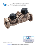
2.1
Description
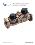
The MDS 2000 is a modular fluid management/security system for
service workshops. It provides the shop supervisor with a host of
services required for precise management of an inventory of
products such as oil, antifreeze, lube, water and gasoline. The
MDS 2000 maintains the inventory by controlling access to hoses,
precise metering of the products, and accurate accounting. A
printed transaction ticket is made upon completion of all
transactions and an inventory report showing all product levels is
available to the supervisor. The MDS 2000 will keep up to 1900
transactions in its protected memory. A transaction historic report
keeps track of all the transactions, classified by user, product or
hose for a convivial research.
The modularity of the MDS 2000 makes it adaptable to your
existing workshop and upgradable to your future, it is comprised of
1 to 8 I/O modules, 1 to 64 data entry keypads, 1 to 16 optional
remote displays and 1 optional PC interface card. The function of
the different system components is:
The I/O module is the operating intelligence. Each I/O module
supports up to 8 counter inputs and controls up to 8 solenoid
drivers – this means that the MDS 2000 can operate up to 64 hose
reels all simultaneously. One I/O module can dialog with 1 to 8
data entry keypads. Each I/O module also supports one additional
input for controlling a waste oil high level switch and one
additional input for activating or deactivating the main air supply.
The data entry keypad will perform the important function of the
system access to the oil monitoring and dispensing procedures for
the garage mechanic. Configuration of the system is also done
from the keypad (for installations without PC). The keypads are all
alphanumerical and equipped with a serial port or to provide
connection to a serial printer. An optional optical pen is available
for bar code reading.
User manual • Version MDS-05/01-e
Introduction
Page 3/27
The remote display is assisting the mechanic. With large 56 mm
digits, it assists the mechanic to visualize the quantity currently
dispensed.
The PC interface card is available as an option and offers extended
remote transaction memory, host computer interfacing and the
possibility to control up to 24 I/O units – which means 192 outlets.
A complete management software package is supplied with the PC
interface card. The software is working under Windows and does
not require a dedicated PC.
To initiate a transaction, the technician enters a personal
identification number (PIN) via the data entry keypad. Any keypad
can dialog with any I/O module. The technician also must enter a
job number, a hose number, and optionally, and odometer reading,
a license plate, and the preset amount. The technician then begins
dispensing the product. The amount of product dispensed thus far
is displayed on the remote display. When the preset amount is
reached, the valve is turned off, terminating the transaction. When
a transaction ends, a transaction ticket is printed on the printer,
and the appropriate inventory is reduced by the amount dispensed.
Should the site be equipped with the optional interface card, the
transaction is sent to the PC. Transactions will also end whenever
dispensing stops for a certain time period.
The transaction ticket contains all data relevant to the transaction
including the job number, the product name, the amount
dispensed, the mechanic's name, the hose used, the type of
transaction, the time and date, the remaining inventory of the
dispensed product and optionally, the odometer reading and
license plate.
The MDS 2000 controls up to 64 hoses and can maintain an
inventory of up to 8 tanks. The system can be configured for use
with pulsers that are single channel or quadrature (w&m approved)
and with variable ratio settings. Access to functions such as
configuration and report printing are restricted to different security
levels; a supervisor code must be entered before these functions
can be used. The supervisor can select the language that will be
used throughout the system.
User manual • Version MDS-05/01-e
Introduction
2.2
Page 4/27
Memory protected
The MDS 2000 unit is provided with sufficient battery backed
RAM to store up to 1900 completed transactions to guard against
data loss in the event of a power failure.
2.3.
Reports
Transaction ticket:
Stock level:
Audit trail of all completed jobs
Stock level of each product tank with minimum
stock level
Product delivery:
Details of all deliveries entered into the system,
date and quantity – and stock corrections
Transaction reports:
Product report – usage and totals
Hose report – usage and totals
User report – usage and totals
All transactions – usages and totals
(Data retrieved from system memory)
Alarm ticket:
If a high level warning switch is fitted to the
waste oil collection tank, a ticket is printed
immediately as a warning
Tank low level warning: When the minimum tank level is reached, a
warning ticket is printed
Job report:
Report review by job number for different grades
against the same job no and from one date to
another (PC level only)
License plate report:
Historic report by license plate no (PC level only)
Configuration:
To keep track of the system configuration for
reconfiguration and after sales services
Note: All the above reports are available to be printed except where
shown as PC level only. When a PC is incorporated all reports can
be viewed on screen before printing.
2.4
Technical data
Network specifications
The MDS 2000 operates with a only TWO WIRES + shield CAN
Bus network communication.
User manual • Version MDS-05/01-e
Introduction
Page 5/27
System specifications
Keypads on a system
I/O modules on a system
Solenoid valves on a system
Meters with single channel pulse transmitters
Fluids on a system
Number of operators
Transaction log
Simultaneous dispenses
Printers per system
64 maximum
8 maximum
64 maximum
64 maximum
8 maximum
99 maximum
1900 maximum
64 maximum
64 maximum
Power supply
The MDS 2000 operates on a 24 V DC voltage.
A power supply unit is included in the system – Voltage input 90 –
120 Volts AC, 50/60 Hz, single phase or 210 – 240 Volts AC, 50/60
Hz, single phase.
3.
Software menu
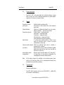
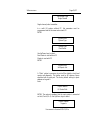
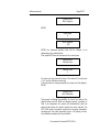
3.1
User menu
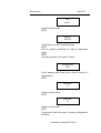
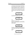
The user menu is accessible through all the keypads. Only the
personal PIN code gives access to this menu.
Enter Pin No.
****
Good morning
(User's name)
Enter Job No.
____________
User manual • Version MDS-05/01-e
Software menu
Page 6/27
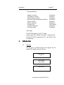
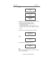
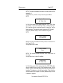
Please introduce the number of the job, ENTER
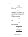
Enter Reg No.
___________
(Optional)
Introduce the vehicle plate number (Alphanumerical), ENTER
Enter Reg No.
___________
(Optional)
Introduce the vehicle mileage, ENTER
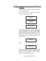
Enter Hose
_0
Introduce the hose's number which corresponds to your request,
ENTER
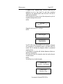
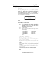
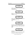
Product
(Product's name)
The system confirms the product's name dispensed on the selected
hose, ENTER
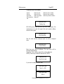
Enter quantity
6.7
(Optional – Dispense mode: Pre-select or free dispense).
Introduce the desired quantity, ENTER
Dispense product
User manual • Version MDS-05/01-e
Software menu
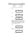
3.2
Page 7/27
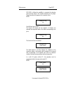
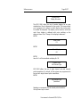
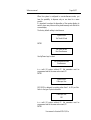
Supervisor menu
The supervisor menu is accessible through all the keypads by
entering the Supervisor PIN Nr.
Every 45 seconds without use of the keypad, the display shows
you the date & time and reset the network.
Enter Pin No.
9999
Good Morning
Supervisor
Supervisor Menu
Start / Stop
The MDS 2000 is equipped with an "emergency" procedure. From
any keypad, press four times the "." key; This will automatically
prevent any oil dispensing. If a solenoid valve (normally closed) is
installed on the main air supply and connected on the I/O unit
(connectors IN8+ ( IN8-), this valve will be shut off by the system.
The selection Start / Stop permits to restart the installation for the
supervisor, ENTER
System State
Active
ENTER
Supervisor Menu
Transaction Report
Upon request, the supervisor can print the transaction's reports.
These reports will give him precise historic of fluids dispensed and
totals. All the reports are printed on the Report Printer as
configurated in the System Configuration Menu.
User manual • Version MDS-05/01-e
Software menu
Page 8/27
Transactions report are available:
By user
By hose
By product
All transactions
Exit
Report by user
Report by hose
Report by product
Report all
(Enter the user's number)
(Enter the hose's number)
(Enter the product's number)
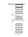
Supervisor Menu
Delivery Rep.
MDS 2000 prints a hard copy of all your stock modifications. We
recommend you to print this report after each product delivery
entered in the system.
Supervisor Menu
Stock Level Rep.
Print the stock and the minimum levels for all the configured
tanks.
Supervisor Menu
Product Deliver
Enter here your new oil deliveries. The new stock will be
calculated automatically.
Suggestion: Print a delivery report after entering deliveries.
Use Up / Down key to select the desired tank, ENTER
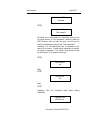
Supervisor Menu
New Stock Level
If you want to modify the stock level:
New Stock Level
Tank 1 = 200
New Stock Level
300 lts
User manual • Version MDS-05/01-e
Software menu
Page 9/27
New Stock Level
300 lts
Supervisor Menu
Set Date / Time
ENTER
Date 18-04-97
Time 15:09
In a multi I/O system, this parameter must be the same on each
I/O.
Every 45 seconds without use of the keypad, the display shows
your the date & time and reset the network.
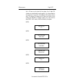
Supervisor Menu
Set super PIN
This prompt is used to change the Supervisor PIN Nr. Only
numerical PIN is accepted by the system. If the supervisor PIN Nr.
has been forgotten, it will be necessary to reset the system and
reconfigure.
ENTER
Supervisor PIN
9999
ENTER
Supervisor Menu
Set super PIN
ENTER
Confirm PIN
****
User manual • Version MDS-05/01-e
Software menu
Page 10/27
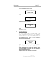
Confirm PIN
Confirmed
ENTER
Supervisor Menu
Clear transacts.
We advise you to clear regularly the transactions when you use
the system without PC: the transactions' numbers is limited to
1900. Moreover, when you print the report, you will have the
printing of all transactions since the last "Clear transactions".
Answering "Yes" will automatically clear all transactions in the
memory of the system. To avoid clearing transactions by mistake,
the system is proposing a "No" answer. Using the down arrow
key will bring the "Yes" answer on the screen.
ENTER
Clear Transacts.
No
Down
ENTER
Are you sure?
No
Down
ENTER
Suggestion: Print your transactions report before clearing
transactions.
Supervisor Menu
Add New User
User manual • Version MDS-05/01-e
Software menu
Page 11/27
Up to 99 users can be stored in the system. Any 4 digits PIN
numbers can be attributed to each operator. It is recommended to
the supervisor to keep a list of the different PIN numbers for the
day it is necessary to remove one of them from access to the
system (see diagnostic in Configure system). Two users with the
same PIN Nr. can't coexist; it will be refused by the systemENTER
New User PIN
****
ENTER
New User Name
(User name)
ENTER
New User Name
User added
Supervisor Menu
Remove User
ENTER
Enter Ex-PIN
****
ENTER
Enter Ex-PIN
User deleted
User manual • Version MDS-05/01-e
Software menu
Page 12/27
The user will be deleted from the system.
Supervisor Menu
Customer Config.
ENTER
Costumer Cfg. PIN
****
Access to the customer security level
Supervisor Menu
Exit
ENTER
Return to User Screen.
3.3
Customer configure menu
The Customer Configure Menu is accessible through all the
keypads. At the initialisation of the system or when modifications
are done on this menu, the datas are automatically updated at the
other keypads through the network. It is not necessary to
configure all the keypads separately.
Customer Menu
Products
All the fluids controlled by the system can be identified in
alphanumerical characters. In certain installations, the same
product can be pumped from different tanks (maximum 8 tanks).
The MDS 2000 allows you to manage these tanks separately to
control their respective stock level.
Assign the tank from which the product will be pumped.
User manual • Version MDS-05/01-e
Software menu
Page 13/27
Enter
Tank N° 1
Introduce the tank number.
ENTER
Product 1
Motor Oil
Use Up/Down key to select the product number.
ENTER
Enter the product's identification by using the alphanumeric
keypad.
ENTER
The system goes back to the prompt "Products"
Customer Menu
Hose
All your dispensing points (hoses) must be linked to the tank it is
dispensing from.
ENTER
Enter Hose
01
Introduce the hose number
ENTER
Enter Tank
01
Introduce the tank number
ENTER
The system will confirm the name of the product configurated for
verification.
User manual • Version MDS-05/01-e
Software menu
Page 14/27
Select Product
Motor Oil
ENTER
Enter Hose "00" to exit
Customer Menu
Warn Level
A minimum stock level must be set for each tank. All fluids
dispenses will automatically be deducted from the respective tank
stock. When the stock level in the tank reaches the minimum level,
a warning reordering message will automatically be printed on the
report printer.
ENTER
Use Up/Down arrow key to select the tank.
Warn Level
Tank 1 = _ _ _ _
ENTER
Warn Level
____0
Introduce the minimum stock level
ENTER
Warn Level
400
Customer Menu
Stop Level
User manual • Version MDS-05/01-e
Software menu
Page 15/27
In addition to the "minimum level", the MDS offers now the
possibility to set up "stop levels" for each tank, preventing
dispenses of the selected product when the level in the tank is
under the stop level limit.
This will prevent air to enter in the oil line and prevent any risk of
impurities entering the line as well.
ENTER
Stop Level
Tank 1 = _ _ _ _ 0
Choose the tank you want to configure
ENTER
New Stop Level
____0
Customer Menu
Dispense Mode
The MDS 2000 offers the possibility for the operator to dispense
oil in pre-select or in free dispense mode. In pre-select mode, the
system will not authorize any dispense without a pre-selected
quantity of fluid.
In free dispense, the system will authorize dispenses without preselection of any quantity.
The system will close the transaction when the inactive time-out
has been reached.
ENTER
Use Up/Down key to select the mode.
Dispense Mode
Pre-Select – Free Dispense
Customer Menu
Odometer & Reg.
User manual • Version MDS-05/01-e
Software menu
Page 16/27
MDS 2000 is offering the possibility to memorize the odometer
and the license plate of the vehicles maintained in the garage.
These information will appear on the transaction ticket;
ENTER
Odometer & Reg.
Yes
Use Up/Down keys to select
The keypad will always ask the operator to introduce the
odometer and registration plate of the vehicle corresponding to the
job nr.
Odometer & Reg.
No
The function will not be activated.
Customer Menu
Initial Timeout
The initial timeout is the time between the validation of the
transaction datas on the keypad and the opening of the solenoid
valve corresponding to the selected hose. Enter the maximum
number of seconds necessary before starting the operation.
In a multi I/O system without PC, this parameter must be
programmed and be the same and on each I/O.
ENTER
Initial Timeout
06
Customer Menu
Inactive Timeout
User manual • Version MDS-05/01-e
Software menu
Page 17/27
The inactive timeout is the period between the last pulse received
by the system and the closing of the solenoid. The MDS 2000 will
close the transaction if the time between 2 pulses reach the
inactive time configurated in the system. It is visualised that the
operator has started to fill the carter with oil and that he has
stopped the dispense before the preset quantity has been reached
or because he is working on a free dispense mode. When choosing
this duration, bear in mind that this should be long enough to
authorise your worker to verify the level on the vehicle stick
gauge.
Inactive Timeout
12
In a multi I/O system without PC, this parameter must be
programmed and be the same and on each I/O.
Customer Menu
Set Language
ENTER
Use Up/Down key to select the language
MDS 2000 is a multi-language system. The default language is
English. To access another language, you will need an area code
provided by the factory.
(UK4164 for English)
Customer Menu
Set Customer PIN
This prompt is used to change the Customer PIN number. Only
numerical PIN is accepted by the system. If the Customer PIN Nr.
has been forgotten, it will be necessary to reset the system and
reconfigure
ENTER
Customer Cfg PIN
****
User manual • Version MDS-05/01-e
Software menu
Page 18/27
ENTER
Confirm PIN
****
Confirm PIN
Confirmed
System Menu
Diagnostics
As a support for the installer and after sales services, MDS 2000 is
provided with an integrated diagnostic enclosing:
- The configuration for the installation parameters
- The names of the products
- The number of the users, their names and their PIN codes
- The hoses, tanks, products' names, displays and correction
factors
We advise you to print this diagnostic after each installation
Customer Menu
Configure System
ENTER
System Cfg. PIN
****
Access to the system configuration installer level.
Customer Menu
Exit
ENTER
Return to the supervisor menu prompt. If you want to come back
at the PIN, press ENTER again.
User manual • Version MDS-05/01-e
Software menu
3.4
Page 19/27
System menu
The System Configuration Menu is accessible through all the
keypads. The modified datas are automatically updated at the
other keypads through the network. It is not necessary to
configure all the keypads separately. Only Tickets (A & B) printers
must be configurated on each keypad.
System Menu
Test Mode
ENTER
Use Up/Down key to select the test.
- Test A:
- Test B:
- Test C:
Test of open/close each solenoid output all the
solenoids one by one, you can hear that the
solenoids are correctly connected
Factory use only.
Test to confirm the address of each large character
remote display.
Display address 0:
Display address 1:
Display address 2:
etc...
Random figures
Figures 000.1
Figures 000.2
- FLT FLT FLT FLT or OK OK OK OK:
This test is only valid for quadrature pulsers.
You have the possibility to test a maximum of 4 quadrature
pulsers connected on the I/O unit.
The position of the message indicates where the position of the
pulser is.
An OK message indicates that the quadrature pulser is well
connected.
A FLT (Faulty) message indicates that the quadrature pulser is
not well connected.
If you connect single pulsers, a FLT message will appear.
- None
User manual • Version MDS-05/01-e
Software menu
Page 20/27
System Menu
Display Allocation
The MDS 2000 offers the use of remote displays for an easy
visualisation of the oil dispensed by the worker. This screen allows
you to program in the system on which display the worker wants
to visualize his dispenses. One display can be used for multi hose
reels. Every display is delivered with micro switches on the
electronic board. See "Change of the displays' addresses".
ENTER
Select Hose
01
ENTER
Select Display
00
ENTER
Hose Nr. 1 will be visualised on display Nr. 00.
System Menu
Set Encoder Type
MDS 2000 allows the use of single channel and dual channels
pulse transmitters. By default, all the systems are programmed to
be used with single channel pulse transmitters.
ENTER
Set Encoder Type
Quadrature
Quadrature corresponds to dual channel pulse transmitter.
Use Up/Down keys to select.
User manual • Version MDS-05/01-e
Software menu
Page 21/27
Set Encoder Type
Single Channel
Single channel pulse transmitter.
In a multi I/O system without PC, this parameter must be
programmed and be the same and on each I/O.
ENTER
System Menu
System Type
System Type
Non-Master
Use Up/Down keys to select.
Non-Master is used without PC.
Master is used with PC.
ENTER
System Menu
Set Report Adr.
A "Main" printer is necessary to print all the statistic, stock level
reports and diagnostic. This printer must be 80 columns, Epson
emulated with a serial port. The factory default setting is report
address on keypad 0.
Enter
Report Address
I/O Control Unit
ENTER: The network considers that the main printer is connected
on the I/O unit (ID=0). Use Up/Down keys to select
Report Address
Keypad x
User manual • Version MDS-05/01-e
Software menu
Page 22/27
ENTER: The network considers that there is no main printer on the
keypad Nr. 0.
Use Up/Down key to select until you have the good address
ENTER
System Menu
Set Ticket A Adr.
To fulfil all the needs of the garage supervisor, MDS 2000 offers
the flexibility to print the transaction tickets on different printers.
All the printers must be connected through the serial port and be
Epson emulated. This instruction must be done on EACH keypad.
The factory default setting is Ticket A address on Keypad 0.
ENTER
Ticket A Address
I/O Control Unit
ENTER: The network considers that the printer is the connected on
the I/O unit (ID=0).
Use Up/Down keys to select
Ticket A Address
None
ENTER: The network considers that there is no ticket printer on
the system.
Use Up/Down keys to select the address
System Menu
Set Ticket B Adr.
To fulfil all the needs of the garage supervisor, MDS 2000 offers
also the flexibility to print a copy of the transaction tickets. All the
printers must be connected through the serial port and be Epson
emulated. This printer can be the main printer. This instruction
must be done on EACH keypad. The factory default setting is ticket
B address on keypad 0.
User manual • Version MDS-05/01-e
Software manual
Page 23/27
Ticket B Address
I/O Control Unit
ENTER: The network considers that the ticket printer is connected
on the I/O unit (ID=0).
Use Up/Down keys to select
Ticket B Address
None
ENTER: The network considers that there is no ticket printer on
the system.
Use Up/Down keys to select
Ticket B Address
Keypad x
ENTER: The network considers that the ticket printer is connected
on the keypad Nr. x.
Use Up/Down keys to select the address
ENTER
System Menu
Set Ticket PIN
The installer PIN code can be modified. Only numerical PIN is
accepted by the system. If the installer PIN Nr. has been
forgotten, it will be necessary to reset the system and reconfigure.
ENTER
System Cfg PIN
****
MDS 2000 operates all the hose reels simultaneously or one hose
reel at a time.
When the system is configured in simultaneous mode, you will be
able to dispense on all the different hoses at the same time.
User manual • Version MDS-05/01-e
Software manual
Page 24/27
When the system is configured in non-simultaneous mode, you
have the possibility to dispense only on one hose for a same
product.
It's important to analyse the disposition of the remote displays to
avoid to have many hoses working simultaneously and affected to
a same display.
The factory default setting is simultaneous.
System Menu
Set Simult. Mode
ENTER
Set Simul. Mode
Non-Simultaneous
Use Up/Down keys to select
Set Simultaneous Mode
Simultaneous
In a multi I/O system without PC, this parameter must be
programmed and be the same and on each I/O.
ENTER
System Menu
Pulses per Litre
MDS 2000 is designed to register pulses from 1 to 255 per liter.
Refer to the type of pulse transmitter.
Pulses per Litre
100
In a multi I/O system without PC, this parameter must be
programmed and be the same and on each I/O.
ENTER
User manual • Version MDS-05/01-e
Software manual
Page 25/27
System Menu
Max. Dispense
ENTER
Select Hose
0
Max. Dispense
_ 100
ENTER the maximum quantity that will be allowed to be
dispensing on the selected hose.
Then press ENTER and do the same for the other hoses.
System Menu
Decimal Place
Decimal Place
1
From here you can choose the place of the decimal. You only have
1 or 2 (use the Up/Down arrow key).
)!You also have to change physically the jumper into the display!).
ENTER
System Menu
Hose Calibration
This prompt is offering the possibility to correct the delay of the
solenoid valve shut-off. When an operator presets a quantity of
fluid to be dispensed, the system will automatically close the
solenoid valve when the preset quantity has been reached. The
MDS 2000 counts the pulses coming from the pulse transmitter.
assuming that the pulse transmitter type is 100 pulses per liter,
the calibration procedure will be as follows:
User manual • Version MDS-05/01-e
Software manual
Page 26/27
Preset quantity:
Quantity dispensed:
Difference:
4 litres = 400 pulses
4,1 lt. = 410 pulses
0,1 lt. = 10 pulses
10 will be the calibration factor to introduce in the system
ENTER
Select Hose
01
ENTER
Pulse count
10
ENTER
System Menu
Change I/O ID
By default all the I/O units have the same address (ID) Nr. 0
corresponding to solenoid drivers (hose reels) 10 to 8. For the
installation with multi I/O units (more than 8 hose reels), each I/O
must have its own address to be identified by the network. Power
up each I/O successively and change their address. For example ID
Nr. 1 for solenoid drivers (hose reels) 9 to 16.
ENTER
Change ID I/O
From 0 to 1
ENTER
The network dialogs now with this I/O unit 1 for hoses 9 to 16.
System Menu
Exit
User manual • Version MDS-05/01-e
Troubleshooting guide
Page 27/27
ENTER
Return to customer configure menu at the exit prompt. To return
to the user screen, press twice ENTER.
4.
Troubleshooting guide
4.1
Explanations for the transaction end codes printed on each
transaction ticket
0 Means that the transaction has been stopped after the inactive timeout:
- It's normal in free dispense mode
- The preset quantity has not been totally dispensed
1 In preselect mode, the preset quantity has been totally dispensed:
Completed
2 Input error in the pulses sequence: For quadrature pulseres only
3 Count error: Missing pulse in quadrature pulsers only
4 It means that the power has been shut down during the transaction:
Power down
5 The transaction has been stopped by the emergency procedure ("..."):
System inactive
6 IOP error: Microprocessor error
7 Unauthorised transaction: For approved systems only, quantity
dispensed between 0,5 Lt and 100 Lt.
4.2
-
Procedure to change the battery
Test of the RAM "MAX690" next to the battery:
With power 24 VDC: Pin 3 (-) Pin 7 (+) = 5 VDC
Without power 24 VDC: Pin 4 (-) Pin 8 (+) = 3 VDC (2 VDC min)
Print a diagnostic and your reports by security.
Under tension, remove the battery and replace it by a new one.
Battery's references: Lithium Manganese Battery
3 VDC – 180 mAH – Type CR2032
Dimensions: L: 2.3mm Diam: 20.0mm
Lifetime: +/- 2 years
User manual • Version MDS-05/01-e
Hotline
Tel.
Fax
®
+49-7025-9208-0 or -29
+49-7025-9208-14
Badger Meter Europa GmbH
Subsidiary of Badger Meter, Inc.
Karlstrasse 11
72660 Beuren (Germany)
E-mail: [email protected]