1
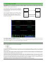
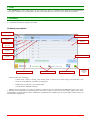
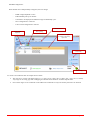
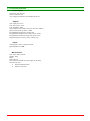
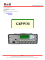
Diefi INSTRUCTIONS MANUAL V0.2 Bat. 20, ZA de La Mare 2 10 Avenue du Fief ZI des Béthunes 95310 SAINT OUEN L’AUMONE FRANCE TEL : 01 30 37 03 82 - FAX : 01 30 37 05 33 Email : [email protected] Site Internet : www.diefi.com G6PWM Diefi Développement en Informatique, Electronique et Fabrication Industrielle S.A.S. au capital de 7 500 € - SIRET 451 878 961 00031 – APE 7112 B – N° T.V.A. FR 09 451 878 961 Instruction for version 1.1 1. Table of contents Table of contents ................................................................................................................................................................. 2 Introduction ......................................................................................................................................................................... 2 Terminology ........................................................................................................................................................................ 2 Power supply ....................................................................................................................................................................... 3 Navigation ........................................................................................................................................................................... 3 Keys ......................................................................................................................................................................................... 3 LEDs........................................................................................................................................................................................ 4 6. Menus .................................................................................................................................................................................. 4 PWM GENERATION (1/6) .................................................................................................................................................... 4 PWM MEASURMENT (2/6) .................................................................................................................................................. 4 PWM FREQUENCIES (3/6) ................................................................................................................................................... 4 PWM VOLTAGE (4/6) ........................................................................................................................................................... 4 PULL-UP ON PWM (5/6)....................................................................................................................................................... 4 SYSTEM INFO (6/6) .............................................................................................................................................................. 4 7. Analog input ........................................................................................................................................................................ 4 8. Connections output .............................................................................................................................................................. 5 Functions ................................................................................................................................................................................. 5 9. Connecting the G6PWM ..................................................................................................................................................... 6 10. Power supply modes ........................................................................................................................................................ 6 11. USB ................................................................................................................................................................................. 7 12. Software ........................................................................................................................................................................... 7 Software presentation .............................................................................................................................................................. 7 13. Technical features .......................................................................................................................................................... 10 Power supply ..................................................................................................................................................................... 10 Outputs .............................................................................................................................................................................. 10 Inputs ................................................................................................................................................................................. 10 14. Maintenance .................................................................................................................................................................. 11 1. 2. 3. 4. 5. 2. Introduction G6PWM (Generator 6 Pulse Wide Modulation channels) is designed to generate and read back control pulse wide modulation signals. This device is especially uses in the automotive industry for controlling pumps and other smart tools. The G6PWM device can be fully controlled and configured by software and is able to drive 6 independent channels. A menu scrolling makes the device easy for configuration on standalone applications. Its small size and strength makes it ideal for use in industrial environments. 3. Terminology PWM: Pulse Wide Modulation. FREQ: Frequency. AC: Alternative current. DC: Direct current. G6PWM Diefi Page 2/11 4. Power supply G6PWM can be powered by an outlet, USB connection, on main AC power outlet or by an external power supply 10-24V. For standalone use, the box has a rechargeable battery with a life up of 10 hours. The battery is charging only when G6PWM is powered by an outlet or by an external power supply. 5. Navigation Keys LCD screen Keypad Battery level Analog input USB input Switch ON/OFF The scrolling menu simplifies setup variables, options and performance features. Function keys: ▼ : Go to the down digit. ▲ : Go to the up digit. ◄ : Go to the left digit. ► : Go to the right digit. ˹·: Go to the previous menu ˻· : Go to the next menu ○ : Select/Unselect digit. When a digit is selected: ▼ : Decrement digit. ▲ : Increment digit. G6PWM Diefi Page 3/11 LEDs Leds indicate battery level or the type of power (USB or external voltage): Type of power: - Top green led is ON: external voltage (12 V or AC outlet) and internal battery fully charged. - Up shifting green leds: external voltage (12 V or AC outlet) with charging internal battery. - Middle green led is ON: USB power Battery level: - 70% - 100% : All leds (green) - 50% - 70% : 2 leds (green) - 10% - 50% : 2 leds (orange) 0% - 10% : 1 led (red) 6. Menus Menu PWM Generation (1/6) PWM Measurement (2/6) PWM Frequencies (3/6) PWM Voltage (4/6) PULL-UP on PWM (5/6) System info (6/6) PWM1 to PWM6 PWM1 to PWM6 FREQ1 to FREQ6 PWM1 to PWM6 Channel1 to Channel6 PWM control On board battery level External voltage 00.0 % to 100% 00.0 % to 100% 1 Hz à 9999 Hz 5V to 20V ON or OFF Digital or analog Typically from 2.5V to 4.2 V 7V to 15V PWM GENERATION (1/6) Adjustment of duty cycle, with duty cycle ranging from 0% to 100% with 0.1% steps. PWM MEASURMENT (2/6) PWM measurement in each channel, with a 0.1% precision. PWM FREQUENCIES (3/6) Frequencies setting, with frequency ranging from 1 to 9999 Hz with 1 Hz steps. PWM VOLTAGE (4/6) PWM amplitude setting, with amplitude ranging from 5V to 20 V with 1V steps. PULL-UP ON PWM (5/6) Pull-up settings, enabling or disabling 2.7KΩ pull-up on PWM Open Collector output. SYSTEM INFO (6/6) Frequencies setting, with frequency ranging from 1 to 9999 Hz with 1 Hz steps. 7. Analog input On the front panel the G6PWM has 6 analog inputs to control the 6 PWMs signals. Each input can be independently control. G6PWM Page 4/11 Diefi Duty cycle can be control by an analog voltage input. The option “Analog” can be activated by changing the PWM control in SYSTEM INFO (6/6). In this mode, the analog voltage input range is 0-10V with 0.1V 1% of PWM accuracy. 8. Connections output External DC power supply (12V) I/O PWM open collector Switch ON/OFF + outlet + fuse PWM programmable voltage output TTL Output Functions G6PWM has 3 kinds of outputs: CAUTION: All ground signal are common (Output, Input, USB and external DC power supply). The G6PWM has six fully independent channels. Each one has three kinds of output: - TTL - PROGRAMMABLE VOLTAGE OUTPUT - OPEN COLLECTOR The TTL output can be used to drive very low power systems. This output is the most accurate of the three. The Programmable Voltage output (Prg V) is a copy of the TTL but gives the user the ability to control the voltage amplitude with the software. The output voltage can be set from 5V to 20V by 1V steps. Internal External The Open Collector output is more complex than the two others. This channel can generate and read back simultaneously. This output is typically an open collector with a 100mA current limitation. This open collector is complemented with a programmable pull-up resistor. The resistor can be either connected to the external DC power supply when available or to the onboard 12V. The read back feature is on this same pin out. This means that the read back function is only available when the open collector is OFF. 12V Supply 2.7KΩ Read Back In/Out 100mA PWM G6PWM Diefi Page 5/11 9. Connecting the G6PWM The G6PWM can be connected using any of the 3 outputs available for each channel. To connect a slave device to the G6PWM the user has to be aware of what the external device requires. There are 2 mains ways of doing so: One Signal Connection and Two Signals Connection. The One Signal Connection uses fully the capabilities of the Open Collector output. The mean the command and the feedback are on the same wire. The connection is as shown beside. G6PWM Device X OC Output OC Output The Two Signal Connection can use either the TTL or the Programmable Voltage output as driver but the read back is only available on the Open Collector signal. CAUTION: The signal sent by the slave device must be an open collector aswell. G6PWM Device X Prog Volt Input OC Output OC Output The signal generated by the G6PWM in this example is 50Hz 40% PWM ratio TTL (in blue) and the read back when the level is high is 1KHz 45% PWM ration (in yellow). This example demonstrates that if the control PWM and the read back PWM frequency has a ratio of less than 50 the result when the control PWM is low (ei 10%) the read back might be compromise. 10. Power supply modes There is a wide range of ways to power up the G6PWM: • Main AC • Main DC • USB • Onboard battery All modes can be use at anytime but user has to be aware of it to prevent depleting the battery by accident. It is recommended to keep the AC on the back ON at all time. The main switch on the front panel turns ON/OFF the power except when the USB is connected. A long as there a power supply available on the back of the device the battery will keep charging even thought the front panel switch is OFF. The switching between AC and DC is automatic. The user does not have to take care of it. If neither power is available the battery will back up the system up to 10 hours. It takes about 24 hours to fully recharge the battery. When it does charge and the front switch is ON, the 3 leds are shifting indicating the charging mode. When using the internal battery the 3 leds will display the battery level as describe previously. When connecting an USB cable with the font panel switch OFF the electronic will power up using the power supplied for the PC. If you do not want to drain down power from the USB (ei: in case of a standalone laptop) you should switch ON the G6PWM first to use the main supply or the internal battery before plugging in the USB. IMPORTANT: When powering the G6PWM from the USB port this does not recharge the battery. G6PWM Diefi Page 6/11 11. USB The G6PWM has on the front panel a B type USB port which is compatible with Windows XP/VISTA/SEVEN environment. USB driver is provided (atmel_devices_cdc.cat and atmel_devices_cdc.inf files) and must be installed. 12. Software The G6PWM application is “G6PWMApplication.exe”. To run this application you must install Microsoft .NET Framework 3.5. minimum. The software package is provided. Software presentation Selection tab Cycle progress bar PWM generate Frequency Measurement indication PWM generate duty cycle PWM duty cycle responce Save new parameters PWM frequency responce Selection control mode Voltages indication Com port selection G6PWM connection state In this window, user can change: - Control mode : digital or analog, when analog mode is selected, user cannot change the PWM duty cycle because it is automatically controlled by analog input. - PWM frequency and duty cycle in digital mode. - Communication G6PWM COM port PWMs frequency and duty cycle return are display according to the user configuration and PWM duty cycle return value. A message can be displayed for indication purpose. The “Save” button will save the current settings. PWM cycles can be programmed to generate different values of PWM for a predefined period. PWM cycle tab is presented as follows when user activate EDIT configuration: G6PWM Diefi Page 7/11 Optional filename Path saving selection Cycle in second Edit/run selection Load a saved cycles Save current cycles Duty cycle value in % SAVING PATH: user must configure a “Saving Path” before starting a cycle and record measurements. SAVE CYCLE: to save the current PWM list cycle in text format. LOAD CYCLE: to load a saved PWM list cycle in text format. After entering data cycle, user can change “Edit” mode to “Run” mode. START button and PAUSE button appear to execute PMW cycle list: Current cycle Start the cycle Cycles progress bar Pause Creating a program is very straightforward. First the time of how long each PWM generation can last (in seconds) has to be set then the PWM values of each channel can filled. G6PWM Diefi Page 8/11 G6PWM configuration: Each channel can be independently configured, user can change: - PWM voltage amplitude: 5-20 V. - Enable/disable pull-up on channel. - Comments to be displayed for different ranges of PWM duty cycle. - Save configuration in a text file. - Load a saved configuration in text file. Channel selection Change PWM amplitude Pull-up setting Comments to displays according to PWM duty cycle value Load config Save config To create a level indicator there are simple rules to follow: • The user has to set the read back ranges (ei: 0→10%, 10.1%→40%, 40.1%→80%, 80.1→95%, 95.1%→100%). Any range can be setup, gaps and overlapping are allowed but the behavior would be unpredictable. • Once all the ranges are set comments can be added. The comments are only texts and any characters are allowed. G6PWM Diefi Page 9/11 13. Technical features Power supply From 8V to 24V DC 5W. 100V to 240VAC 5W. Any voltage beyond those will damage the device. Outputs TTL ouput level: 0-5V. TTL max current: 5mA. TTL impedance: 50Ω. Open Collector max output current on low side: 100mA. Open collector pull up value: 2.7KΩ. Programmable Output max voltage: 20V. Programmable Output max low side current: 30mA. Programmable Output max high side current: 3mA. Output frequency accuracy on any channel: 1µs. Inputs Analog input ±10V 1% fully protected. Input impedance: 10KΩ. Miscellaneous Size: 260 x 200 x 105mm. Weight : 2Kg. IP40. Class I device Switch button ON/OFF for main supply on the back. Protection by fuse • External 500mAT 230V. • Internal 1AT 230V. G6PWM Diefi Page 10/11 14. Maintenance In case of power failure, the device has two fuses: • One in the back for AC protection: 500mAT 230V 6x20mm. • One inside the enclosure for DC protection: 1AT 230V 6x20mm. In order to change the internal fuse the 4 screws on both side of the enclosure have to be removed ant the top to be opened. When changing the fuses the device must be disconnected from any power source. . Remove the 2 top screws on each side Fuse It is recommended to change the battery every two to four year depending of the usage intensity. The G6PWM must be returned to Diefi for this operation. G6PWM Diefi Page 11/11