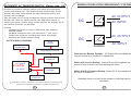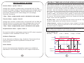
1
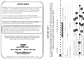
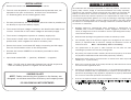
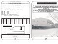
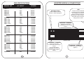
and
WARRANTY REGISTRATION CARD
IRM
SERIES
A
NEW
WORLD
®
INDUSTRIAL RACK MOUNT
Please
Affix
Stamp
Here
[email protected]
[email protected]
email:
email:
LATRONICS
P.O. BOX 73
MOFFAT BEACH QLD 4551
AUSTRALIA
POWER
www.latronics.com
web:
web: www.latronics.com
6988
54916988
61 775491
Ph
Ph 61
Latronics P.O. Box 73 Moffat Beach Qld 4551 AUSTRALIA
INSTRUCTION MANUAL
SINEWAVE INVERTER
It is important to us at Latronics, that our clients enjoy the maximum
benefits from our Inverters, in a safe and productive environment. Thus
we strongly advise that you read through the next few pages of this
manual, which explains all the modes of operation and relevant safety
precautions for your new Power Inverter.
Please remember to complete and return your registration card or
complete the online registration to validate your 3-year warranty.
Please retain your receipt as proof of purchase.
Copyright Latronics.
Doc No A340-D04-V05-Q2 Version 5
Latronics products are all proudly designed, engineered and manufactured
in Australia. As a specialist Sine Wave Inverter company we produce
Inverters for a diverse range of applications such as; mining, railways,
telecommunications, marine, remote power, motor homes, and other
industrial or commercial installations.
In order to produce the most reliable products available, Latronics
Inverters have been designed to endure the most rugged terrain and the
harshest conditions across the Australian continent.
All products are engineered using the latest high quality components and
manufactured to stringent quality standards, thus ensuring Latronics
customers all enjoy many years of trouble free operation.
How do you rate the service from your supplier?
Did your new Inverter meet your expectations?
*
*
* Was your decision made because of?
Features
Value for Money
Appearance
Good
Above Expectations
Fair
Batteries
Yes
Very Good
Warranty
Wind
Commercial
Recommendation
What Energy Source is connected to your Inverter? Solar
*
Residential
Where is your Inverter being used?
*
....................................
Excellent
Australian Made
No
Other
.......................................................................................................................................................................................................
Email / Phone (optional):..................................................................Comments:...........................................................................
Date of Purchase:............................................Supplier:................................................................................................................
Name:....................................................................................Post code:.......................Serial No:.................................................
Your warranty is only valid if this card or online registration is completed within 3 months of the date of purchase.
REGISTRATION CARD
Serial No.................................... Date card returned..............................
As an environmentally conscious customer you may choose to
Register online at http://latronics.com . Once completed online,
there is no need to post this registration card.
11/09
IMPORTANT !
WELCOME
INVERTER EFFICIENCY & OUTPUT WAVEFORM
TABLE OF CONTENTS
PAGE
INSTALLATION
2
BATTERIES
3
DIP SWITCH SETTINGS
4
AUTOMATIC RESET FEATURE
5
AC TRANSFER SWITCH
6
SPECIFICATIONS
8
INVERTER OPERATION
10
SAFETY & AC WIRING
12
INVERTER WIRING & CONNECTIONS
13
MISCELLANEOUS OPTIONS
14
FAULT FINDING
18
WARRANTY CONDITIONS
19
-100
INVERTER EFFICIENCY & OUTPUT WAVEFORM
20
-200
WARRANTY CARD
21
Latronics Inverters Efficiency versus Load
90%
80%
High efficiency even
@ low levels
60%
50%
40%
Efficiency
70%
30%
20%
10%
0%
5%
10%
25%
50%
75%
100%
Load
400
300
AC Voltage
200
100
0
-300
®
-400
A
20
NEW
1
WORLD
POWER
INSTALLATION
WARRANTY CONDITIONS
• Ensure the Inverter has not been damaged in transit.
• The unit must be placed in a well-ventilated and protected area, not
exposed to the open environment, and free from contaminates
(i.e. Exhaust gases, sea air, battery gases, dust).
DC WIRING
• For best performance, the unit should be placed as close as possible, but
not directly on top of the battery supply.
All conditions and warranties expressed or implied by statute, common law,
equity, trade, custom, usage, or otherwise howsoever are hereby expressly
excluded to the maximum extent permitted by law. Where so permitted the
liability of Latronics for a breach of condition or warranty that cannot be
excluded is limited (at Latronics option) to the replacement or repair of the goods
or of acquiring equivalent goods or the cost of replacing or repairing the goods or
of acquiring equivalent goods. Latronics shall not be liable in any way whatsoever
for indirect or consequential loss or damage whatsoever (whether based on tort
or contract or otherwise).
!
Damage caused by unauthorized repair, alteration or substitution of nonstandard parts, incorrect installation, misuse, negligence, accident or similar
cause, or usage other than in accordance with the operating instructions, is not
covered under warranty.
!
Unauthorized opening of the goods will render the warranty invalid.
• The Inverter is fitted with a circuit breaker in line with the battery
positive lead, which negates the need for a battery fuse.
!
• Ensure the Inverter is switched OFF before connecting the DC supply.
Turn the circuit breaker switch to the OFF position.
The company may, at its discretion, agree to act as agent for the owner where
delivery is requested and all costs for cartage and insurance will be for the
owners account.
Note: *All warranty work is ex-factory.
!
The replacement of any part or labor involved will not have the effect of
extending the period of the warranty of the goods.
• Connect the Inverter DIRECTLY to the battery terminals for best
performance.
!
Any faulty part replaced under warranty becomes the property of the Company
for purpose of examination and claim under proprietary warranty.
!
Registration Card must be returned within 3 months from date of purchase to
validate your 3-year warranty.
!
Keep your receipt as proof of purchase, should any difficulties arise concerning
the return of the registration card.
!
Inverters are supplied by the manufacturer, or the manufactures agents, under
the express condition that no responsibility is implied or accepted by the above
parties for any damage to any appliance, equipment or property associated with
the correct or otherwise operation of the Inverter.
!
If service is required contact your local supplier/installer, or contact Latronics
direct. Please ensure that you have the Inverter Model and Serial number
available to enable prompt processing.
• The Inverter DC input voltage is stated on the identification label of the
Inverter. Check that it is the same voltage as the battery supply.
• The Inverter is designed to operate on a battery supply only.
• Input leads marked RED = (positive), & BLACK = (negative).
* Note:- The DC input is electrically isolated from the AC output and
either the battery positive or negative can be earthed.
OBSERVE POLARITY
NOTE: Cables connecting the Inverter to the battery are
designed to achieve maximum efficiency and output power:
DC CABLES SHOULD NOT BE EXTENDED
2
19
FAULT FINDING
Should the Inverter appear to be malfunctioning we suggest the
following to eliminate any external problems:
1.
Turn the Inverter “OFF” via the Circuit Breaker switch on the front
panel.
2.
Disconnect all AC wiring from the Inverter.
3.
Disconnect DC battery leads from Battery. Clean all terminals by
removing all grease/corrosion on both DC leads and battery
terminals.
4.
Ensure you have sufficient battery capacity at the nominal voltage
(specified on the compliance label of your Inverter).
Please note: Use minimum 100AH Battery or the size of
a substantial Car Battery.
5.
Make connection directly to battery terminals and ensure all
connections are tight.
6.
Remove all other wiring from battery to ensure that the Inverter is the
ONLY device connected to the battery bank.
6.
Ensure battery voltage is within the correct limits as outlined in the
section INVERTER SPECIFICATIONS of this manual. If you do not
have a DC voltmeter or multimeter check the front panel for
Overvolts and Undervolts LED’S.
7.
Turn the Inverter ON via the Circuit Breaker switch on the front panel.
Observe the lights on the front left of your Inverter. Refer to
INVERTER OPERATION sections for explanation of Indicator lights.
8.
Plug in various appliances and monitor the Inverters operation.
HELPFUL HINTS
*
Remember that the Inverter automatically starts when a load is
applied.
*
Make sure leads and terminals are not corroded or faulty in any way.
*
Make sure the Inverter goes into STANDBY with no load switched
on.
*
Make sure the Circuit Breaker is reset properly. If unsure switch OFF
and ON again.
18
BATTERIES
BATTERY SIZING
It is important to match your battery size according to the power rating of
the Inverter.
To ensure peak performance, it is important to choose the right battery for
your Inverter. The battery size required will depend on the load and intended
running time. Use this formula as a general guide:
Recommended Battery Size= Inverter rating in watts ÷ input voltage × 10
e.g. 1200W ÷ 12V x 10 = 1000Ah
Minimum Battery Size = Inverter rating in watts ÷ input voltage × 3
e.g. 1200W ÷ 12V x 3 = 300Ah
Do not use an undersized battery as this may result in an Inverter that does
not start or that will rapidly discharge the battery and may cause damage to
the battery.
MAINTENANCE
Battery terminals require frequent care and maintenance. Very high current
(up to several hundred amps), is drawn by the Inverter when starting
electrical motors and other high power appliances. We recommend an
inspection of the batteries and the interconnecting cable connections once
every 1-3 months or as recommended by the battery manufacturer.
1. Regularly check all connections; make sure they are always tight.
Battery terminals are made of soft lead which will slowly compress over
time eventually causing loose connections.
2. Check all connections are free of corrosion. Remove any corrosion and
coat the terminals with Vaseline or grease to help prevent future
corrosion.
3. Take specific gravity or SG readings of each cell using a hydrometer to
check the level and performance of each battery. Alternatively a battery
voltage reading for each cell will suffice, but may not be accurate for
multiple batteries connected in parallel. Report any serious imbalance to
your system installer or battery supplier for corrective action.
SAFETY
When working on batteries protective clothing and eye wear should be
worn. Extreme care should be taken not to short circuit any battery
terminals especially with tools. If in doubt have the work carried out by
qualified personnel.
3
DIP SWITCH SETTINGS
Dip Switch Settings apply to all models from 1000W to 5000W inclusive.
In order to access these options you have to open the Inverter. Before
altering the settings switch Inverter OFF, adjust the setting and switch
Inverter back ON again. We recommend these adjustments be carried out
by qualified personnel or your system installer.
SW1
Hz
50/60 Hz
ON = 50Hz (factory setting)
SW2 SP
SW3 SP
SW4 SP
SW5 & SW6
OFF = 60Hz
Special
Special
Special
UV
Undervoltage Settings
STATEMENT OF QUALITY ASSURANCE
The whole of the supplies have been subjected to the Quality
System Requirements in accordance with the conditions of AS/NZS
ISO 9002: 1994.
All items are manufactured with full traceability.
All IRM Series True Sinewave Inverters conform to the C-Tick mark
for the EMC emission standard EN55014.
SW5 OFF & SW6 OFF= (factory setting)
Setting
SW5
SW6
ON
OFF
ON
OFF
ON
OFF
OFF
ON
12V Value
24V Value
48V Value
Disconnect Reconnect Disconnect Reconnect Disconnect Reconnect
10.0
10.5
11.0
11.5
12.0
12.5
13.0
13.5
20.0
21.0
22.0
23.0
24.0
25.0
26.0
27.0
40.0
42.0
44.0
46.0
48.0
50.0
52.0
54.0
DIP SWITCH LOCATION
1
2
3
4
5
6
MAIN PCB
OFF
ON
DIP Switch located on Main PCB
WARNING:
Due to dangerous voltages existing inside the unit, make sure the circuit breaker switch is turned
off before opening the unit. These adjustments must be performed by a qualified and licensed
personnel only.
4
17
RADIO FREQUENCY INTERFERENCE
Radio Frequency Interference (RFI) is a phenomenon that exists in modern
society and is a problem in many areas of electronics. For Inverter users,
RFI normally presents itself in the form of static and/or interference when
listening to an AM radio and in unusual cases may interfere with TV reception.
Over the years Latronics has continued to invest significant time and effort in
the reduction of RFI related emissions from the entire product range, so that
they comply with the appropriate International and/or Australian Standards.
Even with this compliance, there are situations where RFI may still be a cause
for concern, and can differ greatly from installation to installation. Accordingly,
the following is a list of recommendations made to assist in the overall reduction
of RFI.
1.
Separate DC and AC wiring. Avoid running DC and AC cables in the
same conduits and/or cable trenches. It is strongly recommended that
DC and AC wiring be separated by the greatest distance possible. In
extreme cases, the use of shielded conduit may be necessary.
2.
Minimize length of DC cabling. DC cables can act as an aerial, therefore
all such cables should be kept as short as is practicable. For best
performance minimize DC cable length to Inverter and Batteries and if
possible avoid the use of Auxiliary DC loads.
3.
240Vac Earth. For household installations, it is recommended that a
“good” Earth Stake is located as nearby the Inverter as is possible.
4.
AM and HF Radios. These types of radio equipment inherently suffer
from all forms of RFI, especially when the received signal level is weak.
In such cases reception can sometimes be improved by relocation of
the radio itself, alternatively the use of an appropriate external antenna
and co-axial cable may be necessary. External antennas should be located
in a manner that ensures maximum signal strength whilst affording the
greatest possible distance away from the Inverter and batteries.
5.
Televisions. TV signals are transmitted as FM waveforms. This type of
signal fundamentally reduces the effects of RFI, therefore the use
of a good antenna and feeder cable is normally sufficient to ensure quality
reception. Locating the television as far as possible from the Inverter may
also improve picture clarity.
6.
Mobile Installations. Due to the limitations of this type of installation, the
best results for the minimization of RFI are usually obtained by maximizing
the distance between the Inverter and the Radio/Television.
16
AUTOMATIC RESET FEATURE
This feature is designed to restart the Inverter and maintain power in the
event of an external fault. Should the Inverter shut down due to under
voltage, over temperature or any fault condition it will attempt to reset
every 8 minutes until the fault condition clears and normal operation
resumes.
For overload shutdown the Inverter will only attempt 5 restarts. If the
Inverter can not resume normal operation within 5 restarts, it will remain
OFF until reset manually. This prevents continuous re-application of
power to faulty appliances or wiring.
For under voltage shutdown the Inverter will restart when the battery
voltage reaches the reconnect value as shown in the table opposite.
5
AUTOMATIC AC TRANSFER SWITCH (Option code - KX)
WIRING FOR MULTIPLE REDUNDANCY SYSTEMS
Eliminate the need to manually switch your power source between
Inverter and Auxiliary AC. The Transfer Switch automatically senses
Auxiliary AC power and switches the output between Inverter and
Auxiliary AC accordingly.
Take the hassle out of wiring a changeover switch between Inverter and
Auxiliary AC. Have this option fitted to your IRM series Inverter to
simplify your power system wiring. Simply connect the Auxiliary AC to
the hardwire terminals, its that easy!
Features
*
Available exclusively to the new IRM series from 500W to
5000W models
*
No Break changeover time of 0.02 second (< one cycle)
*
Double pole contactor switching both active and neutral
*
Minimise and simplify system wiring
SYSTEM BLOCK DIAGRAM
Solar
Panels
AC Loads or
Distribution
AC OUTPUT
DC
-
~
AC INPUT
INVERTER A
DC
AC OUTPUT
-
~
AC INPUT
INVERTER B
Regulator/Controller
Dual Inverter Backup Systems - AC Output will be available as
long as Inverter A or Inverter B is operational.
Batteries
Mains with Inverter Backup - Inverter B would be replaced via
mains AC and Inverter A will then backup the mains.
AC Output
Inverter
Battery
Charger
AC Input
Generator
or Aux AC
Installation of system components and associated interconnecting wiring,
should be performed by qualified and licensed personnel only.
6
Mains with Dual Inverter Backup - Mains AC is connected to the
AC input of Inverter B.
Ultimately there is no limit to the number of units that can be
connected.
15
MISCELLANEOUS OPTIONS
Inverter Alarm - (option. Code L)
Voltage free contacts, isolated relay contacts NO, NC & COM.
Inverter AC output voltage is monitored and relay changes state if
Inverter output is not present. General fault alarm for any of the
shut down conditions; DC undervoltage, DC overvoltage,
Overload, Overtemp.
*Note - Power saving/standby mode is disabled for this option.
Transfer Alarm - (option. Code O)
Voltage free contacts, isolated relay contacts NO, NC & COM. AC
Transfer Switch is monitored and relay changes state when AC
Transfer Switch changes between Auxiliary AC & Inverter AC.
*Note - Power saving/standby mode is disabled for this option.
ON DELAY TIMER AND VOLTAGE INTERLOCK MODULE
This module is available with the automatic AC Transfer Switch option. It
offers further protection to connected appliances from Generator voltage
fluctuations and ensures a more stable AC supply. Upon the starting of a
Generator, it’s output voltage will rise and stabilise as the Generator speed
increases. Once the Generator voltage is within the required limits the
timer provides a short delay before switching the Generator power to the
AC output . This ensures the Generator is warmed up and the output
voltage is stable. The Generator output voltage is continuously monitored
and if it is outside the set limits the transfer switch will switch back to
the Inverter. This prevents problems due to low voltage and overvoltage
surges, which can harm appliances.
On Delay Timer - ensures the Generator has warmed up and the output
voltage is stable before the Transfer Switch is activated.
Voltage Interlock - monitors the Generator output voltage. If too high or
too low the Transfer Switch reverts back to the Inverter output until the
Generator output re-stabilises.
Psophonometric Noise - (option. Code J)
Note: Highly recommended for Generators with large fly wheels that
ramp up and down slowly at start up and shut down.
For sensitive telecom applications where low DC noise is required.
Complies to noise standard ETS 300 132-2.
Factory Settings are:
ON Delay = 30 sec,
V low = 190Vac,
V High = 270Vac
Anderson Connectors
GENERATOR VOLTAGE
V HIGH
As an alternative to Battery Lugs, Anderson Connectors offer a
quick and simple method of polarised connection and
reconnection.
V LOW
Power Outlets
TON
Various International and Australian sockets are available as
alternative to the hardwire facility for AC output connections.
TON
TON
TIME
GENERATOR AC
INVERTER AC
TRANSFER SWITCH OUTPUT
14
7
TIME
IRM SPECIFICATIONS
MODEL NO.
DC INPUT
INVERTER WIRING & CONNECTIONS
POWER
IRM512
IRM624
IRM648
IRM696
IRM6120
12V
24V
48V
96V
120V
500W
600W
600W
600W
600W
IRM1012
IRM1224
IRM1248
IRM1296
IRM12120
12V
24V
48V
96V
120V
1000W
1200W
1200W
1200W
1200W
IRM1512
IRM1824
IRM1848
IRM1896
IRM18120
12V
24V
48V
96V
120V
1500W
1800W
1800W
1800W
1800W
IRM2012
IRM2324
IRM2548
IRM2596
IRM25120
12V
24V
48V
96V
120V
2000W
2300W
2500W
2500W
2500W
IRM3024
IRM3548
IRM3596
IRM35120
24V
48V
96V
120V
3000W
3500W
3500W
3500W
IRM5048
48V
5000W
8
FAN
The fan is thermostatically
controlled and only operates if
the temperature inside the
Inverter reaches preset levels
Obstruction of the air intake and
output will reduce the power
rating of the Inverter.
BATTERY LEADS
RED = Battery Positive
BLACK = Battery Negative
HARDWIRE 3 TERMINAL
Output Junction Box
For distribution of AC output
Power.
Rear of Unit
HARDWIRE 3 TERMINAL
Input Junction Box
For connection of AC Input
Power
e.g. from Generator,
(Available only when AC
Transfer Switch option is
fitted.)
HARDWIRE 3 TERMINAL
Junction Box Alarm output
(Option).
13
SAFETY
Inverter Isolation and Safety
*
All Latronics Inverters have an isolation rating of 3500V between AC
and DC via the toroidal transformer, which ensures extremely safe
and risk free operation.
*
All the switching electronics and control circuitry are on the DC input.
*
The Circuit Breaker ensures that when the Inverter is switched OFF, it
is isolated from the battery supply.
Please refer to relevant Australian Standards for safety procedures.
AC WIRING
*
*
*
*
*
*
Make sure the Inverter is switched OFF before working on the mains
wiring. Turn the Circuit Breaker switch into OFF position.
The active and neutral of the 240V AC output are electrically isolated
from the battery negative, battery positive, and Earth connections.
The Inverter AC output is connected directly to the transformer output
winding.
Latronics Inverters have the AC output (active and neutral) floating
with respect to the DC and Earth. The Earth connection is connected
to the case only. This configuration provides the highest safety and
most flexibility for installation wiring.
Latronics Inverters are suitable for MEN connection.
The Earth is connected internally to the Inverter case.
Ensure that power will never be fed into the Inverter AC output Junction
Box from the Mains or Generator.
This would result in the destruction of the unit and will not be covered by
warranty.
WARNING:
The Inverter output is just as lethal as normal mains electricity, thus it
is important that all AC wiring complies with the requirements of the
relevant wiring standards, (AS 3000).
Any work carried out on AC/Mains wiring is to be performed by
Qualified and Licensed personnel only.
12
Features
3
3
3
3
3
3
3
3
Pure Sinewave Waveform
Massive Inrush and Overload Capability
Rugged Construction
Designed and Manufactured in Australia
3 year Warranty
DC Circuit Breaker/ Battery Isolator Switch
High Efficiency Toroidal Transformer
Galvanically Isolated
Specifications
Input Voltage
Input Voltage Range
Output Waveform
Output Voltage
Output Frequency
Crest Factor
Overload Capacity
Operating Temperature
Cooling
Power Factor
Peak Efficiency
DC Connections
AC Connections
Standards
Protection Circuitry
Dimensions
12, 24, 36, 48, 72, 96 & 120
Others available
-20% to +45% of Nominal
True Sinewave <4% THD
230V +/- 4% Standard
110V +/- 4% Option
50/60Hz +/- 0.1%
>4
300% 5 Seconds (all models)
120% 30 Minutes (110% 12V models)
-10oC to +50oC (can be extended)
Thermostatically Controlled Fan
All Conditions
90% to 94% Model Dependent
Heavy Duty Low Loss Battery Leads
Screw Terminal Junction Box
AS2278, AS3000, AS3100, EN55014 &
C-Tick
Full Electronic Protection against
Overload, Overtemperature, Short Circuit,
Battery Over & Undervoltage
19” Rackmount 3U x 350mm Deep
All Models
9
INVERTER OPERATION
When the Inverter is switched on all 3 LED'S light up for
1 second while the microprocessor performs a start up and
system check procedure.
Over temp./Over load (Red LED)
If the internal temperature exceeds safe
operating limits of the components for more
than five seconds, the Inverter will shut down
in Over temp with this LED on continuously.
Allow 5 minutes for the Inverter to cool and reset
the unit. If the APPLIED load demands more
current than the Inverter can safely supply for
more than 5 seconds, the Inverter will shutdown
in Over load and this LED will flash.
Undervolts/Overvolts (Red LED)
In order to protect the battery the Inverter
will shutdown after 5 seconds if the battery
voltage falls below its limit, (Undervolts), or
exceeds the maximum, (Overvolts), as
specified in the Electrical Specifications
table.
For Undervolts the LED will remain on
continuous, while for an Overvolts situation
the LED will continue to flash.
10
CIRCUIT BREAKER
BATTERY ISOLATOR
ON/OFF Switch
The circuit breaker is designed for ease of
operation and safety. If the Inverter shuts
down due to Overload, Undervolts or
Overvolts it can be reset by turning the
Circuit Breaker OFF, waiting 10 seconds
(or until LED goes out), then turning it on
again.
POWER INDICATOR (Green LED))
This LED flashes when in Standby mode
(i.e. no loads connected). When a load is
applied the LED will illuminate continuously to
indicate that 230V AC is being supplied.
TRANSFER SWITCH INDICATOR
AutoStart Sensitivity Adjustment
The screwdriver adjustment slot permits
the operator to adjust sensitivity between
0- 20W. Due to lengthy 240V AC cables the
Inverter may sense fake loads. To combat
this, turn the control clockwise. Alternatively
turning the control in the opposite direction
increases sensitivity. Turning the control fully
anti-clockwise will disable the Auto Start
feature and the Inverter will remain
constantly ON.
OFF
Fast flash
Slow flash
=
=
=
ON
=
11
No AC input present
AC input voltage out of range
AC input voltage OK and delay timer
ON - 1 flash per second
AC input switched through to output