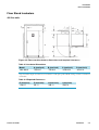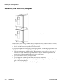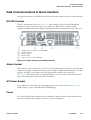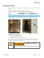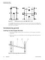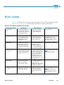
1
©
2012 Thermo Fisher Scientific Inc. All rights reserved.
These operating instructions are protected by copyright. Rights resulting thereof, particularly reprint, photomechanical
or digital postprocessing or reproduction, even in part, are only allowed with the written consent of Thermo Fisher Scientific.
This regulation does not apply to reproductions for in-plant use.
The contents of this operating instructions manual may change at any time and without any prior notice. In case of conflicting translations into foreign languages the German-language version of these operating instructions shall be binding.
Trademarks
Heratherm™ is a registered trademark of Thermo Scientific.
Thermo Scientific is a brand owned by Thermo Fisher Scientific, Inc.
All other trademarks mentioned in the operating instructions are the exclusive property of the respective manufacturers.
Thermo Fisher Scientific
Robert-Bosch-Straße 1
D - 63505 Langenselbold
Germany
Thermo Electron LED GmbH is an affiliate to:
Thermo Fisher Scientific Inc.
81 Wyman Street
Waltham, MA 02454
USA
Thermo Fisher Scientific Inc. provides this document to its customers with a product purchase to use in the product operation. This document is copyright protected and any reproduction of the whole or any part of this document is strictly
prohibited, except with the written authorization of Thermo Fisher Scientific Inc.
The contents of this document are subject to change without notice.
All technical information in this document is for reference purposes only. System configurations and specifications in this
document supersede all previous information received by the purchaser.
Thermo Fisher Scientific Inc. makes no representations that this document is complete, accurate or error-free and
assumes no responsibility and will not be liable for any errors, omissions, damage or loss that might result from any
use of this document, even if the information in the document is followed properly.
This document is not part of any sales contract between Thermo Fisher Scientific Inc. and a purchaser. This document
shall in no way govern or modify any Terms and Conditions of Sale, which Terms and Conditions of Sale shall govern
all conflicting information between the two documents.
i-ii
Heratherm
Thermo Scientific
C
Contents
Chapter 1 Safety Notes ..................................................................................................................... 1-1
Basic Operating Precautions ............................................................................................................... 1-1
Operational Safety Rules .................................................................................................................... 1-2
Warranty ............................................................................................................................................ 1-2
Explanation of Safety Information and Symbols ................................................................................. 1-3
Safety Notes and Symbols Used Throughout These Operating Instructions ................................... 1-3
Additional Symbols for Safety Information..................................................................................... 1-4
Symbols on the Incubator............................................................................................................... 1-5
Intended Purpose of the Incubator ..................................................................................................... 1-6
Intended Purpose of the Incubator ................................................................................................. 1-6
Incorrect Use .................................................................................................................................. 1-6
Standards and Directives .................................................................................................................... 1-6
Chapter 2 Delivery of the Incubator................................................................................................. 2-1
Packaging ........................................................................................................................................... 2-1
Acceptance Inspection ........................................................................................................................ 2-1
Scope of Supply .................................................................................................................................. 2-2
Chapter 3 Installation........................................................................................................................ 3-1
Ambient Conditions........................................................................................................................... 3-1
Location Requirements................................................................................................................... 3-1
Intermediate Storage........................................................................................................................... 3-2
Room Ventilation............................................................................................................................... 3-2
Space Requirement ......................................................................................................................... 3-3
Installation Built-in Units............................................................................................................... 3-3
Table-top incubators ...................................................................................................................... 3-4
Floor Stand Incubators ................................................................................................................... 3-5
Transport ........................................................................................................................................... 3-7
Stacking kit ........................................................................................................................................ 3-9
Installing the Stacking Feet................................................................................................................. 3-9
Installing the Stacking Adapter ......................................................................................................... 3-10
Installing the Anti-tilt Anchor .......................................................................................................... 3-11
Floor stand unit spacers .................................................................................................................... 3-13
Chapter 4 Product Description ........................................................................................................ 4-1
Heratherm IMH Series Incubator Overview....................................................................................... 4-1
Heratherm IMH-S Incubator Overview ............................................................................................. 4-4
Safety Devices................................................................................................................................... 4-11
Work Space Atmosphere .................................................................................................................. 4-11
Door Switch ..................................................................................................................................... 4-11
Sensing and Control System ............................................................................................................. 4-12
Thermo Scientific
Heratherm
i
Contents
Data Communications & Alarm Interface ........................................................................................ 4-13
RS-232 Interface........................................................................................................................... 4-13
Alarm Contact.............................................................................................................................. 4-13
AC Power Socket.......................................................................................................................... 4-13
Fuses............................................................................................................................................. 4-13
Work Space Components ................................................................................................................. 4-14
Inner Chamber ............................................................................................................................. 4-14
Connecting Nozzles for Fresh-air Filters (Accessory Items) ........................................................... 4-14
Access Port ................................................................................................................................... 4-15
Tube Access Ports............................................................................................................................. 4-17
Chapter 5 Installation procedures ................................................................................................... 5-1
Table-top incubators .......................................................................................................................... 5-1
Installing the Shelf System .................................................................................................................. 5-1
Initial Installation ........................................................................................................................... 5-1
Installing the Perforated Shelves ......................................................................................................... 5-2
Preparing the useable space................................................................................................................. 5-2
Installation or Removal of the Support Rails................................................................................... 5-3
Installing and Uninstalling the Air Baffle........................................................................................ 5-4
Levelling the Incubator ................................................................................................................... 5-4
Commissioning of floor stand incubators ........................................................................................... 5-5
Installing/Removing air baffles (IMH-S Series)............................................................................... 5-5
Commissioning, general ..................................................................................................................... 5-6
Installing the Shelf Support Brackets .............................................................................................. 5-6
Installing the Perforated Shelves ..................................................................................................... 5-7
Mains connection ............................................................................................................................... 5-7
Connecting to the Power Supply Source......................................................................................... 5-8
Connecting the RS-232 Interface ....................................................................................................... 5-9
Interconnecting the Incubator with a Computer............................................................................. 5-9
Wiring the Alarm Contact................................................................................................................ 5-11
Functional Description ................................................................................................................. 5-11
Alarm Relay Specifications............................................................................................................ 5-11
Connection Example .................................................................................................................... 5-12
Chapter 6 Operation.......................................................................................................................... 6-1
Preparing the Incubator...................................................................................................................... 6-1
Starting Operation.............................................................................................................................. 6-1
Chapter 7 Handling and Control ...................................................................................................... 7-1
Powering Up ...................................................................................................................................... 7-6
Switching the Incubator Off / Powering Down .................................................................................. 7-6
Temperature Set Value ....................................................................................................................... 7-7
Timer ................................................................................................................................................. 7-8
Setting a Fixed-time On or Off Timer.......................................................................................... 7-10
Setting a Weekly Timer ................................................................................................................ 7-11
Stopping a Timer.......................................................................................................................... 7-13
Power Outlet (table-top incubators only).......................................................................................... 7-15
Decontamination.............................................................................................................................. 7-16
Fan ................................................................................................................................................... 7-19
Table-top incubators ........................................................................................................................ 7-19
ii
Heratherm
Thermo Scientific
Contents
Floor stand incubators.......................................................................................................................7-20
Settings .............................................................................................................................................7-22
Error Log ......................................................................................................................................7-22
Calibration ....................................................................................................................................7-23
Date and Time ..............................................................................................................................7-24
Temperature Display Unit ............................................................................................................7-27
Chapter 8 Shut-down .........................................................................................................................8-1
Shutting the Incubator Down .............................................................................................................8-1
Chapter 9 Cleaning and Disinfection ...............................................................................................9-1
Cleaning..............................................................................................................................................9-1
Cleaning Exterior Surfaces...............................................................................................................9-1
Wipe / Spray Disinfection ...................................................................................................................9-1
Preparing the Manual Wipe/Spray Disinfection ..............................................................................9-2
Predisinfection ................................................................................................................................9-3
Cleaning..........................................................................................................................................9-4
Final Disinfection............................................................................................................................9-4
Starting the Decontamination Routine............................................................................................9-4
Chapter 10 Maintenance....................................................................................................................10-1
Inspections and Checks .....................................................................................................................10-1
Regular Checks..............................................................................................................................10-1
Semi-annual Inspection .................................................................................................................10-1
Service Intervals.................................................................................................................................10-2
3-monthly service ..........................................................................................................................10-2
Annual Service...............................................................................................................................10-2
Preparing Temperature Calibration...................................................................................................10-3
Comparison Measurement Procedure................................................................................................10-3
Temperature Calibration Procedure ..................................................................................................10-4
Replacing the Door Seal ....................................................................................................................10-4
Replacing the Power Cord.................................................................................................................10-5
Returns for Repair.............................................................................................................................10-5
Chapter 11 Disposal...........................................................................................................................11-1
Overview of Materials Used ..............................................................................................................11-1
Chapter 12 Error Codes.....................................................................................................................12-1
Chapter 13 Technical Data ................................................................................................................13-1
Chapter 14 Spare Parts and Accessories ........................................................................................14-1
Chapter 15 Device Log ......................................................................................................................15-1
Chapter 16 Contact ............................................................................................................................16-1
Thermo Scientific
Heratherm
iii
Contents
iv
Heratherm
Thermo Scientific
L
List of Figures
Figure 3-1 Table-top incubators, dimensions and required clearances .................................................................... 3-4
Figure 3-2 Floor stand incubators, dimensions and required clearances.................................................................. 3-5
Figure 3-3 Floor stand incubators, dimensions and required clearances.................................................................. 3-6
Figure 3-4 Lift Points............................................................................................................................................. 3-7
Figure 4-1 Heratherm IMH 60/ IMH 100/ IMH 180 Front View........................................................................ 4-2
Figure 4-2 Heratherm IMH 60/ IMH 100/ IMH 180 Rear View.......................................................................... 4-3
Figure 4-3 Heratherm IMH 60-S/ IMH 100-S/ IMH 180-S Series Front View .................................................... 4-5
Figure 4-4 Heratherm IMH 60-S / IMH 100-S / IMH 180-S Series Rear View .................................................... 4-6
Figure 4-5 Heratherm IMH 400-S Series Front View ............................................................................................ 4-7
Figure 4-6 Heratherm IMH 400-S Rear View ....................................................................................................... 4-8
Figure 4-7 Heratherm IMH 750-S Front View...................................................................................................... 4-9
Figure 4-8 Heratherm IMH 750-S Rear View ....................................................................................................... 4-10
Figure 4-9 Sensor System (for table-top incubators)............................................................................................... 4-12
Figure 4-10 Sensor System (for floor stand incubators) .......................................................................................... 4-12
Figure 4-11 Signal Interfaces and Power Socket ..................................................................................................... 4-13
Figure 4-12 Connecting Nozzle for Fresh-air Filters (Accessory Item).................................................................... 4-15
Figure 4-13 Shelf System ....................................................................................................................................... 4-16
Figure 4-14 Tube Access Ports............................................................................................................................... 4-17
Figure 5-1 Sliding the Retaining Spring into the Support Rail ............................................................................... 5-1
Figure 5-2 Installing the Shelving .......................................................................................................................... 5-2
Figure 5-3 Support Rail Installation....................................................................................................................... 5-3
Figure 5-4 Removing the Air Baffle ....................................................................................................................... 5-4
Figure 5-5 Removing the bottom plate .................................................................................................................. 5-5
Figure 5-6 Removing the left and right support profiles......................................................................................... 5-5
Figure 5-7 Removing the rear air baffle IMH 400-S / 750-S.................................................................................. 5-6
Figure 5-8 Shelf Support Bracket Installation ........................................................................................................ 5-6
Figure 5-9 Perforated Shelf .................................................................................................................................... 5-7
Figure 5-10 AC Power Supply Socket .................................................................................................................... 5-8
Figure 5-11 Alarm Contact Connection Example .................................................................................................. 5-12
Figure 7-1 Control Panel for Heratherm IMH Series and IMH-S Series Incubators. ............................................. 7-1
Figure 10-1 Door Seal Replacement ...................................................................................................................... 10-4
Thermo Scientific
Heratherm
i
List of Figures
ii
Heratherm
Thermo Scientific
1
Safety Notes
Basic Operating Precautions
These operating instructions describe Heratherm incubators.
Heratherm incubators have been manufactured to the latest state of the art and have been
tested thoroughly for flawless functioning prior to shipping. However, the incubator may
present potential hazards, particularly if it is operated by inadequately trained personnel or if it
is not used in accordance with the intended purpose. Therefore, the following must be
observed for the sake of accident prevention:
• Heratherm incubators must be operated by adequately trained and authorized professional
personnel.
• Heratherm incubators must not be operated unless these operating instructions have been
fully read and understood.
• The present operating instructions, applicable safety data sheets, plant hygiene guidelines
and the corresponding technical rules issued by the operator shall be used to create written
procedures targeted at personnel working with the subject matter device, detailing:
• the decontamination measures to be employed for the incubator and the accessories
used with it,
• the safety precautions to be taken when processing specific agents,
• the measures to be taken in case of accidents.
• Repair work on the incubator must be carried out only by trained and authorized expert
personnel.
• The contents of these operating instructions are subject to change at any time without
further notice.
• Concerning translations into foreign languages, the German version of these operating
instructions is binding.
• Keep these operating instructions close to the incubator so that safety instructions and
important information are always accessible.
• Should you encounter problems that are not detailed adequately in these operating
instructions, please contact Thermo Electron LED GmbH immediately for your own
safety.
Thermo Scientific
Heratherm
1-1
Safety Notes
Operational Safety Rules
Operational Safety Rules
The following rules must be heeded when working with Heratherm incubators:
• Observe the sample weight limits specified for your Heratherm incubator as a whole and
its shelving in particular; see “Technical Data” on page 13-1.
• Do not load the bottom of the interior workspace to avoid the risk of overheating any
samples placed there and to prevent the temperature sensor from being damaged.
• Arrange the samples evenly throughout the work space, making sure not to place them too
closely to the interior walls to ensure a uniform temperature distribution.
• Do not load your Heratherm incubator with substances that exceed the capabilities of the
available lab apparatus and Personal Protection Equipment to provide sufficient degrees of
protection to users and third parties.
• Check the door seal every six months for proper sealing performance and possible damage.
• Do not process any samples containing hazardous chemical substances that may be
released into the ambient air through defective seals or may cause corrosion or other
defects on parts of the Heratherm incubator.
Warranty
Thermo Fisher Scientific warrants the operational safety and functions of the Heratherm
incubators only under the condition that:
• the incubator is operated and serviced exclusively in accordance with its intended purpose
and as described in these operating instructions,
• the incubator is not modified,
• only original spare parts and accessories that have been approved by Thermo Scientific are
used (third-party spares without Thermo Scientific approval void the limited warranty),
• inspections and maintenance are performed at the specified intervals,
• an operation verification test is performed after each repair activity.
The warranty is valid from the date of delivery of the incubator to the customer.
1-2
Heratherm
Thermo Scientific
Safety Notes
Explanation of Safety Information and Symbols
Explanation of Safety Information and Symbols
Safety Notes and Symbols Used Throughout These Operating
Instructions
Indicates a hazardous situation which, if not avoided, will result
in death or serious injuries.
Indicates a hazardous situation which, if not avoided, could result
in death or serious injuries.
Indicates a situation which, if not avoided, could result in damage to
equipment or property.
Is used for useful hints and information regarding the application.
Thermo Scientific
Heratherm
1-3
Safety Notes
Explanation of Safety Information and Symbols
Additional Symbols for Safety Information
Wear safety gloves!
Wear safety goggles!
Harmful liquids!
Electric shock!
Hot surfaces!
Fire hazard!
Explosion hazard!
Suffocation hazard!
Biological hazard!
Contamination hazard!
Danger of tipping!
1-4
Heratherm
Thermo Scientific
Safety Notes
Explanation of Safety Information and Symbols
Symbols on the Incubator
Observe operating instructions
Mark of conformity USA/Canada
120 Volts AC power socket
Alarm contact
Thermo Scientific
Heratherm
1-5
Safety Notes
Intended Purpose of the Incubator
Intended Purpose of the Incubator
Intended Purpose of the Incubator
Heratherm incubators are laboratory devices for preparing and cultivating cell and tissue
cultures. The devices employ precision temperature control for simulating the specific
physiological ambient conditions for these cultures.
Incorrect Use
To avoid the risk of explosion do not load the incubator with tissue, material, or liquids that:
• are easily flammable or explosive,
• release vapor or dust that forms combustible or explosive mixtures when exposed to air,
• release poisons,
• do not pour any liquids on the bottom of the interior surface or into a collecting basin
inside the unit.
• release dust
• exhibit exothermic reactions
• are pyrotechnical substances
• refrain also from pouring any liquids onto the internal base plate or inserting bowls filled
with liquids into the sample compartment.
Standards and Directives
The incubator complies with the following standards and guidelines:
• IEC EN 61010 - 1, IEC EN 61010 - 2 - 010
• Low Voltage Directive 2006/95/EC
• EMC Directive 2004/108/EC
Additionally, the incubator is in compliance with many other international standards,
regulations and directives not listed here. Should you have any questions regarding compliance
with national standards, regulations and directives applicable for your country, please contact
your Thermo Fisher Scientific sales organization.
1-6
Heratherm
Thermo Scientific
2
Delivery of the Incubator
Packaging
Heratherm incubators are delivered in a rugged packaging box. All packaging materials can be
separated and are reusable:
Packaging materials
Packaging carton:
Recycled paper
Foam elements:
Styrofoam (CFC-free)
Pallet:
Chemically untreated wood
Packaging film:
Polyethylene
Packaging ribbons:
Polypropylene
Acceptance Inspection
After the incubator has been delivered, check the delivery immediately for:
• completeness,
• possible damage.
If components are missing or damage is found on the incubator or the packaging, in particular
damage caused by humidity and/or water, please notify the carrier as well as Thermo Scientific
Technical Support immediately.
Risk of injury
Should sharp edges have formed in damaged areas or elsewhere
on the device, take all necessary precautions to protect
personnel handling the incubator. For example, have them wear
protective gloves and other personal protection equipment.
Thermo Scientific
Heratherm
2-1
Delivery of the Incubator
Scope of Supply
Scope of Supply
Incubators
2-2
Quantity of components supplied (pieces)
IMH Series
IMH-S Series
Perforated shelves
2
Support rail for shelf table-top incubators
2
Shelf support
4
Power cord
1
Connector, potential-free contact
1
Clip springs for table-top incubators
2
Plug
1
Anti-tilt anchor
1
Operating manual
1
Short reference guide
1
Heratherm
Thermo Scientific
3
Installation
Ambient Conditions
Location Requirements
Built-in incubators can, heating and drying ovens must be operated with an air exhaust system
and exhaust hose (only original Thermo accessory should be used).
For safety reasons, the installation space should be made of non-combustible materials,
according to DIN 4102.
During installation of built-in units, ensure that the
escaping air will be safely discharged out of the
installation space.
The incubator must only be operated in a location that meets all of the ambient condition
requirements listed below:
• Installation location indoors in dry areas free from drafts.
• The dust burden may not exceed the contamination category 2 based on EN 61010-1.
Using the incubator in an atmosphere with electrically conductive dust is prohibited.
• The minimal distance to adjacent surfaces must be observed on all sides (see Section
“Space Requirement” on page 3-3)
• The operating room must be equipped with appropriate ventilation.
• Solid, level, fire-proof surface; no flammable materials opposite to the rear panel of the
incubator.
• Vibration-proof substructure (floor stand, lab table) capable of bearing the dead weight of
the incubator and its accessories (particularly if two devices are stacked).
• The electrical circuitry of the incubator has been designed for an operating height of up to
2000 m above sea level.
• Relative humidity up to 80% (maximum; preferably 60-70%), non condensing.
• Should condensation exist, wait until the moisture has evaporated completely before
connecting the incubator to a power source and powering up.
• The ambient temperature must be within a range of +18 °C to +32 °C (64.4 °F to 89.6 °F).
• Avoid direct exposure to sunlight.
Thermo Scientific
Heratherm
3-1
Installation
Intermediate Storage
• Devices that produce excessive amounts of heat must not be placed near the incubator.
• Place the incubator on a floor stand (option; to be ordered separately), never on the lab
floor. This prevents the penetration of dust or dirt into the device.
• Power line voltage variations must not exceed ±10 % of the nominal voltage.
• Transient surges must lie within the range of levels that normally occur in the power
supply system. The impulse withstand voltage based on surge category II of
IEC 60364-4-443 shall be applied at the nominal voltage level.
• Consider installing one dedicated upstream circuit breaker per incubator to avoid multiple
device failures in case of an electrical fault.
Contamination hazard
Do not place the incubator directly on the lab floor, but mount it
on the floor stand or on a lab work surface (option; to be ordered
separately). Contaminants, such as bacteria, viruses, fungi,
prions, and other biological substances may use the open door to
migrate easily from the floor into the incubator’s work space.
Intermediate Storage
When the incubator is placed in intermediate storage, which is permissible for a maximum of
four weeks, make sure that the ambient temperature is between 20 °C to 60 °C (68 °F to
140 °F) and the maximum relative humidity does not exceed 90%, non-condensing.
Room Ventilation
Heat dissipating from the incubator during continuous operation may cause a change in the
room climate.
• Therefore, the incubator must only be installed in rooms with sufficient ventilation.
• Do not install the incubator in room recesses without ventilation.
• When several devices are to be placed in the same room, additional ventilation may have
to be provided as necessary.
• To avoid any impact of the heat dissipated by the incubator on the ambient climate the
room must be vented by means of a laboratory-grade ventilation system that complies
with applicable local and national health and safety regulations and has sufficient capacity.
• If excessive temperatures tend to occur in the operating room, be sure to provide a thermal
protection means that cuts out the power supply to mitigate the impact of
overtemperature scenarios.
3-2
Heratherm
Thermo Scientific
Installation
Room Ventilation
Space Requirement
For built-in units following clearances should be kept:
Fig. 3
A, B, C and D see Operating Instructions of the unit.
E (mm/inch)
F (mm/inch)
G (mm/inch)
H (mm/inch)
100 / 4
50 / 2
80 / 3.2
30 / 1.2
Installation Built-in Units
IGS
Clearances without exhaust hose.
IMH/IMH-S
Clearances, close air port with plug, supplied with the unit.
OGS/OMS
Clearances, with additional space to operate to air slide, with air exhaust system
and exhaust hose Ø 40 mm (1.58 in)/1.5 m (59 in) (original Thermo accessory),
shortened to required length.
OGH/OGH-S
OMH/OMH-S
Clearances, with air exhaust system and exhaust hose Ø 40 mm (1.58 in)/1.5 m
(59 in) (original Thermo accessory), shortened to required length. Operating
temperature up to max. 250 °C (482 °F).
After connecting the built-in unit to the electrical
power supply, avoid damaging the power cord, then
sliding into the installation position.
When installing the incubator, make sure that the installation and supply connections remain
freely accessible.
The specified side clearances represent minimum distances.
Thermo Scientific
Heratherm
3-3
Installation
Room Ventilation
Table-top incubators
Figure 3-1 Table-top incubators, dimensions and required clearances
Table 3-1 Incubator Dimensions
Model
A (mm)
B (mm)
C (mm)
D (mm)
IMH 60
530/20.1
565/22.2
720/28.3
540/21.3
IMH 100
640/25.2
565/22.2
820/32.3
650/25.6
IMH 180
640/25.2
738/29.1
920/36.2
650/25.6
IMH 60-S
530/20.1
565/22.2
720/28.3
540/21.3
IMH 100-S
640/25.2
565/22.2
820/32.3
650/25.6
IMH 180-S
640/25.2
738/29.1
920/36.2
650/25.6
* Depth of handle /display (66 mm/2.6 in) not included in overall depth specified; height of adjustable feet (36 mm/1.4 in)
not included in overall height specified.
Table 3-2 Required Clearances
3-4
E (mm)
F (mm)
G (mm)
H (mm)
80/3.1
50/2.0
200/7.9
300/11.8
Heratherm
Thermo Scientific
Installation
Room Ventilation
Floor Stand Incubators
400 liter units
Figure 3-2 Floor stand incubators, dimensions and required clearances
Table 3-3 Incubator Dimensions
Model
A (mm/inch)
B (mm/inch)
C (mm/inch)
D (mm/inch)
IMH 400-S
755/29.7
770/30.3
1655/65.2
810/31.9
* Depth of handle /display (66 mm/2.6 in) not included in overall depth specified. Width of hinge (23 mm) not included in
overall width.
Table 3-4 Required Clearances
E (mm/inch)
F (mm/inch)
H (mm/inch)
I (mm/inch)
120/4.7
50 / 2
200 / 8
200/7.9
Thermo Scientific
Heratherm
3-5
Installation
Room Ventilation
750 liter units
Figure 3-3 Floor stand incubators, dimensions and required clearances
Table 3-5 Incubator Dimensions
Model
A (mm/inch)
B (mm/inch)
C (mm/inch)
D (mm/inch)
IMH 750-S
1215 / 47.8
770/30.3
1655 / 65.2
670/26.4
* Depth of handle /display (66 mm/2.6 in) not included in overall depth specified. Width of hinge (23 mm) not included in
overall width.
Table 3-6 Required Clearances
3-6
E (mm/inch)
F (mm/inch)
H (mm/inch)
I (mm/inch)
120/4.7
50/2.0
200/7.9
350/13.8
Heratherm
Thermo Scientific
Installation
Transport
Transport
Table-top incubators
For transport, do not lift the incubator using the doors or components attached to the
incubator as lift points.
Figure 3-4 Lift Points
Heavy loads! Lift with care!
To avoid injury through physical strain, such as strain traumata
and slipped discs, do not attempt to lift the incubator alone!
To avoid injury through dropped loads, be sure to wear Personal
Protection Equipment, such as safety shoes, when lifting the
incubator.
To avoid crushing your fingers or hands (particularly in a closing
door) or damaging the incubator, do not use any other lift points
than those indicated in the illustration above.
Thermo Scientific
Heratherm
3-7
Installation
Transport
Floor stand incubators
The floor stand incubators come equipped with four (4) casters. The lever for releasing the
caster is located above the locking lever. After positioning the unit in its installation location
ensure that the locking levers are pressed down on the casters.
To ensure the degree of stability specified by safety requirements the front casters must be
turned so that they are facing forward after the unit has been positioned in its installation
location and the locking levers pressed down on these casters.
Danger of tipping when moving!
Before moving the unit, ensure that it has been unplugged.
Move the Heratherm floor stand incubators with caution.
Quick starts and stops can result in tipping!
Always ensure that the doors are closed when moving the unit.
3-8
Heratherm
Thermo Scientific
Installation
Stacking kit
Stacking kit
The stacking adapter is available only for table-top incubators.
Material Number
Description
50126665
Stacking adapter Heratherm 60L
50126666
Stacking adapter Heratherm 100L
50126667
Stacking adapter Heratherm 180L
Scope of delivery:
1 Stacking adapter
1 Anti-tilt anchor
1 Plastic bag with 2 stacking feet and 2 M4x16 Torx screws.
Required Tools:
Slotted screwdriver 5,5x100 or Torx screwdriver 20x100.
Installing the Stacking Feet
Remove the left and right blank plugs at the top.
Install the stacking feet with the enclosed screws using a slotted or Torx screwdriver.
Thermo Scientific
Heratherm
3-9
Installation
Installing the Stacking Adapter
Installing the Stacking Adapter
1
Anti-tilt anchor
Stack as follows when using a stacking adapter (numbers denote incubator volumes in liters):
• for 60 l or 100 l on 180 l use stacking adapter Heratherm 180L,
• for 60 l on 100 l use stacking adapter Heratherm100L.
To prevent the top device from slipping and dropping down, the following requirements must
be fulfilled before devices may be stacked:
• Only two units may be stacked together. When stacking devices with the same type of
enclosure, yet with a different footprint the device with the smaller footprint must be
placed on top of the one with the larger footprint at all times.
• The bottom device must be correctly levelled.
• Place the corresponding stacking adapter.
• The levelling feet on the top device must be screwed in all the way.
• The levelling feet of the top device must be aligned with and placed exactly on the stacking
pads of the stacking adapter.
• The anti-tilt anchor must be installed at the top device.
3-10
Heratherm
Thermo Scientific
Installation
Installing the Anti-tilt Anchor
Installing the Anti-tilt Anchor
Table-top incubators
The anti-tilt anchor secures the top device in a stack to a solid part of a building. The anti-tilt
anchor is to be mounted on the side opposite of the door hinges.
Bend the fixing tabs of the anti-tilt anchor up on one side and down on the other by an angle
of approx. 90°.
1. Do not use this position if the door is hinged on this side. Right-hand hinges represent the
standard configuration.
2. Preferred position.
3. Alternative position. Do not use if the door is hinged on this side.
Remove the bracket screws. Use the preferred position, if possible.
Fix the anti-tilt anchor with the bracket side down to the unit.
Position the unit with the anti-tilt anchor to in an angle of approx. 90° +/- 20%.
Take care that the stacking feet of the unit are still in correct place on the lower unit or on the
stacking adapter.
Fix the anti-tilt anchor to a solid part of the building.
Floor stand incubators
Heratherm floor stand incubators must always be attached to the wall using
two (2) retaining brackets on the outer left and right side on the back of the
unit.
Thermo Scientific
Heratherm
3-11
Installation
Installing the Anti-tilt Anchor
Remove the screws.
Attach the end of the retaining bracket that is facing downward to the unit.
Align the device at roughly 90°, +/-20° to the retaining bracket.
Affix the retaining bracket to the wall.
Unsafe part of the building!
Install the anti-tilt anchor to a solid part of the building, which is able for shoring
loads.
The installation has to be carried out by qualified personnel only.
The connection to the building must be carried out with appropriate screws and
dowels according to the consistence of the building part.
Additionally, the following caution notes must be heeded at all times:
Risk of overheating with stacked devices
To avoid the risk of electrical components and the outer enclosure overheating
or temperature control failing due to insufficient ventilation, do not exceed the
specified stacking height!
Risk of tipping and dropping of stacked devices
You should be aware at all times that stacked devices do not form a stable unit,
even when the stacking pads and frames are correctly used. The top device may
tip over and drop down when being transported in a stack. To avoid injury to
persons and damage to equipment, do not attempt to move stacked devices as
a unit! Separate and move each device one by one, then restack them.
3-12
Heratherm
Thermo Scientific
Installation
Floor stand unit spacers
Floor stand unit spacers
The spacer on the electrical module must be pulled out and fixed in place before installing the
floor stand unit at its installation location.
1
Loosen the 2 screws
2
Pull out the spacer and slide the screws into the recesses
3
Tighten the two screws
Thermo Scientific
Heratherm
3-13
Installation
Floor stand unit spacers
3-14
Heratherm
Thermo Scientific
4
Product Description
This section describes Heratherm advanced protocol microbiological incubators for high-end
laboratory applications, which are available in two different versions distinguished by safety
level:
• Heratherm IMH Series advanced protocol microbiological fan convection incubators (see
“Heratherm IMH Series Incubator Overview” on page 4-1);
• Heratherm IMH-S Series advanced protocol security microbiological fan convection
incubator for more exacting safety level requirements (see “Heratherm IMH-S Incubator
Overview” on page 4-4).
Heratherm IMH Series Incubator Overview
IMH Series advanced protocol microbiological incubators come equipped with the following
features:
• high-precision work space temperature control, adjustable in steps of one-tenth of a degree
up to 105°C (221°F)
• a variable-speed work space fan, adjustable on the control panel
At high ambient temperatures the maximum speed is reduced.
•
•
•
•
Thermo Scientific
countdown, fixed-time, and weekly timers for timed process control
two perforated shelves
an access port for tubing, sensor leads, etc.
power outlet
Heratherm
4-1
Product Description
Heratherm IMH Series Incubator Overview
The individual features of IMH Series incubators are shown in the figures below.
Figure 4-1 Heratherm IMH 60/ IMH 100/ IMH 180 Front View
[1] Outer door
[2] Door latch cutout
[3] Door latch and handle
[4] Door hinge, lower
[5] Levelling foot
[6] Nameplate
[7] Temperature sensor
[8] Support rail for perforated shelf
[9] Shelf support
[10] Fan opening, air baffle
[11] Door hook catch
[12] Air baffle
[13] Door seal
[14] Stacking pad
[15] Spring
[16] Power outlet
[17] Access port
[18] [19] Glass door
4-2
Heratherm
Thermo Scientific
Product Description
Heratherm IMH Series Incubator Overview
Figure 4-2 Heratherm IMH 60/ IMH 100/ IMH 180 Rear View
[1] Door latch and handle
[2] Control panel
[3] Stacking pad
[4] Access port
[5] Fan
[6] Electronics compartment
[7] Levelling foot
[8] Sample sensor connection (IMH-S only)
Thermo Scientific
Heratherm
4-3
Product Description
Heratherm IMH-S Incubator Overview
Heratherm IMH-S Incubator Overview
IMH-S Series advanced protocol security microbiological mechanical convection incubators
come equipped with the features also found in IMH Series devices, including:
• high-precision work space temperature control, adjustable in steps of one-tenth of a degree
up to 105 °C (221 °F)
• a variable-speed work space fan, adjustable on the control panel (at high ambient
temperatures the maximum speed is reduced)
At high ambient temperatures the maximum speed is reduced.
• countdown, fixed-time, and weekly timers for timed process control
• two perforated shelves for sample containers
• an access port for tubing, sensor leads, etc.
Additionally, IMH-S Series incubators offer the following extra functionality:
• Monitoring of lower temperature
• Connection for Acceptable temperature sensor (accessory, must be ordered separately)
• a lockable door to secure a running process against unauthorized access
• a door switch and indicator on the control panel to indicate that the door is open
• a built-in, fully automatic decontamination routine
4-4
Heratherm
Thermo Scientific
Product Description
Heratherm IMH-S Incubator Overview
The individual features of IMH-S Series incubators are shown in the figures below.
Figure 4-3 Heratherm IMH 60-S/ IMH 100-S/ IMH 180-S Series Front View
[1] Outer door
[2] Door switch
[3] Door latch and handle, with lock
[4] Door hinge, lower
[5] Levelling foot
[6] Nameplate
[7] Temperature sensor
[8] Support rail for perforated shelf
[9] Shelf support
[10] Fan opening, air baffle
[11] Door hook catch
[12] Air baffle
[13] Door seal
[14] Stacking pad
[15] Spring
[16] [17] Access port
[18] [19] Glass door
Thermo Scientific
Heratherm
4-5
Product Description
Heratherm IMH-S Incubator Overview
8
Figure 4-4 Heratherm IMH 60-S / IMH 100-S / IMH 180-S Series Rear View
[1] Door latch and handle
[2] Control panel
[3] Stacking pad
[4] Access port
[5] Fan
[6] Electronics compartment
[7] Levelling foot
[8] Sample Sensor connection
4-6
Heratherm
Thermo Scientific
Product Description
Heratherm IMH-S Incubator Overview
Figure 4-5 Heratherm IMH 400-S Series Front View
[1] Outer door
[2] Door latch
[3] Unit caster
[4] Air baffle
[5] Perforated shelf
[6] Door hook catch
[7] Glass door latch
[8] Temperature sensor
[9] Access port
[10] Glass door
[11] [12] [13] [14] [15] [16] [17] [18] [19] [20] [21] Fan opening, air baffle
Thermo Scientific
Heratherm
4-7
Product Description
Heratherm IMH-S Incubator Overview
21
Figure 4-6 Heratherm IMH 400-S Rear View
[1] Outer door
[2] [3] Unit caster
[4] [5] [6] [7] [8] [9] [10] [11] Access port
[12] Anti-tilt anchor
[13] Electronics compartment
[14] Inlet air tube
[15] Hinge
[16] Door handle
[17] Display
[18] Nameplate on sidewall
[19] [20] [21] Exhaust air tube
[22] Fan
4-8
Heratherm
Thermo Scientific
Product Description
Heratherm IMH-S Incubator Overview
2
9
Figure 4-7 Heratherm IMH 750-S Front View
[1] Outer door
[2] Door hook catch
[3] Unit caster
[4] Air baffle
[5] Perforated shelf
[6] Door latch
[7] Glass door latch
[8] Temperature sensor
[9] Access port
[10] Glass door
[11] [12] [13] [14] [15] [16] [17] [18] [19] [20] [21] Fan opening, air baffle
Thermo Scientific
Heratherm
4-9
Product Description
Heratherm IMH-S Incubator Overview
21
Figure 4-8 Heratherm IMH 750-S Rear View
[1] Outer door
[2] [3] Unit caster
[4] [5] [6] [7] [8] [9] [10] [11] Access port
[12] Anti-tilt anchor
[13] Electronics compartment
[14] [15] Hinge, right
[16] Door handle
[17] Display
[18] Nameplate on sidewall
[19] Hinge, left
[20] Inlet air tube
[21] Exhaust air tube
[22] Fan
4-10
Heratherm
Thermo Scientific
Product Description
Safety Devices
Safety Devices
The incubators are equipped with the following safety features:
• a sample protection feature that safeguards the samples against destruction through
overheating in case of contoller failure;
• an overheat protection cut-out feature that shuts down the incubators IMH-S completely
when excessive temperatures occur in the workspace;
• an alarm relay that is energized, along with audible and visual alarms, to indicate errors
encountered during operation;
• dual fuses rated at 16 amperes.
Work Space Atmosphere
To ensure undisturbed operation, the ambient temperature in the operating room must be at
least 18 °C (64.4 °F).
The heating system uses this temperature threshold to control the ambient temperature plus
5 °C (41 °F) up to the maximum of 105 °C (221 °F).
Door Switch
Heratherm IMH 60/100/180/400/750 S incubators come with a door switch [1] integrated
into the latch mechanism. If the door switch is activated by opening the door, heating
operations in the work space are suspended and an icon is illuminated in the display window
(see D4 in figure 7-1 on page 7-1).
If the door remains open for more than 30 seconds, a short audible alarm is sounded in
addition to the icon in the display window. If the door is left open for more than 10 minutes,
an audible alarm is sounded, a “door open” (E001) alarm message appears in the display and is
issued through the RS-232 interface, and the alarm relay is energized.
Thermo Scientific
Heratherm
4-11
Product Description
Sensing and Control System
Sensing and Control System
The PT 100-type sensor for the control of the work space temperature and for the thermal
protection [1] is installed on the bottom of table-top incubators and in the top of floor stand
incubators.
Figure 4-9 Sensor System (for table-top incubators)
Figure 4-10 Sensor System (for floor stand incubators)
The work space temperature sensor provides the inputs to the incubator’s built-in controller,
which continuously compares the measured values to the user-specified set value and adjusts
the heaters according to the result.
Do not remove the protection hose from the sensor.
Protect the sensor from mechanical damage.
The unit features a thermal protection function that is factory-preprogrammed and not
adjustable. It protects the cultures in the work space from overheating: Thermal protection
kicks in on a brief violation of the upper limit, based on the defined setpoint temperature, at
between 2 and 3 °C (35.6 °F and 37.4 °F) (37 °C (99 °F): 2 °C (35.6 °F), > 50 °C (122 °F):
3 °C (37.4 °F)), automatically reducing the work space temperature to the user-specified set
value and allowing the incubation process to be continued even in case of a controller
malfunction. If the thermal protection is activated, the error message (E111) “Temperature
too high” appears in the display window and an audible alarm is sounded.
When the user acknowledges the error message, the red alarm icon (D4 in figure 7-1 on
page 7-1) is illuminated and the Temperature Set Value icon (see table 7-3 on page 7-4) is
highlighted by a red border to indicate that thermal protection has kicked in.
4-12
Heratherm
Thermo Scientific
Product Description
Data Communications & Alarm Interface
Data Communications & Alarm Interface
All signal connections are installed in the electrical interface panel at the rear of the incubator.
RS-232 Interface
The RS- 232 interface (item 2 in figure 4-11 below) may be used to connect Heratherm
incubators to the serial interface port of a computer to allow for the computer-aided
acquisition and documentation of major operating parameters (temperature, error codes, etc.).
[1]
[2]
[3]
[4]
[5]
Sample Sensor connection (only IMH-S)
RS 232 interface
Alarm contact
Power socket
2 fuses 2 A, for socket and lamp
Figure 4-11 Signal Interfaces and Power Socket
Alarm Contact
The incubator can be connected to an on-site, external alarm system (such as a private branch
telephone exchange, a facility monitoring system, visual or audible alarm indicators). For this
purpose, the devices come with a pre-wired potential-free alarm contact (item 3 in
figure 4-11). The alarm contact is energized whenever an error occurs in an internal control
loop or the incubator’s electrical circuits or hardware.
AC Power Socket
The incubator is connected to the AC supply mains via the socket (item 4 in figure 4-11),
which accepts a power cord with an IEC standard plug.
Fuses
Two 16 A slow-blow fuses mounted on the incubator’s main electronic circuit board protect
internal circuitry from the impact of excessive power consumption.
Thermo Scientific
Heratherm
4-13
Product Description
Work Space Components
Replacement should only be carried out by skilled and authorized
qualified personnel of electrotechnology/signal engineering!
Fuse replacement
The device fuses are not user-serviceable. When the incubator exhibits
the typical signs of a blown fuse (no response to pressing the On/Off
button, control panel remains extinguished, no heating operation), call
Thermo Fisher Scientific Customer Service to have the fuses replaced.
Work Space Components
Inner Chamber
All components of the work space are made of corrosion-resistant stainless steel and have an
absolutely smooth and easy-to-clean surface. Any embossings have a large radius.
Connecting Nozzles for Fresh-air Filters (Accessory Items)
Observe the following note for IMH Series and IMH-S Series incubators with connecting
nozzles for fresh-air filters (accessory item).
Connecting nozzle for fresh-air filters
The connecting nozzle for the fresh-air filter (accessory item) may
neither be extended with nor be diverted through other tubing.
A fresh-air filter can be attached to the connecting nozzle. After puncturing the plastic cap the
fresh-air filter can be screwed onto the nozzle.
The connecting nozzle can be closed off using the 1/8” closure plug delivered with the unit
after opening the plastic cap.
The connecting nozzle for the Heratherm IMH 60/100/180 and IMH 60-S/100-S/180-S
incubators has a G 1/8” threaded fitting.
4-14
Heratherm
Thermo Scientific
Product Description
Work Space Components
Figure 4-12 Connecting Nozzle for Fresh-air Filters (Accessory Item)
Access Port
A re-sealable, capped access port (can be closed off using the plugs delivered with the unit)
(Heratherm IMH 60/100/180 and IMH 60-S/100-S/180-S/400-S/750-S only, see figure 4-7)
allows cables, hoses or additional sensor leads to be routed into the work space of the
incubator.
The access port [2] has a diameter of 42 mm.
Operating conditions
When accessories are to be operated in the work space of the
incubator, the ambient condition requirements must be observed (see
table below). The energy introduced into the work space has an impact
on the lower end of the temperature control range. When additional
heating sources are introduced into the work space, temperature control
may be adversely affected.
Shelf System
The incubator is supplied with two perforated shelves. The shelf support rails [1] have an
alternating pattern of oblong and round perforations spaced evenly at 30 mm, allowing the
shelf support brackets [8] to be inserted without any room for error, yet in a very flexible way
to accommodate any required height of sample container. The shelves [2] have an integrated
tilt protection and pull-out stop. For details on using the shelf system, see “Installing the Shelf
System” on page 5-1.
Thermo Scientific
Heratherm
4-15
Product Description
Work Space Components
[1]
[2]
[3]
[4]
[5]
Air Baffles
Retaining Springs (only for table-top incubators)
Support Rails
Shelf Support
Shelves
Figure 4-13 Shelf System
4-16
Heratherm
Thermo Scientific
Product Description
Tube Access Ports
Tube Access Ports
Heratherm incubators may be equipped with additional tube access ports in the side and top
panels.
Available tube access port options are listed in table 4-1 below.
Tabelle 4-1 Tube Access Ports for Heratherm Incubators (Option)
Model
Side Panel Mounted Port,
dia. in mm/inch
Top Panel Mounted Port,
dia. in mm/inch
IMH and IMH-S
24/0.95 or 58/2.28
24/0.95 or 58/2.28
The tube access ports are mounted in fixed locations in the side and top panels (see
figure 4-14).
1
3
2
Figure 4-14 Tube Access Ports
[1] Top panel mounted tube access port
[2] Side panel mounted tube access port
[3] Sealing cap for side panel mounted tube access port
Once the cables, tubes or other conduits have been inserted, the tube access ports must be
padded with the heat-resistant fiber pads shipped with the device and the cap must be
mounted to seal the port as far as possible.
Risk of Burning on Hot Surface
The surface around the tube access ports may become extremely
hot.
Thermo Scientific
Heratherm
4-17
Product Description
Tube Access Ports
4-18
Heratherm
Thermo Scientific
5
Installation procedures
Table-top incubators
Installing the Shelf System
The installation of the shelf system does not require any tools. The support rails are secured in
place by spring action. Once the shelf support brackets have been inserted into the rails, the
perforated shelves can be simply pushed onto their support hooks to complete the installation.
The support rails of the floor stand incubators cannot be removed.
Initial Installation
1. Peel off the protective foil from the support rails.
2. Push the retaining spring [1] into the guide on the support rail [2], making sure that the
locking nub [3] on the retaining spring safely engages with the matching hole in the
support rail.
.
Figure 5-1 Sliding the Retaining Spring into the Support Rail
Thermo Scientific
Heratherm
5-1
Installation procedures
Installing the Perforated Shelves
Installing the Perforated Shelves
The illustration below shows the placement of the shelf system elements.
[1]
[2]
[3]
[4]
[5]
Air Baffles
Retaining Springs (only for table-top incubators)
Support Rails
Shelf Support
Shelves
Figure 5-2 Installing the Shelving
Preparing the useable space
Upon delivery, Heratherm incubators are not in a sterile state. Before the initial start-up, the
incubator must be decontaminated.
The following work space components should be checked for cleanliness and disinfected prior
to use:
• Support rails,
• Shelf support,
• Perforated shelves,
• Useable space surfaces,
• Work space seals and gaskets,
• Glass door
5-2
Heratherm
Thermo Scientific
Installation procedures
Preparing the useable space
Cleaning and disinfection
For details about the cleaning and disinfection of the incubator, please
refer to “Cleaning” on page 9-1.
Installation or Removal of the Support Rails
Figure 5-3 Support Rail Installation
The embossings at [2] and [5] act as lateral guides for the support rails, while the embossings
at [1] and [6] secure the support rails in place. For the support rails to install correctly the
retaining spring [3] must be facing upwards.
1. Place the support rail [4] on the lower embossing [6] and tilt it upwards against the work
space side wall so that the rail is positioned over the two embossings at [5] and [2].
2. Clamp the retaining spring [3] behind the upper embossing [1].
3. To remove the support rails, pull the retaining spring tab down out of the embossing and
remove the support rail assembly.
Thermo Scientific
Heratherm
5-3
Installation procedures
Preparing the useable space
Installing and Uninstalling the Air Baffle
Heratherm IMH and IMH-S Series incubators are shipped from the factory with the air baffle
readily pre-installed. Before the air baffle can be removed from the back wall, the support rails
need to uninstalled.
Figure 5-4 Removing the Air Baffle
1. Losen the two screws [1] that hold the air baffle to the interior container back wall.
2. Grab the two retaining springs [2] at their tabs and pull them downwards out of the
embossings, then take off the air baffle from the back wall.
3. For the air baffle to install correctly, the retaining springs must be facing upwards. Place the
air baffle on the lower embossings and tilt it upwards against the back wall of the work space.
4. Clamp the two retaining springs [2] into the upper embossings.
5. Secure the air baffle against the interior container back wall by fastening the two screws at [1].
Levelling the Incubator
1. Position a bubble level onto the center shelf.
2. Manually adjust the levelling feet until the shelf is horizontally aligned in all directions.
Perform the adjustment of the levelling feet from left to right and from rear to front.
5-4
Heratherm
Thermo Scientific
Installation procedures
Commissioning of floor stand incubators
Commissioning of floor stand incubators
Installing/Removing air baffles (IMH-S Series)
The section below describes how to install/remove the bottom plate.
Figure 5-5
Removing the bottom plate
1. Loosen and remove the four (4) screws in the bottom plate and then remove the bottom
plate completely.
Figure 5-6
Removing the left and right support profiles
Loosen and remove the eight (8) screws for the left and right support profiles and then take
out the lateral air baffles.
Thermo Scientific
Heratherm
5-5
Installation procedures
Commissioning, general
Figure 5-7
Removing the rear air baffle IMH 400-S / 750-S
On the IMH-S 400 model loosen and remove the six (6) screws for the rear air baffle and for
model IMH-S 750 loosen and remove the six (6) screws for the top and bottom air baffles and
then remove the air baffle(s).
Commissioning, general
Installing the Shelf Support Brackets
1. Insert the shelf support bracket [3] into the perforations [1] of the support rail and tilt it
downwards.
2. Make sure that the two vertical elements [2] of the shelf support bracket butt against the
support rail.
Figure 5-8 Shelf Support Bracket Installation
5-6
Heratherm
Thermo Scientific
Installation procedures
Mains connection
Installing the Perforated Shelves
[1]
[2]
[3]
[4]
Rear Pull-out Stop
Tilt Protection Device
Front Pull-out Stop
Shelf
Figure 5-9 Perforated Shelf
1. Push the shelf [4] onto the shelf support brackets with the tilt protection devices [2] facing
the rear panel of the incubator.
2. Slightly raise the perforated shelf so that the pull-out stops [1] and [3] can slide over the
shelf support brackets.
3. Make sure that the shelves and both of their tilt protection devices are free to move over
the shelf support brackets.
Mains connection
Electric shock
Contact with live electrical components may cause a lethal electric
shock.
Before connecting the incubator to the power supply, check the
power cord and the plug for damage. Do not use damaged cables
for connecting the incubator to the power supply!
The incubator has a class I, protection-earthed enclosure. To minimize the risk of electrical
shock, use the AC power cord supplied to connect the incubator to a correctly installed and
protection-earthed power supply source, with the following features in place for each
incubator:
• T 16 A slow-blow fusing
• B 16 circuit breaker
Thermo Scientific
Heratherm
5-7
Installation procedures
Mains connection
Connecting to the Power Supply Source
1. Before connecting the incubator to the power source, check to see if the power supply
voltage corresponds with the specifications on the nameplate on the front of the incubator.
If the voltage (V) and current (A) ratings given are not as required, do not connect the
incubator to the power source!
2. Connect the IEC connector to the socket at the rear of the incubator.
3. Route the power cord along a path that does not cross exhaust air piping or passageways
and aisles.
With stacked devices, keep the power cord away from hot spots on the other incubator in
the stack.
4. Connect the protection-earthed plug of the power cord to a correctly protection-earthed
and earth leakage circuit breaker fused power socket.
5. Make sure the power cord is not subjected to tensile or compressive force.
Keep the power outlet accessible!
To allow a rapid disconnection of power in case of an emergency, make
sure that power outlets remain freely accessible at all times!
Figure 5-10 AC Power Supply Socket
Condensation
When taking the incubator into operation for the first time allow some
time before switching on for stabilization to avoid condensation forming
on live parts.
5-8
Heratherm
Thermo Scientific
Installation procedures
Connecting the RS-232 Interface
Connecting the RS-232 Interface
Replacement should only be carried out by skilled and authorized
qualified personnel of electrotechnology/signal engineering!
The RS-232 data communication interface supports the querying of status information and
temperature data from the incubator by entering basic commands in a standard terminal
window provided by your computer’s operating system. The interconnection requires a
standard RS-232 cable with 9-pin connectors and a straight “1:1” pinout without any crossed
wires, which is not supplied with the incubator.
Users may employ the RS-232 command inventory listed in table 5-1 below for automating
process data logging - for example, by embedding these commands in scripts that run on a
remote computer.
RS-232 interface compatibility
To avoid overloading and damaging the RS-232 interface check the
interfacing parameters against the pin-out description given above and
make sure that computer’s interface port works with a signal level of +/5V DC.
Interconnecting the Incubator with a Computer
1. Turn the computer off.
2. Route the serial interface cable along a path that does not cross hot exhaust air piping,
tables, aisles or passageways.
With stacked devices, keep the serial interface cable away from hot spots on the other
incubator in the stack.
3. Connect one connector of the serial interface cable (cable length, 5 to max. 10 m, not
supplied as a standard item) to the socket labeled RS 223 in the computer and alarm
interface section at the rear of the incubator (see “Signal Interfaces and Power Socket” on
page 4-13).
4. Connect the second connector to an unused COM 1 /COM 2 or other serial port on the
computer.
5. Boot the computer.
6. Launch your standard terminal program and set up the connection with the following
parameters:
— 57600 bits per second
Thermo Scientific
Heratherm
5-9
Installation procedures
Connecting the RS-232 Interface
— 8 data bits
— 1 stop bit
— No Parity
7. Once your terminal indicates that serial communication has been established successfully,
enter any of the commands listed in table 5-1 below, depending on what type of
information you want to query.
8. Use the following generic command syntax:
?:aaaa:bb::cc<CR> , where:
— ?: identifies the command line as a query;
— aaaa: is the parameter address;
— bb:: is a query, that must be left at „00” for technical reasons;
— cc is for a command - specific checksum listed in the table below.
— <CR> is for carriage return.
You will receive a response of the following general format:
!:aaaa:bb:XXXXX:cc<CR> , where:
— !: identifies the line as a response to a query;
— aaaa: is the parameter address entered with the query;
— bb: is the number of payload bytes in hexadecimal code— for example, 1F for the
decimal value 31;s
— XXXXXX: is the significant status information queried;
— cc: is a check sum (technically an inverted XOR of all bytes returned, excluding the
check sum bytes and the <CR> character);
— <CR> is for carriage return.
Table 5-1 Terminal Commands for Querying Data
Command Syntax
Response Example
Combined Date and Time
?:0010:00::c1
!:0010:11:31.07.10;01:02:23:e2
Date
Time
Date only
?:0011:00::c0
!:0011:08:31.07.10:d2
Date
Time only
?:0012:00::c3
5-10
Heratherm
!:0012:08:01:02:23:dc
Time
Thermo Scientific
Installation procedures
Wiring the Alarm Contact
Table 5-1 Terminal Commands for Querying Data
Command Syntax
Response Example
Temperature Set Value (T1); Current Work Space Temperature (T2); Reference
Temperature (T3); Sample Sensor Temperature (T4)
?:3010:00::c2
!:3010:1f:+125.00;+124.96;+000.000;+000.00:b0
T1
T2
T3
T4
Wiring the Alarm Contact
Skilled work
Thermo Scientific warrants the operational safety and the operativeness
of the incubator only if installation and repairs are performed by skilled
personnel.
The connection of the incubator to an external alarm system must only
be carried out by adequately trained and authorized electrical
engineering or telecommunications expert personnel!
Functional Description
When system errors and failures occur in the temperature control circuits, an alarm message is
issued to the connected alarm monitoring system. The potential-free contact (single
changeover-type contact) has been designed for the circuit configuration specified below.
Switching behavior
The alarm relay is energized by all error conditions reported by internal
control loops.
Alarm Relay Specifications
2
Thermo Scientific
Heratherm
5-11
Installation procedures
Wiring the Alarm Contact
Alarm contact electrical compatibility
considerations
To avoid overloading and damaging the alarm contact, check the
electrical interfacing parameters of the alarm-receiving system for
compatibility with the alarm relay specifications given above.
Connection Example
The connector [5] for the interface cable is supplied with the incubator as a standard item.
Specifications for the operating voltage and the fusing of external alarm circuitry are given in
the table above.
1. Wire the individual conductors [1] through [4] of the interface cable as shown in the
wiring diagram.
2. Route the alarm cable along a path that does not cross hot exhaust air piping, tables, aisles
or passageways.
With stacked devices, keep the alarm cable away from hot spots on the other incubator in
the stack.
3. Plug the alarm system interface cable connector into the interface port [5] in the rear panel
of the incubator.
Figure 5-11 Alarm Contact Connection Example
The circuit diagram shown above represents the undisturbed condition of operation. In case of
an error condition - including a power outage - contact closure occurs on the path between
contacts 1-4.
5-12
Heratherm
Thermo Scientific
6
Operation
Preparing the Incubator
The incubator must not be released for operation before all major start-up activities have been
completed (see “Installation procedures” on page 5-1).
Device Check
Prior to starting operation, the following incubator components must be checked for their
correct function:
• The door seal in the front frame must not be damaged.
• The glass door must not be damaged.
• The shelving components must be installed safely.
• Disinfecting the Incubator’s Work Space
Run the decontamination routine (Heratherm IMH 60/100/180/400/750-S devices only; see
section “Decontamination” on page 7-16) or disinfect the work space according to the
operator-specified hygiene guidelines.
Starting Operation
1. Turn the incubator on using the control panel.
2. Adjust the temperature set value on the control panel.
3. Launch decontamination (optional with Heratherm IMH 60/100/180/400/750-S devices
only; see “Decontamination” on page 7-16).
4. The temperature controller starts adjusting the work space to the user-specified
temperature set value now.
Thermo Scientific
Heratherm
6-1
Operation
Starting Operation
5.
To avoid any risk of explosion or fire
• refrain from loading the incubator with any of the substances
listed in the section “Incorrect Use” on page 1-6
• make sure that the ambient air is free of any solvents
• do not operate the incubator in areas with an explosion hazard
6. Load the work space with samples.
Hot surfaces
The screen of the glass door, the interior panel of the outer door as
well as the surfaces of the shelving and the work space become hot
while the incubator is running through its heating cycles and need
some time to cool down.
When removing samples from a running or recently completed heating
cycle, always wear safety gloves and other appropriate personal
protection equipment to avoid burns on hot surfaces!
Risk of overloading
Overloading may damage the shelves or cause the shelves
and/or the incubator to tilt when the shelves are being drawn out,
ultimately destroying the samples. To avoid overloading the
incubator or its shelving be sure to observe the sample weight
limits specified in chapter 13, “Technical Data.”
Proper loading
To ensure sufficient air circulation and uniform heating of the samples,
do not use more than 70% of the maximum surface area of the work
space. Bulky objects in the work space that dissipate heat may impair
heat distribution.
6-2
Heratherm
Thermo Scientific
7
Handling and Control
Heratherm IMH Series and IMH-S Series incubators come with a front panel mounted
control unit consisting of a multifunctional display, four control buttons, and an on/off
button. The four control buttons interact with the display window to let users access all of the
user control functions and adjustments of the incubator, including - for example, the
temperature set value, timer, energizing/de-energizing the AC outlet in the work space, as well
as a variety of other functions.
Under normal operating conditions the display presents user with the work space temperature.
The display returns to its default mode upon completion of the adjustments or whenever no
entries have been made for a period of 30 seconds.
The graphic below shows the Heratherm IMH 60/100/180 and IMH 60/100/180/400/750-S
control panel with all of its visualization elements and controls.
Figure 7-1 Control Panel for Heratherm IMH Series and IMH-S Series Incubators.
D4
D1
D5
16.04.2010
13:33
Timer
D2
On
Off
D6
D3
K1
K2
K4
K3
K5
The table below contains brief descriptions of the buttons on the control panel (items K1
through K5 in figure 7-1).
Thermo Scientific
Heratherm
7-1
Handling and Control
Table 7-1 Control Buttons
Icon
Item
Function
K1
Menu/Enter button
First key press: Activates the menu, highlighting the first menu
item with a red border (see D3).
Second key press: Selects the currently activated menu item
(as highlighted by the red border). Depending on the currently
selected function, pressing this button enables entries with item
D2, D5 or D6.
Third key press (once a setting has been changed): Confirms
a previous entry or selection.
K2
Left button
After the first press of the Menu/Enter button:
- Moves the selection in the menu (see item D3) to the next icon
on the left.
Once a menu item has been selected:
- Decreases an adjustable parameter value - for example, the
temperature set value in D5 or the fan speed level at D6. Holding this button depressed for a few seconds changes the
selected value in quick run mode.
- Moves the selection in the multifunctional display pane in D2 in
the currently activated menu item to the next option on the left for example, from the Off state of the timer to On.
K3
On/Off Button
Holding this button depressed for 2 seconds switches the incubator off. The display window goes out, except for the readiness
indicator icon in the status display area at item D4.
The temperature display field D1 provides a dimmed readout of
the work space temperature, provided that the temperature
exceeds 50 °C (122 °F).
K4
Right button
After the first press of Menu/Enter button:
- Moves the selection in the menu (see item D3) to the next icon
on the right.
Once a menu item has been selected:
- Increases an adjustable parameter value - for example, the
temperature set value in D5 or the fan speed level at D6. Holding this button depressed for a few seconds changes the
selected value in quick run mode.
- Moves the selection in the multifunctional display pane in D2 in
the currently activated menu item to the next option on the left for example, from the Off state of the timer to On.
K5
Escape button
Returns to the previous level of the menu or standard display.
Upon exiting from the current menu item the user may be
prompted to save any previously made settings.
The table below contains brief descriptions of the display features of the control panel (items
D1 through D6 in figure 7-1; the identifiers K1 through K4 refer to the buttons shown in
that figure).
7-2
Heratherm
Thermo Scientific
Handling and Control
Table 7-2 Display Features
Feature
2010-03-29 12:59PM
Timer
On
Off
Item
Function
D1
Display field showing a permanent readout of the actual temperature in the work space either in °C or °F (depending on the
user's preferences, see “Temperature Display Unit” on
page 7-27). At temperatures below 105°C or 221 °F the temperature readout has one digit after the decimal point, while temperatures beyond are shown without any decimal places.
Alternatively, a flashing time entry prompt of the general format
hh:mm (hours:minutes, both with two digits) appears in this
place while the user is setting the incubator's built-in clock.
D2
Four-line multifunctional display pane with fields for date and
time, a display area for the specific options of the selected menu
item, alarm codes, progress indicators for continuous processes
(for example, program-controlled temperature ramping), etc.
D3
Menu bar with iconized representations of adjustable parameters. A red border is used to highlight the current menu item, as
selected using the Menu (K1) and arrow buttons Left (K2) and
Right (K4). Brief descriptions of the individual menu items are
given in table 7-3 below.
Note If a menu item cannot be selected, then the function it represents is not
part of the equipment configuration of your unit.
D4
Status display area with three icons representing specific statuses of the incubator (from left to right):
- The Door Open icon appears when the front door of the incubator is open or has not been closed correctly (see “Door
Switch” on page 4-11).
Note The Door Open icon is only functional with IMH-S Series devices.
- Upon occurrence of an error condition, the red alarm icon will
be illuminated. At the same time the current error code will flash
in the display field at D2. The alarm may be acknowledged by
29.03.2010
12:59
heating relay
error
(E109)
pressing the
button.
- The readiness indicator icon appears when the incubator has
been switched off using the On/Off button (item K3 in
figure 7-1).
D5
Thermo Scientific
Settings pane labeled Set for temperature set value in either °C
or °F (depending on the user's preferences; see “Temperature
Display Unit” on page 7-27). At temperatures below 105 °C or
221 °F the temperature readout has one digit after the decimal
point, while temperatures beyond are shown without any decimal places.
Heratherm
7-3
Handling and Control
Table 7-2 Display Features
Feature
Item
Function
D6
The left one of the two vertical bar graphs belongs to the Fan
icon directly beneath it and displays the current fan speed level.
Fan speed level for table-top incubators
Bar graph for fan speed setting (in 6 steps: 0 – 5)
- 0% (no chevron illuminated)
- 20% (chevron 1 illuminated)
- 40% (chevrons 1 and 2 illuminated)
- 60% (chevrons 1 through 3 illuminated)
- 80% (chevrons 1 through 4 illuminated)
- 100% (chevrons 1 through 5 illuminated)
Fan speed level for floor stand incubators
Bar graph for fan speed setting (in 2 steps)
Minimum fan speed level (chevrons 1 through 3 illuminated)
Maximum fan speed level (chevrons 1 through 5 illuminated)
The table below contains brief descriptions of the menu bar icons (item D3 in figure 7-1).
.
Table 7-3 Menu Bar Icons
Icon
Function
Temperature Set Value
Allows for changing the temperature set value (factory-preset to
37 °C/99 °F) within the permissible temperature range. The set value can
be changed by pressing the Left and Right (item K2 or K4) and you can,
after confirming your changes with the Menu/Enter button (item K1),
track the impact on the actual temperature in the temperature display
field at D1.
Instructions: “Temperature Set Value” on page 7-7.
Timer
Allows for having the incubator turn on or off upon expiry of a user-specified countdown period or at a fixed on or off time, or having it operate on
a complete weekly schedule of daily on and off times. When the user
enables an “on timer” the display goes out. A rotating hand in the Timer
icon and the illuminated readiness indicator icon in the status display
area indicates that the timer is running.
Instructions: “Timer” on page 7-8.
Power Outlet (IMH Series only, table-top incubators only)
Toggles the AC outlet in the work space of the incubator on and off.
Instructions: “Power Outlet (table-top incubators only)” on page 7-15.
7-4
Heratherm
Thermo Scientific
Handling and Control
Table 7-3 Menu Bar Icons
Icon
Function
Decontamination (IMH-S Series only)
Activates the built-in decontamination routine.
Instructions: “Decontamination” on page 7-16.
Fan
Turns the fan on and allows for choosing the fan speed levels described
under D6. The current setting is shown by the bar graph located directly
above the icon and spelled out as a numeric value in the display pane at
D2.
Instructions: “Fan” on page 7-19.
Settings
Invokes a submenu with the following functions:
- Read access to error log
- Calibrating the incubator
- Setting date and time
- Toggling the temperature display unit between °C and °F
- Selecting the timer mode of operation (countdown / fixed time of day /
weekday timer)
- Entering a configuration control code
(Instructions: “Settings” on page 7-22)
Thermo Scientific
Heratherm
7-5
Handling and Control
Powering Up
Powering Up
1. Plug the power plug of the incubator into a suitable protection-earthed AC power outlet.
In the display window on the front panel the readiness indicator icon (rightmost icon in
the status display area at D4 in figure 7-1 on page 7-1) is illuminated.
2. Keep the On/Off button depressed for two seconds.
An initialization routine will be run after the incubator has been powered up. On
completion of the initialization, the display will light up and the current work space
temperature will appear in the temperature display field (item D1 in figure 7-1 on
page 7-1). The incubator is ready for use now.
Switching the Incubator Off / Powering Down
1. Keep the On/Off button depressed for two seconds.
The display window goes out, except for the readiness indicator icon (rightmost icon in
the status display area at D4 in figure 7-1 on page 7-1) and a residual heat temperature
readout in case the work space temperature is still higher than 50 °C (122 °F). The
incubator is switched off now.
2. If required, unplug the AC power plug to power down the incubator completely.
7-6
Heratherm
Thermo Scientific
Handling and Control
Temperature Set Value
Temperature Set Value
Heratherm incubators allow for setting the desired work space temperature directly using only
a few button presses. After confirming the new temperature set value in the settings pane Set
(item D5 in figure 7-1 on page 7-1), the user may trace the resulting temperature change in
the temperature display field (item D1 in figure 7-1 on page 7-1).
Table 7-4 Adjusting the Temperature Set Value
Press
to activate the menu bar, then use
to
select the Temperature icon and press
to confirm.
In the flashing settings pane Set, press
or
to
adjust a new temperature set value, then press
confirm your settings.
to
The display returns to its default mode.
The actual temperature measured in the work space
and shown in the temperature display area starts to
change until it reaches the newly adjusted set value.
Thermo Scientific
Heratherm
7-7
Handling and Control
Timer
Timer
The Timer feature from the menu bar enables the user to turn the incubator on and off at
scheduled times. The timer supports three different modes of operation, depending on the
user's preferences:
• Countdown-type on or off timer: Turns the incubator on or off after a user-specified
period of time. Instructions on setting the preferences for this option are given in
table 7-5, while its use as an off timer and on timer are described in table 7-6 on page 7-9
and table 7-7 on page 7-9, respectively.
• Fixed-time on or off timer: Turns the incubator on or off at a scheduled time. Instructions
on setting the preferences for this option are given in table 7-8 on page 7-10, while its use
as an off timer and on timer are described in table 7-9 on page 7-10 and table 7-10 on
page 7-10, respectively.
• Weekly timer: Turns the incubator on or off at scheduled times on specific days of the
week. The process for setting the preferences for this option is described in table 7-11 on
page 7-11, while instructions for programming the daily turn-on and turn-off times are
given in table 7-12 on page 7-11.
Programming a turn-on time causes the incubator to switch off until it is scheduled to restart,
while a turn-off time keeps the device running before it shuts down at the user-specified time.
The timer starts running immediately as soon as the user confirms his or her entries.
The decontamination routine (see “Decontamination” on page 7-16) overrides timer
schedules, that is, a pre-programmed timer will not start before decontamination is finished.
Table 7-5 Presetting the Countdown Timer Mode of Operation
Press
to activate the menu bar, then use
select the Settings icon and press
Press
10:14PM
Settings
Timer
Count Down
Press
to confirm.
to switch to the Timer menu item and
confirm the selection with
2010-04-12
to
or
.
to select the Count Down timer
mode of operation, then use
selection.
to confirm the
The display returns to its default mode.
7-8
Heratherm
Thermo Scientific
Handling and Control
Timer
Table 7-6 Setting a Countdown-type off Timer
Press
to activate the menu bar, then use
select the Timer icon and press
2010-03-29 12:59PM
Timer
On
Off
2010-03-29
1:05PM
Off-Timer
00:00
Press
to
to confirm.
to select the off timer option Off.
Set the hours and minutes until the incubator is
supposed to shut down by pressing
press
or
, then
to confirm.
The display returns to its default mode.
In the menu bar, the Timer icon is illuminated and a
hand is rotating on the icon's face.
.
Table 7-7 Setting a Countdown-type On Timer
Press
to activate the menu bar, then use
select the Timer icon and press
to confirm.
2010-03-29 12:59PM
Timer
On
Off
Press
to select the on timer option On, then
to confirm.
2010-03-29
Set the hours and minutes until the incubator is
1:05PM
On-Timer
00:00
supposed to turn on by pressing
to
or
, then press
to confirm.
The incubator switches off.
The display goes out, the Timer icon is illuminated in
the menu bar with a rotating hand on its face.
Additionally, the readiness indicator icon is illuminated.
Thermo Scientific
Heratherm
7-9
Handling and Control
Timer
Setting a Fixed-time On or Off Timer
.
Table 7-8 Presetting the “Fixed-time” Timer Mode of Operation
Press
to activate the menu bar, then use
select the Settings icon and press
Press
10:14PM
Settings
Timer
Absolute
Press
to confirm.
to switch to the Timer menu item and
confirm the selection with
2010-04-12
to
or
.
to select the Absolute fixed-time
timer mode of operation, then
selection.
to confirm the
The display returns to its default mode.
Table 7-9 Setting a Fixed-time Off Timer
Press
to activate the menu bar, then use
select the Timer icon and press
2010-03-29 12:59PM
Timer
On
2010-03-29
Press
to
to confirm.
to select the off timer option Off.
Off
1:05PM
Off-Timer
1:05PM
2010-03-29
Set year, month, day, hours and minutes using
or
, followed by
to confirm.
In the menu bar, the Timer icon is illuminated and a
hand is rotating on the icon's face.
Table 7-10 Setting a Fixed-time On Timer
Press
to activate the menu bar, then use
select the Timer icon and press
2010-03-29 12:59PM
Timer
On
7-10
Heratherm
Off
to
to confirm.
Press
to select the on timer option On, then
to confirm.
Thermo Scientific
Handling and Control
Timer
Table 7-10 Setting a Fixed-time On Timer
2010-03-29
1:05PM
On-Timer
1:05PM
2010-03-29
Set year, month, day, hours and minutes using
or
, followed by
to confirm.
The incubator switches off.
The display goes out, the Timer icon is illuminated in
the menu bar with a rotating hand on its face, and the
readiness indicator icon is illuminated additionally.
Setting a Weekly Timer
Table 7-11 Presetting the Weekly Timer Mode of Operation
Press
to activate the menu bar, then use
select the Settings icon and press
Press
10:14PM
Settings
Timer
Weekly
Press
to confirm.
to switch to the Timer menu item and
confirm the selection with
2010-04-12
to
or
operation, then
.
to select the Weekly timer mode of
to confirm the selection.
The display returns to its default mode.
Table 7-12 Setting a Weekly Timer
Press
to activate the menu bar, then use
select the Timer icon and press
Thermo Scientific
to
to confirm.
2010-03-29 12:59PM
Timer
On
In the selection screen shown at left, press
switch from the default On to the Edit option.
2010-03-29 12:59PM
Timer
Edit
Select the Edit option by pressing
to
.
Heratherm
7-11
Handling and Control
Timer
Table 7-12 Setting a Weekly Timer
2010-03-29 12:59
1:05PM
Monday
Off-Timer
On:
08:00AM
2010-03-29
1:05PM
Press
to select the turn-on time for Monday, which
should start flashing when selected (or continue to the
Off:
desired weekday by pressing
, which will cause the
turn-on time of that day to start flashing).
06:00PM
Press
or
to set the hours, then continue to
minutes by pressing
Use
or
.
to set the minutes, then continue to the
turn-off time by pressing
.
Set the turn-off time as explained above, then press
to continue to Tuesday or any other desired
weekday.
To prevent the incubator from turning on and back off
on a specific day, set both hours and minutes to --:--.
2010-03-29 12:59
1:05PM
Sunday
Off-Timer
On:
--:--AM1:05PM
2010-03-29
Off:
--:--PM
Set the scheduled turn-on and turn-off times for each
single day of the week all the way to Sunday and press
. (The turn-on and turn-off times for Saturday and
Sunday are disabled by default.)
If there is no need to set the turn-on and/or turn-off
times for a specific weekday, press
and
or
to go back and forth to the previous and
next day, respectively.
2010-03-29
12:59PM
Save ?
No
Yes
When prompted to save your changes, press
confirm.
to
Note This prompt for saving also appears when you press the Esc
button while working on the weekly timer's settings.
2010-03-29 12:59PM
Timer
On
To enable the weekly timer press
.
Alternatively, press
and
to select the Off
option if the weekly timer you have just saved should be
activated at a later date.
In the menu bar, the Timer icon is illuminated and a
hand is rotating on the icon's face.
7-12
Heratherm
Thermo Scientific
Handling and Control
Timer
Stopping a Timer
Table 7-13 Stopping an Off Timer Before It Expires
Press
to activate the menu bar, then use
select the Timer icon and press
2010-03-29
1:12PM
Stop Timer ?
No
Yes
2010-03-29
4:05PM
Press
to
to confirm.
to confirm the Yes default selection.
The message Timer stopped! appears as a confirmation.
Timer stopped!
The display will return to the main menu.
In the menu bar, the Timer icon will go out.
Table 7-14 Stopping an On Timer Before it Expires
To cancel a pre-programmed on timer while the
incubator is switched off, hold the On/Off button
depressed for a few seconds.
2010-03-29
1:12PM
Stop Timer ?
No
Yes
2010-03-29 4:05PM
Timer stopped!
In the Stop Timer? prompt that appears, confirm the
default selection Yes by pressing
.
The message Timer stopped! appears as a confirmation.
The display will return to the main menu.
In the menu bar, the Timer icon will go out.
Thermo Scientific
Heratherm
7-13
Handling and Control
Timer
Table 7-15 Stopping a Weekly Timer Before It Expires
Press
to activate the menu bar, then use
select the Timer icon and press
2010-03-29
12:59PM
Timer
On
to confirm.
The flashing word On appears in the multifunctional
display pane.
Press
confirm.
2010-03-29
to
to switch to Off state, then press
to
12:59PM
Timer
Off
2010-03-29
4:05PM
The message Timer stopped! appears as a confirmation.
Timer stopped!
In the menu bar, the Timer icon will go out.
The display returns to the entry screen for the current
type of timer.
7-14
Heratherm
Thermo Scientific
Handling and Control
Power Outlet (table-top incubators only)
Power Outlet (table-top incubators only)
This menu item (IMH Series only) toggles the built-in AC outlet in the work space of the
incubator on and off. While the outlet is in live state the Power Outlet icon is illuminated in
the menu bar.
Table 7-16 Turning the AC Outlet On
Press
to activate the menu bar, then use
select the Power Outlet icon and press
2010-03-31
1:34PM
Timer
On
Off
1:34PM
Timer
to confirm.
In the selection screen that appears, press
or
to switch to the On option and confirm the selected On
option by pressing
2010-03-31
to
.
The selected option On remains in the display pane for
a few seconds to let you track your action.
On
The display returns to its default mode.
The AC Outlet icon in the menu bar is illuminated to
indicate that the outlet is live.
Table 7-17 Turning the AC outlet off
Press
to activate the menu bar, then use
select the Power Outlet icon and press
2010-03-31 1:34PM
Timer
On
Off
to confirm.
In the selection screen that appears, press
or
to switch to the OFF option and confirm the selected Off
option by pressing
2010-03-31 1:35PM
Timer
Off
to
.
The selected option Off remains in the display pane for
a few seconds to let you track your action.
The display returns to its default mode.
The AC Outlet icon in the menu bar is extinguished to
indicate that the outlet is switched off.
Thermo Scientific
Heratherm
7-15
Handling and Control
Decontamination
Decontamination
This menu item (available on IMH-S Series devices only) launches the built-in
decontamination routine of the incubator. The decontamination routine consists of a
factory-preprogrammed, multi-phase workflow (heating, holding, cooling). It works with a
temperature set value of 140 °C (284 °F), which is held over a period of six hours. The overall
duration of the process depends on the set temperature that is in place before decontamination
is started, on the initial temperature of the work space and miscellaneous other factors. The
incubator will be unavailable during that period of time. Be sure to close off the access port
with the provided closure plug before starting the decontamination routine.
Table 7-18 Launching Decontamination
Press
to activate the menu bar, then use
select the Decontamination icon and press
confirm.
2010-03-31 1:34PM
Timer
On
Off
to
to
In the selection screen that appears, confirm the
selected On option by pressing
.
If a Stop Timer prompt appears while
decontamination is launching:
If a timer is running, an additional Stop Timer prompt
appears at this point (see “Stopping an On Timer
Before it Expires” on page 7-13). When you answer that
prompt with Yes, the timer will be aborted and
decontamination be launched instead. Choosing No
allows the timer to continue. However, if
decontamination and a timer overlap, decontamination
has priority over the timer, that is, the timer will be put
on hold and start later after the decontamination routine
has finished.
2010-03-31
1:34PM
Decontamination
Open door and
check interior
7-16
Heratherm
After pressing
to launch decontamination, you will
be prompted to open the door and perform a safety
check to make sure that all cultures or other
temperature-sensitive items have been removed from
the work space.
Perform the check as requested, close the door and
finally launch decontamination.
Thermo Scientific
Handling and Control
Decontamination
Table 7-18 Launching Decontamination
2010-03-31
1:34PM
Decontamination 12:15
A progress bar and a residual time readout for the
decontamination process appear in the multifunctional
display pane.
Opening the door while decontamination is running
Opening the front door during the heating and holding
phases causes the decontamination routine to stop and
wait for the door to be closed. At the same time, the
Door Open icon (middle item of the group “D4” on
page 7-1) is lit in the display window. As soon as the
door is closed, decontamination starts over, cycling
through the entire process from the start. This may
extend the overall duration of the decontamination
effort substantially.
Power Outage during a Decontamination Run
A power outage relaunches the decontamination
routine automatically. The Alarm icon (leftmost item of
the group “D4” on page 7-1) is illuminated in the display
window, and a E007 Power Down Error message
appears at the end of the process. Press the
button to acknowledge that alarm.
Put up bio-hazard warning signs!
Under specific circumstances, there is a risk that bacteria,
viruses, fungi, prions, and other biological substances
survive when the decontamination routine is aborted due to
a power outage. Normally, the incubator starts over with the
decontamination cycle without any need for user
intervention upon return of power. Users who fail to notice
the power outage, may open the door and/or load the
incubator with samples, thus exposing themselves or their
samples to bio-hazards without being aware of that risk.
The Decontamination icon in the menu bar is illuminated
to indicate that the decontamination process is running.
Thermo Scientific
Heratherm
7-17
Handling and Control
Decontamination
Table 7-18 Launching Decontamination
2010-03-31
4:13PM
Decontamination
When decontamination is completed, the message
Decontamination finished! appears in the multifunctional
finished!
display pane. Press the
that message.
button to acknowledge
The Decontamination icon in the menu bar will go out.
The settings that were in place before the
decontamination routine was started - for example, fan
speed, will be restored.
Table 7-19 Stopping Decontamination Prematurely
Press
to activate the menu bar, then use
select the Decontamination icon and press
confirm.
2010-03-31
1:34PM
Quit Decon?
No
Yes
to
to
In the selection screen that appears, press
switch to Yes and confirm the selection with
to
.
The display returns to its default mode.
The Decontamination icon in the menu bar will go out.
The settings that were in place before the
decontamination routine was started - for example, fan
speed, will be restored.
7-18
Heratherm
Thermo Scientific
Handling and Control
Fan
Fan
This menu item allows for turning on the fan inside the work space and gradually adjusting its
speed in one go. The current setting of the fan is indicated by the illuminated Fan icon in the
menu bar and the five-level bar graph (see item D6 in figure 7-1 on page 7-1) for the fan speed
setting located directly above the icon.
Table-top incubators
The fan can be adjusted in 6 levels:
• 0% (all chevrons extinguished)
• 20% (1 chevron illuminated)
• 40% (2 chevrons illuminated)
• 60% (3 chevrons illuminated)
• 80% (4 chevrons illuminated)
• 100% (5 chevrons illuminated)
Table 7-20 Turning on the Fan
Press
to activate the menu bar, then use
to select the Fan icon and press
31.03.2010
14:15
0%
31.03.2010
14:15
80%
31.03.2010
100%
or
to confirm.
The settings dialog shown at left appears in the
multifunctional display pane now, with the value 0%
flashing already.
Press
as often as needed to reach the desired fan
speed level, then confirm with
.
The multifunctional display pane will show the current
14:15
fan speed level as a percentage (20%, 40%, 60%, 80%
or 100%). Additionally, the matching number of
chevrons will be illuminated in the bar graph to the right.
The display returns to its default mode.
The Fan icon in the menu bar is illuminated now to
indicate that the fan is running.
Thermo Scientific
Heratherm
7-19
Handling and Control
Floor stand incubators
Table 7-21 Adjusting Fan Speed or Turning the Fan Off
Press
to activate the menu bar, then use
to select the Fan icon and press
31.03.2010
14:15
20%
31.03.2010
14:15
0%
to confirm.
The settings dialog shown at left appears in the
multifunctional display pane now, with the current fan
speed setting flashing already.
Change the fan speed with
80%
31.03.2010
or
or
, then press
to confirm.
14:15
To turn off the fan, use
then press
to reset its speed to 0%,
to confirm.
The display returns to its default mode.
If you have just changed the fan speed level, the Fan
will remain illuminated in the menu bar.
If you choose to turn off the fan altogether, the Fan icon
in the menu bar will be extinguished.
Floor stand incubators
The unit contains a regulated fan; fan speed can be lowered (adjusted) in 2 stages:
Minimum fan speed level (chevrons 1 through 3 illuminated)
Maximum fan speed level (chevrons 1 through 5 illuminated)
M
Table 7-22 Turning on the Fan
Press
to activate the menu bar, then use
to select the Fan icon and press
or
to confirm.
The settings dialog shown at left appears in the
multifunctional display pane now, with the value 0%
flashing already.
7-20
Heratherm
Thermo Scientific
Handling and Control
Floor stand incubators
Table 7-22 Turning on the Fan
Press
as often as needed to reach the second fan
speed level, then confirm with
.
The multifunctional display pane will show the current
fan speed level as a percentage (60% or 100%).
Additionally, the matching number of chevrons will be
illuminated in the bar graph to the right.
The display returns to its default mode.
The Fan icon in the menu bar is illuminated now to
indicate that the fan is running.
Table 7-23 Adjusting Fan Speed or Turning the Fan Off (table-top incubators only)
Press
to activate the menu bar, then use
to select the Fan icon and press
or
to confirm.
The settings dialog shown at left appears in the
multifunctional display pane now, with the current fan
speed setting flashing already.
Change the fan speed with
or
, then press
to confirm.
The display returns to its default mode.
The fan continues to run until the unit is switched off.
Thermo Scientific
Heratherm
7-21
Handling and Control
Settings
Settings
The Settings menu item opens a submenu populated with various commands for viewing
general status information on the Heratherm unit and setting for the operation of the
incubator or its display window:
• Read access to error log
• Calibrating the incubator
• Setting date and time
• Toggling the temperature display unit between °C and °F
• Entering a configuration control code
Instructions for using these features are given in the following. Also supported is an option for
presetting the timer mode of operation, as explained previously in the section “Timer” on
page 7-8.
Error Log
Users calling customer service for support may be asked by the Thermo Fisher Scientific agent
to supply information from the error log of the incubator.This internal memory may be
accessed by choosing the Settings -> Error menu item. It enables the user to browse through
the most recent 22 alarm messages that were caused by hardware or control loop errors. Each
error is displayed with the date and time of its occurrence, a brief clear text description and an
internal error code.
Error codes and instructions for clearing alarm conditions appear in the section “Error Codes”
on page 12-1.
Table 7-24 Reading the Error Log
Press
to activate the menu bar, then use
to select the Settings icon and press
confirm.
2010-04-06
1:33PM
Settings
Error
2010-04-06
1:36PM
Error 0
2010-04-06
or
to
Press
to select the Error item from the Settings
submenu.
The first entry of the error log is displayed, named
“Error 0.”
1:31PM
Fan Error (E009)
7-22
Heratherm
Thermo Scientific
Handling and Control
Settings
Table 7-24 Reading the Error Log
2010-04-06
1:37PM
Error 1
2010-04-06
1:34PM
Heat Relay (E109)
Press
to go to the next entry (or
to go back to
the previous one).
After the entry numbered 21 the display wraps and
returns to the beginning of the error log, displaying
Error 0 again.
To exit from the error log and return to normal display
mode press
twice.
The Settings icon in the menu bar will go out.
Calibration
The Settings -> Calibration menu item enables the user to initiate a temperature calibration
process (see “Temperature Calibration Procedure” on page 10-4) for the built-in temperature
sensors and choose whether calibration should be accomplished manually or automatically:
• The Manual option allows for entering an absolute temperature directly, as measured - for
example, using an external reference sensor.
Calibration Prerequisites
Maintain the ambient conditions within the specified limits of the
incubator before launching calibration.
Varying ambient conditions may impact the result of the
calibration routine, which may lead to misadjustment of the
controller and unreliable temperature control operation.
Table 7-25 Entering the Calibration Reference Temperature Manually
Prepare for temperature calibration (see “Preparing Temperature Calibration” and “Comparison Measurement Procedure” on page 10-3).
Press
to activate the menu bar, then use
to select the Settings icon and press
confirm.
2010-04-06
1:33PM
Settings
Error
Thermo Scientific
or
to
The Error menu item from the Settings submenu
appears in the multifunctional display pane.
Heratherm
7-23
Handling and Control
Settings
Table 7-25 Entering the Calibration Reference Temperature Manually
2010-04-06
1:33PM
Settings
Calibration
2010-04-06
1:33PM
Settings
Calibration
Manual
2010-04-06
1:33PM
Settings
Calibration
36.9°C
Press
to switch to the Calibration menu item and
confirm the selection with
.
In the Calibration selection screen, press
choose the preselected option Manual.
to
In the settings dialog that appears, set the temperature
measured with the external reference sensor by using
or
and confirm the settings with
.
The newly entered value will be stored and used to
calibrate the internal temperature sensors with the
value measured by the reference sensor.
The display returns to its default mode.
The Settings icon in the menu bar will go out.
Date and Time
The Settings -> Time / Date option allows for switching between the international time and
date display formats and for setting the time and date of the internal clock. There are two
display formats to choose from:
• European date format DD.MM.YYYY and 24-hours time format. Example: 07.04.2010
and 15:05.
• US standard date format YYYY-MM-DD and 12-hour time format with AM/PM suffix.
Example: 2010-04-07 and 3:05 PM.
Table 7-26 Setting the Date Format
Press
to activate the menu bar, then use
to select the Settings icon and press
confirm.
2010-04-06
1:33PM
Settings
Error
7-24
Heratherm
or
to
The Error menu item from the Settings submenu
appears in the multifunctional display pane.
Thermo Scientific
Handling and Control
Settings
Table 7-26 Setting the Date Format
2010-04-07
3:05PM
Settings
Time / Date
2010-04-07
3:05PM
Settings
Time / Date
Date
Press
to switch to the Time / Date menu item and
confirm the selection with
.
The Format Date menu item is flashing in the
multifunctional display pane.
Choose the preselected option Format Date by pressing
.
The date field will start flashing in the upper left corner
of the multifunctional display pane.
07.04.2010
3:05PM
Settings
Time / Date
Date
Press
or
to switch to the desired date format
DD.MM.YYYY or YYYY-MM-DD and confirm the
selection with
.
The date field in the upper left corner will change its
appearance according to your selection (and stop
flashing).
The display returns to its default mode.
The Settings icon in the menu bar will go out.
Table 7-27 Setting the Time Format
Press
to activate the menu bar, then use
to select the Settings icon and press
confirm.
2010-04-06
1:33PM
Settings
Error
2010-04-07
3:05PM
Settings
Time / Date
2010-04-07
3:05PM
Settings
Time / Date
Date
Thermo Scientific
or
to
The Error menu item from the Settings submenu
appears in the multifunctional display pane.
Press
to switch to the Time / Date menu item and
confirm the selection with
.
The Format Date menu item is flashing in the
multifunctional display pane.
Heratherm
7-25
Handling and Control
Settings
Table 7-27 Setting the Time Format
2010-04-07
3:05PM
Settings
Time / Date
Time
2010-04-07
15:05
Settings
Time / Date
Time
In the flashing Format Date menu item, press
to
switch to the Format Time option and confirm the
selection with
.
The Format Date menu item is flashing in the
multifunctional display pane, along with the time field in
the upper right corner.
Press
or
to switch to the desired time format
hh:mm or hh:mm AM/PM and confirm the selection with
.
The time field in the upper right corner will change its
appearance according to your selection (and stop
flashing).
The display returns to its default mode.
The Settings icon in the menu bar will go out.
Table 7-28 Setting Date and Time
Press
to activate the menu bar, then use
to select the Settings icon and press
confirm.
2010-04-06
1:33PM
Settings
Error
2010-04-07
3:05PM
Settings
Time / Date
2010-04-07
3:05PM
Settings
Time / Date
Date
7-26
Heratherm
or
to
The Error menu item from the Settings submenu
appears in the multifunctional display pane.
Press
to switch to the Time / Date menu item and
confirm the selection with
.
The Format Date menu item is flashing in the
multifunctional display pane.
Thermo Scientific
Handling and Control
Settings
Table 7-28 Setting Date and Time
2010-04-07
3:05PM
Settings
Time / Date
Set
From the flashing Format Date menu item, press
to
switch to the Adjust option and confirm the selection
with
. The Adjust menu item is flashing in the
multifunctional display pane now, along with the day or
year section (depending on the selected date format) of
the date field in the upper left corner.
Press
or
to set the year and confirm your
settings with
.
The flashing selection moves on to the month section of
the date field.
Set months, days (or years), hours and minutes using
or
and confirm each setting with
.
When you confirm with the
button after setting the
minutes, the date and time field in the upper right
corner will be updated according to your settings (and
stop flashing).
The display returns to its default mode.
The Settings icon in the menu bar will go out.
Temperature Display Unit
The Settings ->°C / °F menu item allows for toggling the incubator used for displaying
temperatures between degrees Centigrade and Fahrenheit.
Table 7-29 Toggling the Temperature Display Unit
Press
to activate the menu bar, then use
to select the Settings icon and press
confirm.
2010-04-06
1:33PM
Settings
Error
Thermo Scientific
or
to
The Error menu item from the Settings submenu
appears in the multifunctional display pane.
Heratherm
7-27
Handling and Control
Settings
Table 7-29 Toggling the Temperature Display Unit
2010-04-07
10:31AM
Settings
°C / °F
2010-04-07
10:31AM
Settings
°C / °F
°C
Press
to switch to the °C / °F menu item and
confirm the selection with
.
The multifunctional display pane changes to the
following selection screen, with the currently unused
temperature display unit (factory setting is °C) flashing.
Confirm the selection with
.
2010-04-07
10:31AM
Settings
°C / °F
°F
The temperatures in the display field (item D1 in
figure 7-1 on page 7-1) and settings pane Set (item D5
in the same figure) will be displayed with the newly
selected unit.
The display returns to its default mode.
The Settings icon in the menu bar will go out.
7-28
Heratherm
Thermo Scientific
8
Shut-down
Shutting the Incubator Down
This chapter provides instructions for shutting the incubator down for prolonged periods of
time, that is, at least for several days in a row.
Contamination hazard
If the work space surfaces are contaminated, harmful biological
material may spread to the environment of the incubator.
To rule out any risk for subsequent users, perform a full cleaning,
disinfection and decontamination cycle to the standards set out
in the section “Cleaning and Disinfection” on page 9-1 if you
suspect (or if you are positive) that harmful biological material
has been processed with the incubator.
1. Remove the containers with the cultures, all accessories, and other objects from the work
space.
2. Clean and disinfect the work space, as explained in the section “Cleaning and
Disinfection” on page 9-1 or - if the above warning note applies - run the dry
decontamination routine at 140 °C / 284 °F (see “Decontamination” on page 7-16).
3. When cleaning and disinfection and/or decontamination are done, turn the incubator off
using the control panel.
4. Unplug the power cord and secure it against accidental reconnection.
5. Until the incubator is shut down, the work space must be continuously ventilated. Leave
the glass door and the outer door open and secure them against accidental closure.
Thermo Scientific
Heratherm
8-1
Shut-down
Shutting the Incubator Down
8-2
Heratherm
Thermo Scientific
9
Cleaning and Disinfection
Cleaning
Incompatible cleaners
Some incubator components are made of plastics. Solvents may
attack plastics. Strong acids or alkaline solutions may cause
embrittlement of plastics.
Moisture-sensitive components
Do not spray cleaning agent onto the control panel and the
interfaces at the rear of the incubator. When wiping the incubator
clean, always make sure that no moisture enters into these
components.
Wipe the display window down with a slightly dampened cloth,
then wipe dry with a rag made of 100% microfiber.
Cleaning Exterior Surfaces
Remove dirt residues and depositions thoroughly using a solution of lukewarm water and
commercial detergent.
Wipe the surfaces clean using a clean cloth and clear water.
Then, wipe the surfaces dry using a clean cloth.
Wipe / Spray Disinfection
The manual wipe and spray disinfection is a three-stage process:
• predisinfection,
• cleaning,
• final disinfection.
Thermo Scientific
Heratherm
9-1
Cleaning and Disinfection
Wipe / Spray Disinfection
Alcoholic disinfectants!
Disinfectants having an alcohol content of more than 10% may
form, in combination with air, easily combustible and explosive
gas mixtures.
When using such disinfectants, avoid open flames or exposure to
excessive heat during the entire disinfection process!
Use such disinfectants only in adequately ventilated rooms.
After the disinfectant has been allowed to react, wipe the cleaned
incubator components thoroughly dry.
Observe safety regulations to avoid fire and/or explosion hazard
caused by alcohol-containing disinfectants.
Chloride-containing disinfectants!
Chloride-containing disinfectants can corrode stainless steel.
Use only disinfectants that do not affect stainless steel!
Preparing the Manual Wipe/Spray Disinfection
Health hazard
The surfaces of the work space may be contaminated. Contact
with contaminated cleaning liquids may cause infections.
Disinfectants may contain harmful substances.
When cleaning and disinfecting, always observe the safety
instructions and hygiene guidelines!
• Wear safety gloves.
• Wear safety goggles.
• Wear mouth and respiratory system protection gear to protect your
mucous membranes.
• Observe the safety instructions of the disinfectant’s manufacturer
and the hygiene supervisor.
9-2
Heratherm
Thermo Scientific
Cleaning and Disinfection
Wipe / Spray Disinfection
Predisinfection
1. Remove all samples from the work space and store them in a safe place.
2. Spray disinfectant onto the surfaces of the work space and of the accessories or wipe the surfaces
clean using disinfectant.
Risk of injury caused by breaking of
glass panel
The glass panel may only be removed by properly trained and
authorized specialists.
The glass panel must be held by two persons.
3. Allow time for the disinfectant to act as specified by the manufacturer.
Disinfecting hard-to-reach components
Spray the sensor and other hard-to-reach components with
disinfectant!
Thermo Scientific
Heratherm
9-3
Cleaning and Disinfection
Wipe / Spray Disinfection
Cleaning
1. Remove all internals from the specimen chamber.
2. Wipe off the specimen chamber surfaces and the internals that have been removed from the
chamber using lukewarm water mixed with standard rinsing agents. Completely remove any
tenacious impurities using rinsing agent and warm water.
3. Re-rinse the cleansed surfaces 3 to 5 times with autoclaved water to completely remove any
cleaning agent residues.
4. After this, wipe the cleansed surfaces and internals dry with a soft, sterile cloth.
Final Disinfection
1. Spray the specimen chamber surfaces and the internals removed from this chamber again with
disinfectant, or wipe them down.
2. Let the disinfectant work on the surfaces/internals as detailed in the manufacturer’s instructions.
3. Re-install the internals in the specimen chamber.
Starting the Decontamination Routine
For detailed instructions, please refer to “Decontamination” on page 7-16 (only applicable for
IMH-S Series). Be sure to close off the access port with the provided closure plug before
starting the decontamination routine.
Recommendations for
decontamination
The user should be familiar with the internationally recognized
“Laboratory Biosafety Manual” (from the World Health Organization
(WHO)) and with national, pertinent recommendations. These
manuals/recommendations provide information about decontaminants,
their use, dilution, properties and possible applications.
Opening the door during the
decontamination routine
If the door will be opened and closed again whilst decontamination is
running, the routine returns to a phase which will ensure a continuation
without faults.
9-4
Heratherm
Thermo Scientific
Cleaning and Disinfection
Wipe / Spray Disinfection
Bio-hazard
Be sure to determine the current operating condition of the incubator
before you open the door!
Under specific circumstances, there is a risk that bacteria, viruses, fungi,
prions, and other biological substances survive when the
decontamination routine is aborted due to a power outage. Normally, the
incubator starts over with the decontamination cycle without any need
for user intervention upon return of power. Users who fail to notice the
power outage, may open the door and/or load the incubator with
samples, thus exposing themselves or their samples to bio-hazards
without being aware of that risk.
Decontamination must be performed immediately if any
biohazardous material is spilled in or on the incubator.
Thermo Scientific
Heratherm
9-5
Cleaning and Disinfection
Wipe / Spray Disinfection
9-6
Heratherm
Thermo Scientific
10
Maintenance
Maintenance and inspection at regular intervals of the features and components listed below
are mission-critical to maintain the product in a fully operative and safe condition and avoid
malfunctions due to ageing and wear. Failure to perform maintenance on a regular basis may
result in:
• deviations in heating performance
• damage to samples
• loss of control over temperature distribution throughout the work space
Inspections and Checks
To ensure the operational performance and safety of the incubator and its functions, the
components listed below must be checked at regular intervals.
Regular Checks
• Check the incubator for overall cleanliness and remove any residues from previous
processes.
• Check the locking screw for the glass panel
• To avoid incubator operation without an appropriate fresh air supply, check the air filter
(optional) in the air inlet path for contamination.
Semi-annual Inspection
• Check integrity and proper seating of the seal.
• Swap the fresh-air filter (accessory) in air inlet.
• Perform functional check of the control panel and of the incubator’s built-in controller.
• Perform electrical safety check in accordance with the relevant national regulations.
Thermo Scientific
Heratherm
10-1
Maintenance
Service Intervals
Functional Check
If safety devices were removed or disabled for inspections, the
incubator must not be operated before the safety devices have been
reinstalled and checked for their correct function.
Spare Parts and User Modifications
To avoid major malfunctions of the incubator and associated
safety hazards that may result in death, serious injuries, or
damage to the incubator and other equipment, use spare parts
approved by Thermo Scientific only. Third-party spares without
Thermo Scientific approval void the limited warranty.
Do not modify the incubator in any way without obtaining the
prior written authorization from Thermo Scientific. Unauthorized
modifications may compromise operational safety and give rise
to hazards that may result in death, serious injuries, or damage to
the incubator and other equipment.
Service Intervals
During running operation, the following service works must be performed:
3-monthly service
• Perform the comparative temperature measurement outlined in the following section.
Annual Service
• Have the incubator inspected and services by a Thermo Scientific authorized Technical
Service agent.
Service contract
Thermo Electron LED GmbH offer a product-specific service contract
comprising all necessary tests and service work.
10-2
Heratherm
Thermo Scientific
Maintenance
Preparing Temperature Calibration
Preparing Temperature Calibration
To determine the exact measured value of the incubator’s integral temperature sensor, a
temperature comparison measurement must be performed every three months. If a major
temperature deviation is found during this check, temperature calibration is required. During
this process, the temperature controller of the incubator is set to the value measured during
the temperature comparison measurement.
Use a calibrated measuring instrument with an accuracy of < ± 0.1 °C (0.18 °F) for this test.
To minimize temperature variations during the measurement, put the measuring sensor in an
isothermal container (such as a bowl filled with glycerol) before placing it in the work space.
Use the center of the work space as the reference location for the comparison measurement.
Isothermal container
Do not use a container filled with water as an isothermal container
because the evaporation of water will result in a lower temperature
reading.
Excessive work space temperatures
Excessive work space temperatures after the calibration may be
reduced by leaving the doors open for approx. 30 seconds.
Comparison Measurement Procedure
1. Turn the incubator on using the power switch.
2. Set the temperature set value and allow the incubator to stabilize. This may take several
hours.
3. Place the measuring device in the center area of the work space. Alternatively, a
temperature sensor may be positioned in this location. Route the connecting cable
between the glass panel and the interior tank.
4. Close the doors.
5. Wait until the temperature value displayed on the measuring instrument has stabilized.
6. Use the temperature reading from the measuring device to calibrate temperature control
manually, as explained “Entering the Calibration Reference Temperature Manually” on
page 7-23.
Thermo Scientific
Heratherm
10-3
Maintenance
Temperature Calibration Procedure
Temperature Calibration Procedure
For detailed instructions on how to perform a manual temperature calibration, please refer to
the instructions in the section “Calibration” on page 7-23.
Excessive work space temperature
Excessive work space temperatures after the calibration can be reduced by
leaving the doors open for approx. 30 seconds.
Replacing the Door Seal
The door seal of the outer door is located in the retaining slot.
The door seal should be inspected for any signs of embrittlement at half-yearly intervals.
No tools are required to replace the seal.
Figure 10-1 Door Seal Replacement
1. Pull the seal out of the guide slot.
2. Starting on the hinge side of the door, position the end of the new seal at the location
indicated by the arrow in figure 10-1 above.
3. Gently press the seal into the slot, working around the circumference of the door. In
corner areas in particular ensure that the seal lip is installed without any wrinkles and that
the seal is not stretched or compressed.
4. Make sure that the seal is positioned correctly in the slot and flush with the door frame.
Correct, if necessary.
10-4
Heratherm
Thermo Scientific
Maintenance
Replacing the Power Cord
Replacing the Power Cord
If the power cord is damaged, it must be replaced by an original spare part. Using a standard
power cord with a lower thermal withstand capabilities is prohibited.
Returns for Repair
Prior to returning any materials, please contact our Customer Service Department for a
“Return Materials Authorization” number (RMA).
Material returned without an RMA number will be refused.
Contamination hazard
The incubator may have been used for treating and processing
infectious substances, which may have caused contamination of the
incubator and its components.
Prior to return shipment, it is therefore mandatory that all incubator
components be properly decontaminated..
• Clean the incubator components thoroughly, then disinfect or
decontaminate them (depending on application).
• Fill in and attach a safety declaration with details on
decontamination activities performed to the items that are to be
repaired.
Thermo Scientific
Heratherm
10-5
Maintenance
Returns for Repair
10-6
Heratherm
Thermo Scientific
11
Disposal
Contamination hazard
The incubator may have been used for treating and processing
infectious substances, which may have caused contamination of the
incubator and its components.
Prior to disposal, it is therefore mandatory that all incubator
components be properly decontaminated.
Clean the incubator components thoroughly, then disinfect or
decontaminate them (depending on application).
Attach a declaration of decontamination with details on
decontamination activities performed to the items that are to be
disposed of.
Overview of Materials Used
Component
Material
Thermal insulation components
Glass wool
Printed circuit boards
Coated electrical components contain
various plastics materials. Components
mounted on circuit boards containing
epoxy resin bonder.
Plastic components, general
see material labelling
Exterior housing
Galvanized steel sheet, painted
Device rear panel
Galvanized steel sheet
Outer door
Galvanized steel sheet, painted, + stainless steel (optional)
Door inner panel
Stainless steel 1.4301
Control panel and display window
protective foil
Polyethylene
Heater
Silicone-sheathed resistance heater
wires, stainless-steel-jacketed resistance
heater wires with the IMH-S model
Thermo Scientific
Heratherm
11-1
Disposal
Overview of Materials Used
11-2
Component
Material
Work space containers, installed
components and shelves
Stainless steel 1.4301
Door frame seal
Silicone
Glass screen
Sodium silicate glass
Fan wheel
Stainless steel 1.4016
Cables
Plastic-sheathed stranded copper wire
Packaging
Corrugated board, polyethylene film, and
styrofoam, chemically untreated wood
Heratherm
Thermo Scientific
12
Error Codes
Table 12-1 below lists the error messages that may appear in the control panel display window
(see “Error Log” on page 7-22) and provides instructions for clearing such alarms.
Table 12-1 Heratherm Incubator Error Codes
Error Message & Code
Root Cause
Alarm Response
Alarm Clearing Instructions*
Door Open Error
(E001)
The door switch (IMH-S
Series only) has triggered
an alarm because the door
has been open for more
than 10 minutes.
Audible alarm activated,
alarm relay energized,
message shown on display.
Close the door.
Display Error (E002)
Display communication
error. The built-in controller was unable to restore
communication with the
control panel.
Audible alarm activated,
alarm relay energized,
message shown on display. Reset after 30 s.
Power cycle the device by
unplugging, then reconnecting the power cord. If
this doesn't solve the problem, call service.
Mirrored Parameter
Loaded (E003)
The controller was unable
to read the user-specific
settings and had to resort
to an emergency parameter set held in mirrored storage.
Alarm relay energized. Fallback to mirrored parameter storage. Device
continues to run without
loss of functionality, including user-specific settings.
Check the latest settings,
for example the set value.
Factory Parameter
Loaded (E004)
The controller was unable
to read the mirrored parameter set and had to resort to
factory-preset parameters.
Fallback to factory-preset
parameters. Audible alarm
activated, alarm relay energized, message shown on
display. User-specific settings may be lost - for
example, the temperature
display unit preference, or
user programs.
Acknowledge by pressing
Default Parameter
Loaded (E005)
The controller was unable
to read the factory-preset
parameters.and had to
resort to default settings
Fallback to default parameters. Audible alarm activated, alarm relay
energized, message shown
on display. The device is
completely inoperative.
Call service.
Disinfection Routine
Error (E006)
Process error in decontamination routine. Controller,
heater, or fan error, etc.
Abort decontamination.
Audible alarm activated,
alarm relay energized,
message shown on display.
Acknowledge by pressing
Thermo Scientific
. Re-enter customer-specific settings.
. Relaunch decontamination. If this doesn't
solve the problem, call service.
Heratherm
12-1
Error Codes
Table 12-1 Heratherm Incubator Error Codes
Error Message & Code
Power Down Error
(E007)
Fan Error (E009)
Root Cause
Power has been cut off
(power outage) while the
device was running.
Fan speed out of range.
Alarm Response
Alarm Clearing Instructions*
Audible alarm activated,
alarm relay energized,
message shown on display.
Check the power supply.
Power up then device, then
acknowledge the alarm by
Audible alarm activated,
alarm relay energized,
message shown on display. Heater disabled by
controller.
Acknowledge by pressing
pressing
.
. If this doesn't solve
the problem, call service.
Config Error (E012)
General device configuration error.
Audible alarm activated,
alarm relay energized,
message shown on display. The device is completely inoperative.
Call service.
OTP error (E013)
Klixon contact not closed.
Overtemperature Protection fault. Audible alarm
activated, alarm relay energized, message shown on
display. Bridging across
Klixon contact has failed.
Restart the device. If this
doesn't solve the problem,
call service.
Incorrect voltage
(E014)
The applied voltage is too
high or too low.
Audible alarm activated,
error message shown on
display.
Apply the correct voltage
as indicated on the nameplate and acknowledge the
error.
Sensor Error (E100)
Process sensor damaged.
The actual measured value
is out of range.
Audible alarm activated,
alarm relay energized,
message shown on display. Control transferred to
reference sensor. If both
sensors are defective, disable all control circuits.
Call service.
Temperature Too High
(E101)
Actual measured value
exceeds permissible range.
The Triac is defective.
Process protection activated, control continues on
set value. Audible alarm
activated, alarm relay energized, E101 message
shown on display.
If the error occurs repeatedly, call service.
Temperature Too Low
(E102)
Actual measured value falls
short of permissible range .
Only on devices equipped
with a door switch.
Audible alarm activated,
alarm relay energized,
message shown on display. Temperature control
continued.
Check the AC mains supply for an undervoltage
condition and have the
problem remedied, if necessary. Check whether the
incubator has been overloaded with samples. If this
is not the root cause of the
problem, call service.
12-2
Heratherm
Thermo Scientific
Error Codes
Table 12-1 Heratherm Incubator Error Codes
Error Message & Code
Root Cause
Alarm Response
Alarm Clearing Instructions*
Temperature Not Plausible (E103)
The difference between the
control and reference sensors exceeds the maximum
permissible deviation, rendering the measurement
implausible.
Device uses the sensor
that indicates the higher
temperature for servo control. Audible alarm activated, alarm relay
energized, message shown
on display. Error can be
acknowledged and doesn’t
reset.
If the error occurs repeatedly, call service.
Calibration Value Too
High (E104)
The calibration reference
value calculated on the
basis of the user input falls
short of the upper limit for
calibration references.
Fallback to previous calibration reference. Audible
alarm activated, alarm
relay energized, message
shown on display.
Check the external reference sensor for proper
function and replace, if
necessary. If this does not
solve the problem, call service.
Calibration Value Too
low (E105)
The calibration reference
value calculated on the
basis of the user input
exceeds the lower limit for
calibration references.
Fall back to previous calibration reference. Audible
alarm activated, alarm
relay energized, message
shown on display.
Check the external reference sensor for proper
function and replace, if
necessary. If this does not
solve the problem, call service.
Constant Sensor Signal (E106)
None of the decimal places
of the A/D-converter output for the process sensor
has changed over a specific time period.
Control transferred to reference sensor, audible alarm
activated, alarm relay energized, message shown on
display. If both sensors are
defective, all control circuits
will be disabled.
Call service.
Constant Reference
Sensor Signal (E107)
None of the decimal places
of the A/D-converter output for the reference sensor has changed over a
specific time period.
Control continues on process sensor, audible alarm
activated, alarm relay energized, message shown on
display. If both sensors are
defective, all control circuits
will be disabled.
Call service.
Constant Sample Sensor Signal (E108)
None of the decimal places
of the A/D-converter output for the sample sensor
has changed over a specific time period.
Audible alarm activated,
alarm relay energized,
message shown on display.
Call service.
Heating Relay Error
(E109)
The voltage measurement
has indicated a defect in
the heater circuit relay.
Device completely inoperative, audible alarm activated, alarm relay
energized, message shown
on display.
Be sure to pull the power
plug and disconnect the
device from the AC mains.
Call service.
Thermo Scientific
Heratherm
12-3
Error Codes
Table 12-1 Heratherm Incubator Error Codes
Error Message & Code
Root Cause
Alarm Response
Alarm Clearing Instructions*
Heating Triac Error
(E110)
The voltage measurement
has indicated a defect in
the triac
Audible alarm activated,
alarm relay energized,
message shown on display. Overheat protection
activated to prevent
destruction of the samples.
Audible alarm returns upon
acknowledgement.
Call service and switch the
device off.
Temperature Too High
(E111)
The actual measured value
exceeds the upper limit of
the permissible error range.
Audible alarm activated,
alarm relay energized,
message shown on display. Heater turned off until
upper limit of hysteresis is
recovered. Servo control
operations continue. Alarm
can be acknowledged, and
goes away when the difference between the actual
and set values ceases to
exist. Note: This error does
not indicate a defective
triac.
Open the door to speed up
cool-down. Check whether
the device was loaded with
a hot object, if so, remove.
Ensure that the equipment
was operated with at least
one perforated shelve and
with the door not opened
longer than 10 min. If this
doesn’t solve the problem,
call service.
Sensor Error (E112)
The measured actual value
is out of range.
Audible alarm activated,
alarm relay energized,
message shown on display. Control continues on
process sensor. If both
sensors are defective, all
control circuits will be disabled.
If error does not go away,
call service.
Sensor Error (E113)
Sample sensor damaged.
The actual measured value
is out of range.
Audible alarm activated,
alarm relay energized,
message shown on display.
Call service.
ADC Error (E114)
A/D converter does not
supply a plausible output.
Measurement across reference resistor has failed.
ADC converter may be
defective.
Audible alarm activated,
alarm relay energized,
message shown on display. All control circuits disabled.
Call Service.
Watchdog error (E115)
Watchdog test failed on
power-up.
Audible alarm activated,
alarm relay energized,
message shown on display.
Call service.
* Clearing
12-4
should mute the audible alarm, de-energize the alarm relay, and clear the message from the control panel display.
Heratherm
Thermo Scientific
13
Technical Data
The technical data are valid only for an empty device equipped with three shelves, a spray-painted outer enclosure
and a power line voltage 120 V/60 Hz. Options may have an impact on the specified performance.
Table 13-1 Technical Data - Series IMH 60/100/180 and IMH 60-S/100-S/180-S
Parameter
Unit
IMH 60
IMH 100
IMH 180
IMH 60-S
IMH 100-S
IMH 180-S
Process (first value is with fan off, second with fan running.)
Temperature deviation
from set value at 37 °C
(99 °F), spatial.
Typical value
K
±0.6/±0.2
±0.6/±0.3
±0.6/±0.4
±0.6/±0.2
±0.6/±0.3
±0.6/±0.4
Max. value
K
±0.6/±0.3
±0.6/±0.4
±0.6/±0.5
±0.6/±0.3
±0.6/±0.4
±0.6/±0.5
Temperature deviation
from set value at 37°C
(99 °F), over time.
K
±0.1
±0.1
±0.1
±0.1
±0.1
±0.1
Work space atmosphere,
Min.
°C/°F
Amb. temp. Amb. temp. Amb. temp. Amb. temp. Amb. temp. Amb. temp.
Max.
°C/°F
plus
plus
plus
plus
plus
plus
5 °C/41°F 5 °C/41°F 5 °C/41°F 5 °C/41°F
5 °C/41°F
5 °C/41°F
105 °C/ 221 °F 105 °C/ 221 °F 105 °C/ 221 °F 105 °C/ 221 °F 105 °C/ 221 °F 105 °C/ 221 °F
Heat-up time (work space
unoccupied, from 25 °C
(77 °F) to 98% of set
temperature of 37 °C/
98.6 °F). Max. value/
typical value
min
25 / 22
35 / 42
35 / 40
25 / 22
35 / 42
35 / 42
Recovery time (work
space unoccupied, door
open for 30 s, to set
temperature of 37 °C/
98.6 °F). Max. value/
typical value.
min
6/4
5/4
5/4
5 / 2.5
4 / 2.5
4 / 2.5
Heat dissipation to
environment (at set
temperature of
37 °C/98.6 °F and room
temperature of
25 °C/77 °F)
W
23/65
±10%
30/68
±10%
36/78
±10%
23/65
±10%
30/68
±10%
36/78
±10%
Height
mm/in
720/
28.3
820/
32.3
920/
36.2
720/
28.3
820/
32.3
920/
36.2
Width
mm/in
530/
20.8
640/
25.2
640/
25.2
530/
20.8
640/
25.2
640/
25.2
Overall dimensions
Thermo Scientific
Heratherm
13-1
Technical Data
Table 13-1 Technical Data - Series IMH 60/100/180 and IMH 60-S/100-S/180-S
Parameter
Unit
IMH 60
IMH 100
IMH 180
IMH 60-S
IMH 100-S
IMH 180-S
Depth
mm/in
565/
25.2
565/
25.2
738/
29.1
565/
25.2
565/
25.2
738/
29.1
Overall weight
kg/lbs
45/99
56/123
70/154
45/99
56/123
70/154
Loading capacity per shelf kg/lbs
25/55
25/55
kg/lbs
50/110
50/110
75/165
50/110
50/110
75/165
Power consumption
W
600
840
1020
1390
1390
1390
Maximum current
A
5.0
7.0
8.5
11.6
11.6
11.6
1/N/PE
1/N/PE
1/N/PE
1/N/PE
1/N/PE
1/N/PE
Max. overall loading
capacity per device
Electrical data
Earthing system (e. g.
1/N/PE)
Power line frequency
Hz
60
60
V
120
120
IP 20
IP 20
Protection class
I
I
Overvoltage category
II
II
Power line voltage
+/- 10 %
IP protection system
Device fusing, building
side
A
16
16
Device fusing, on PCB
A
2 x 16
2 x 16
°C/°F
18/65
18/65
Max. ambient temperature °C/°F
32/90
32/90
Environmental conditions
Min. ambient temperature
Max. humidity in service,
non condensing
% r.F./
% r.H.
80, non condensing
80, non condensing
Min. storage temperature
°C/°F
20/68
20/68
Max. storage temperature
°C/°F
60/140
60/140
Max. humidity in storage,
non condensing
% r.F./
% r.H.
90, non condensing
90, non condensing
Post-transport acclimation
time
h
2
2
dB(A)
45
45
2
2
Noise level
Pollution degree
Site conditions
13-2
Maximum altitude above
sea level
m/y NN
2000/2187
2000/2187
Minimum side clearance
mm/in
50/2
50/2
Minimum front clearance
mm/in 590 / 23.2 690 / 27.2 814 / 32 590 / 23.2 690 / 27.2 814 / 32
Minimum back wall
clearance
mm/in
Heratherm
80/3.2
80/3.2
Thermo Scientific
Technical Data
Table 13-1 Technical Data - Series IMH 60/100/180 and IMH 60-S/100-S/180-S
Parameter
Unit
IMH 60
IMH 100
IMH 180
IMH 60-S
IMH 100-S
Minimum bottom
clearance
mm/in
200/8
200/8
Minimum top clearance
mm/in
300/12
300/12
IMH 180-S
Table 13-2 Technical Data - Series IMH 400-S / IMH 750-S
Parameter
Unit
IMH 400-S
IMH 750-S
Work space atmosphere,
Min.
°C/°F
Max.
°C/°F
Amb. temp. plus
5 °C/41°F
105 °C/221 °F
Amb. temp. plus
5 °C/41°F
105 °C/221 °F
Temperature deviation from set value at 37 °C
(99 °F), spatial.
Max. value/typical value
K
±0.3/±0.2
±0.4/±0.3
Temperature deviation from set value at 37 °C
(99 °F), over time
K
±0.2
±0.2
Heat-up time (work space unoccupied, from
25 °C (77 °F) to 98% of set temperature of
37 °C/99 °F))
min
35
30
Recovery time (work space unoccupied, door
open for 30 s.
Max. value/Typical value
min
<3/<2
<3/<2
W
87 ±10%
149 ±10%
Height (with casters)
mm/in
1655/
65.2
1655/
65.2
Width
mm/in
755/
29.7
1215/
47.8
Depth
mm/in
770/
30.3
770/
30.3
Overall weight
kg/lbs
145/320
205/452
Loading capacity
kg/lbs
30/66
30/88
Max. overall loading capacity per device
kg/lbs
75/165
150/330
Power rating
W
1380
1560
Max. Current
A
11.5
13.0
1/N/PE
1/N/PE
Process
Heat dissipation to environment (at set
temperature of 37 °C (99 °F) and room
temperature of 25 °C/77 °F)).
Overall dimensions
Electrical data
Earthing system (e. g. 1/N/PE)
Power line frequency
Thermo Scientific
Hz
60
Heratherm
13-3
Technical Data
Table 13-2 Technical Data - Series IMH 400-S / IMH 750-S
Parameter
Power line voltage +/- 10 %
Unit
IMH 400-S
V
IMH 750-S
120
IP 20
IP protection system
Protection class
I
Overvoltage category as per IEC 60364-4-443
II
Device fusing, building side
A
16
Device fusing, on PCB
A
2 x 16
Min. ambient temperature
°C/°F
18/65
Max. ambient temperature
°C/°F
32/90
Max. humidity in service, non condensing
% r.F./
% r.H.
80, nicht kondensierend
Min. storage temperature
°C/°F
20/68
Max. storage temperature
°C/°F
60/140
Max. humidity in storage,
non condensing
% r.F./
% r.H.
90, nicht kondensierend
h
2
dB(A)
36 dB
Environmental conditions
Post-transport acclimation time
Noise level
2
Degree of pollution as per IEC EN 61010-1
Site conditions
Maximum altitude above sea level
13-4
m/y ASL
2000/2187
Minimum side clearance
mm/in
50/2
Minimum front clearance
mm/in
Minimum back wall clearance
mm/in
120/4.7
Minimum top clearance
mm/in
200/7.9
Heratherm
810 / 31.9
670 / 26.4
Thermo Scientific
14
Spare Parts and Accessories
Material No.
Description
50126665
Stacking adapter Heratherm 60L
50126666
Stacking adapter Heratherm 100L
50126667
Stacking adapter Heratherm 180L
50127146
Fresh air filter IMH / IMH-S
50127431
Outer door for Heratherm IGS 60, IMH 60, IMH 60-S, OMS 60,
OMH 60, OMH 60-S, OGS 60, OGH 60 and OGH 60-S with a door stop
on the left side
50127432
Outer door for Heratherm IGS 100, IMH 100, IMH 100-S, OMS 100,
OMH 100, OMH 100-S, OGS 100, OGH 100 and OGH 100-S with a
door stop on the left side
50127433
Outer door for Heratherm IGS 180, IMH 180, IMH 180-S, OMS 180,
OMH 180, OMH 180-S, OGS 180, OGH 180 and OGH 180-S with a
door stop on the left side
50127434
Outer door for Heratherm IGS 60, IMH 60, IMH 60-S, OMS 60,
OMH 60, OMH 60-S, OGS 60, OGH 60 and OGH 60-S with a door stop
on the right side
50127435
Staple feet Heratherm incubators and heating & drying ovens
50127436
Kit door seal for Heratherm 60L
50127437
Kit door seal for Heratherm 100L
50127438
Kit door seal for Heratherm 180L
50127439
Kit door clips for Heratherm 60L / 100L / 180 L
50127440
Door inner panel seal for Heratherm IMH 60 and IMH 60-S
50127441
Door inner panel seal for Heratherm IMH 100 and IMH 100-S
50127442
Door inner panel seal for Heratherm IMH 180 and IMH 180-S
50127443
Levelling feet for Heratherm incubators and heating & drying ovens
50127444
Kit door handle right Heratherm incubators and heating & drying ovens
50127445
Kit door handle left Heratherm incubators and heating & drying ovens
50127446
Kit door handle with lock right Heratherm incubators and heating & drying ovens
50127447
Kit door handle with lock left Heratherm incubators and heating & drying ovens
50127449
Temperature sensor for Heratherm incubators
Thermo Scientific
Heratherm
14-1
Spare Parts and Accessories
14-2
Material No.
Description
50127450
Upper door hinge for Heratherm incubators and heating & drying ovens
50127451
Lower door hinge for Heratherm incubators and heating & drying ovens
50127455
Outer door for Heratherm IGS 100, IMH 100, IMH 100-S, OMS 100,
OMH 100, OMH 100-S, OGS 100, OGH 100 and OGH 100-S with a
door stop on the right side
50127456
Outer door for Heratherm IGS 180, IMH 180, IMH 180-S, OMS 180,
OMH 180, OMH 180-S, OGS 180, OGH 180 and OGH 180-S with a
door stop on the right side
50127457
Kit operating panel Heratherm General Protocol incubators and heating &
drying ovens
50127458
Kit operating panel Heratherm Advanced Protocol and Advanced Protocol
Security incubators and heating & drying ovens
50127461
Kit electronic insert Heratherm General Protocol incubators and heating &
drying ovens
50127462
Kit electronic insert Heratherm Advanced Protocol and Advanced Protocol
Security incubators and heating & drying ovens without main board fan.
50127463
Mainboard cable for Heratherm incubators and heating & drying ovens
50127468
Glass door hinges for Heratherm incubators
50127469
Door switch for the right side of Heratherm incubators and heating & drying ovens
50127470
Door switch for the left side of Heratherm incubators and heating & drying oven
50127472
Kit glass door IGS 60, IMH 60, IMH 60-S
50127473
Kit glass door IGS 100, IMH 100, IMH 100-S
50127474
Kit glass door IGS 180, IMH 180, IMH 180-S
50127478
Temperatur limiter for IMH-S
50127480
Door hook catch for Heratherm incubators and heating & drying ovens with a
door stop on the right side
50127481
Door hook catch for Heratherm incubators and heating & drying ovens with a
door stop on the left side
50127482
Magnetic door hook catch for Heratherm incubators and heating & drying
ovens with a door stop on the right side
50127483
Magnetic door hook catch for Heratherm incubators and heating & drying
ovens with a door stop on the left sid
50127497
Heating coils for Heratherm IMH-S at a voltage of 120 V
50127498
Heating coils for Heratherm IMH-S at a voltage of 230 V
50127504
Kit Heating coils IMH 120 V
50127511
Kit fan system Heratherm IMH 60 IMH 60-S, OMH 60 and OMH 60-S,
IMH 100, IMH 100-S, IMH 180 and OMH 180-S, 120 V.
50127515
Kit Heating coils IMH 230 V
50127531
Circulation fan IMH / IMH-S D = 160 mm (6.3 inch), H = 28 mm (1.1 inch)
Heratherm
Thermo Scientific
Spare Parts and Accessories
Material No.
Description
50127555
Kit fan system Heratherm IMH 60 IMH 60-S, OMH 60 and OMH 60-S,
IMH 100, IMH 100-S, IMH 180 and OMH 180-S, 230 V
50127567
Fresh air filter for IMH, IMH-S
50127741
Support stand with castors for Heratherm 60L
50127742
Support stand with castors for Heratherm 100L
50127743
Support stand with castors for Heratherm 180L
50127764
Wire mesh shelf IGS 60/100/180, IMH 60/100/180, IMH 60/100/180-S,
including 2 shelf supports
50127768
Sample sensor for IMH 60-S / IMH 100-S / IMH 180-S
50127770
Stainless steel perforated shelf IGS 60, including 2 shelf supports
50127771
Stainless steel perforated shelf IGS 100, including 2 shelf supports
50127772
Stainless steel perforated shelf IGS 180, including 2 shelf supports
50127773
Stainless steel perforated shelf IMH 60/IMH 60-S/OMH
60/OMH 60-S/OMS 60/100/180, including 2 shelf supports
50127774
Stainless steel perforated shelf IMH 100 / IMH 100-S / OMH 100 /
OMH 100-S/OMS 60/100/180, including 2 shelf supports
50127777
Stainless steel perforated shelf IMH 180 / IMH 180-S / OMH 180 /
OMH 180-S/OMS 60/100/180, including 2 shelf supports
50127861
Retaining springs for Heratherm incubators and heating & drying ovens
50127862
Support rail for Heratherm IGS 60, IMH 60, IMH 60-S, OMS 60,
OMH 60, OMH 60-S
50127863
Support rail for Heratherm IGS 100, IMH 100, IMH 100-S, OMS 100,
OMH 100, OMH 100-S
50127864
Support rail for Heratherm IGS 180, IMH 180, IMH 180-S, OMS 180,
OMH 180, OMH 180-S
50128179
Kit Fuses T2A Incubators 120 V
50128184
Sample sensor connection for Heratherm incubators and heating & drying ovens
50128197
Power socket for Heratherm IMH
50128203
Kit Fuses T2A Incubators 230 V
50128212
Fuse holder for Heratherm IMH
50128237
Kit Key for door handle with lock Heratherm
50128265
Lowenstein holder IGS 100 / IMH 10 / IMH 100-S / IGS 180 / IMH 180 /
IMH 180-S
50128683
Drip tray IGS / IMH / IMH-S 60L
50128704
Kit Anti-tilt anchor
50128791
Drip tray IGS / IMH / IMH-S 100L
50128792
Drip tray IGS / IMH / IMH-S 180L
Thermo Scientific
Heratherm
14-3
Spare Parts and Accessories
Material No.
Description
Glass door lock for Heratherm IGS, IMH und IMH-S
14-4
50128793
Petri dish holder 50 mm (2 inch) IGS 60 / IMH 60 / IMH 60-S
50128794
Petri dish holder 50 mm (2 inch) IGS 100 / IMH 100 / IMH 100-S
50128815
Petri dish holder 50 mm (2 inch) IGS 180 / IMH 180 / IMH 180-S
50128816
Petri dish holder 90 mm (3.54 inch) IGS 60 / IMH 60 / IMH 60-S
50128818
Petri dish holder 90 mm (3.54 inch) IGS 100 / IMH 100 / IMH 100-S
50128819
Petri dish holder 90 mm (3.54 inch) IGS 180 / IMH 180 / IMH 180-S
50128960
Kit Shelving system with glass door lock IGS 60, IMH 60, IMH 60-S
50128961
Kit Shelving system with glass door lock IGS 100, IMH 100, IMH 100-S
50128962
Kit Shelving system with glass door lock IGS 180, IMH 180, IMH 180-S
50130657
Kit Viton door seal 60 L Heratherm
50130658
Kit Viton door seal 100 L Heratherm
50130659
Kit Viton door seal 180 L Heratherm
50134116
Kit Heating coil IGS 400, 750 120 V, centre
50134117
Kit Heating coil IGS 400, 750 230 V, centre
50134120
Kit Heating coil IGS 750 120 V, outside
50134121
Kit Heating coil IGS 750 230 V, outside
50134122
Kit Heating coil IMH 750 120 V, ring heater
50134123
Kit heating coil IMH 750 230 V, ring heater
50134315
Kit DS bus cable cpl 400 / 750
50134322
Kit glass door cpl 400 HTM
50134323
Kit glass door ri / le cpl 750 HTM
50134326
Door gasket 400 L HTM
50134327
Door gasket 750 L HTM
50134328
Kit profile gasket 750 L HTM
50134329
Kit door conn. clips 400 / 750 HTM
50134333
Kit castors 400 / 750 HTM
50134334
Kit shelf rack set cpl HTM 400 / 750
50135043
Kit electric insert cpl HTM H floorstand
50135044
Kit electric insert cpl HTM S floorstand
50135055
Kit electric insert cpl HTM 3 PH floor
50135056
Kit glass door hinges cpl 400/750 L HTM
50135058
Kit door lock 750 left cpl HTM
Heratherm
Thermo Scientific
Spare Parts and Accessories
Material No.
Description
50135059
Kit door lock 750 right cpl HTM
50135060
Door outer casing left HTM 400
50135061
Door outer casing right HTM 400
50135062
Door outer casing left HTM 750
50135063
Door outer casing right HTM 750
50135150
Kit temp sensor cpl HTM incubator floor
50135153
Kit door lock 400 right cpl HTM
50135154
Kit door lock 400 left cpl HTM
Thermo Scientific
Heratherm
14-5
Spare Parts and Accessories
14-6
Heratherm
Thermo Scientific
15
Device Log
Incubator type:
Part number:
Serial number:
Service number:
Location
Operator’s note:
Work carried out
Thermo Scientific
Notes
Date
Signature
Heratherm
15-1
Device Log
15-2
Heratherm
Thermo Scientific
16
Contact
Overview of Thermo Fisher International Sales Organization
Postal address USA:
Thermo Scientific
275 Aiken Road
Asheville, NC 28804
USA
Enquiries from USA/Canada
Sales:
+1 866 984 3766
Service
+1 800 438 4851
Enquiries from Latin America
Sales:
+1 866 984 3766
Service:
+1 866 984 3766
Enquiries from Asia:
China
Sales:
Service:
India
Sales:
Service:
Japan
Sales:
Service:
+86 10 8419 3588
Toll free 8008105118
Support Mobile 4006505118
or +86 10 8419 3588
+91 22 6716 2200
Toll free 1 800 22 8374
or +91 22 6716 2200
+81 45 453 9220
+81 45 453 9224
Enquiries from the Rest of Asia/Australia/New Zealand
Sales:
+852 2885 4613
Service:
+65 6872 9720
Enquiries from Countries not listed / Rest of EMEA
Sales:
+49 6184 90 6940
or +33 2 2803 2000
Service:
+49 6184 90 6940
Thermo Scientific
Heratherm
16-1
Contact
Enquiries from Europe:
Austria
Sales:
+43 1 801 40 0
Service:
+43 1 801 40 0
Belgium
Sales:
Service:
+32 53 73 4241
+32 53 73 4241
Finland/Nordic/Baltic countries
Sales:
+358 9 329 100
Service:
+358 9 329 100
France
Sales:
Service:
+33 2 2803 2180
+33 825 800 119
Germany:
Postal Address Germany:
Thermo Electron LED GmbH
Robert-Bosch-Straße 1
D - 63505 Langenselbold
Phone
Sales
E-Mail
Toll free 0800 1 536 376
or +49 6184 90 6940
Toll free 0800 1 112110
or +49 6184 90 6940
[email protected]
Italy
Sales
Service
+39 02 95059 341
+39 02 95059 250
Netherlands
Sales
Service
+31 76 579 5555
+31 76 579 5639
Russia/CIS
Sales
Service
+7 812 703 4215
+7 812 703 4215
Spain/Portugal
Sales
Service
+34 93 223 0918
+34 93 223 0918
Switzerland
Service
+41 44 454 1212
+41 44 454 1212
UK/Ireland
Service
Sales
+44 870 609 9203
+44 870 609 9203
Service
16-2
Heratherm
Thermo Scientific
Contact
Thermo Scientific
Heratherm
16-3
Contact
16-4
Heratherm
Thermo Scientific