1
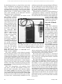
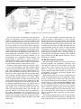
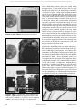
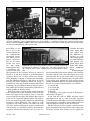
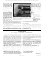
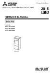
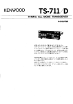
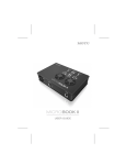
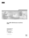
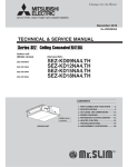
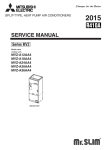
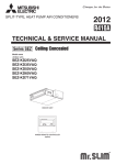
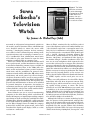
© 2001 National Association of Watch and Clock Collectors, Inc. Reproduction prohibited without written permission.
Figure 1. The Seiko
television wristwatch.
If you’re old enough
to recognize the RCA
“Indian head” test
pattern, then you
probably need glasses to see the screen.
Suwa
Seikosha’s
Television
Watch
by James A. Mahaffey (GA)
Shortly after the watch was invented, there was a
movement to add personal entertainment activities to
the watch’s practical functions. These embellishments
were designed strictly to amuse the owner while
retaining a timekeeping function. At first automata
were added, or little animated figures making small,
repetitive motions, such as swinging a hammer or waving a handkerchief. Next, subminiature music boxes
were added to play upon demand or upon the hour,
sometimes combined with an automata scene.
There was a limit to how much entertainment would
fit in a pocket watch, and the introduction of the wristwatch further limited the amount of space available for
non-timing machinery. Then, in the 1970s, fully electronic watch mechanisms became practical manufactured items, and the possibilities for personal entertainment seemed endless. AM radios, FM radios, music
synthesizers, and arcade games have all been incorporated into electronic watches, as well as many practical
auxiliary functions ranging from digital calculators to
global positioning system receivers. The ingenuity displayed in the miniaturization of devices to be included
in personal timepieces is impressive, but nothing in
amusement systems may quite surpass the bold design
of Suwa Seikosha, who put the world’s smallest directview television screen in a wristwatch.
Suwa Seikosha was one of several manufacturing
companies in the Seiko Group, which evolved from K.
Hattori & Company, an import/export trading company
specializing in clocks and watches, established in 1881.
In 1964, Suwa Seikosha established a solid reputation
in the clock business by building the automatic timers
for the Tokyo Olympic Games. In 1969, the company
perfected the world’s first quartz watch, and in 1973
introduced the liquid crystal display (LCD) as a time
read-out on a wristwatch.
February 2001
On June 16, 1982, Suwa Seikosha, in the Hotel
Okura in Tokyo, announced to the world the result of
years of development and several hundred million yen
—the television watch. Into a rectangular metal case,
76 by 143 by 18 millimeters and weighing 190 grams,
they had integrated a conventional LCD quartz watch
and a 1.2-inch (diagonal) television monitor. The
receiver fit in a pocket-sized box (74.5 by 125 by 19 millimeters, 140 grams), and conducted video signals to
the monitor though a flexible 6-conductor cable. The
user was to wear headphones which connected to the
receiver box and served as an antenna. The electronics
press was enchanted by the tiny TV picture, but was a
bit skeptical that this watch would sell enough units to
justify the estimated two trillion yen (about 10 million
dollars) necessary to tool up for production. The United
States was the targeted market, so the receiver was
built to decode National Television Standards Committee (NTSC) signals, and the retail price was set at
$495.
There were still problems to be solved. The display
looked dim, with only 20 to 30 percent contrast using
10 levels of gray, and the refresh rate was too low, causing rapidly moving pictures to smear. The linear
refresh-rate was 50 to 100 millimeters per second, and
it would have to be increased significantly before production. Shelf-life of the television screen module was
estimated to be seven years. The design was protected
by 10 basic patents and 150 related patents, and there
were still these kinks to be worked out.
Although the LCD was a mature technology by this
time, the process of ultra-miniaturized, animated display was on the frontier. The usual nematic LCD technology was too slow for this application, by orders of
magnitude. For this specific product Suwa Seikosha
developed a field effect (FE) very large scale integrated
(VLSI) circuit having 31,920 pixels, arranged in a 150
NAWCC BULLETIN
41
© 2001 National Association of Watch and Clock Collectors, Inc. Reproduction prohibited without written permission.
by 210 element matrix, on a single silicon wafer 30 by
problems encountered in mass-producing the TV-moni22 by 1.4 millimeters. On this chip was sufficient cirtor chip. Although the U.S. market did not live up to
cuitry to decode an analog NTSC signal and address
Seiko’s expectations, the TV watch did infiltrate poputhe digital LCD array, given a separate frame-timing
lar culture via Hollywood, appearing in the movies
signal. Refresh rate problems were resolved, and proDragnet, Wall Street and Octopussy.
duction began at a special factory in Fujimi, Japan,
Although there were plans to use this technology as
with watch assembly in the Shimauchi Precision
a springboard to making a wristwatch computer disInstruments factory in Matsumoto.
play terminal, introduction of such a device would wait
Timing of the announcement was critical, as Sir
for another decade. Suwa Seikosha and the Epson CorClive Sinclair of Sinclair
poration merged in 1985,
Research Ltd. was leakforming the Seiko Epson
ing information about his
Corporation. Sinclair’s TV
impending wristwatch TV
watch never appeared.
to be offered in the near
How the TV Watch
future. Production watchPerforms
es went on sale in early
1983, initially with one
The initial production
watch given to each Seiko
model is rare, and most
dealer. The earliest modexamples to be found are
els, designated T001the model T001-5019. A
5000, were sold in a silver
specimen is shown in Figcolored cardboard box,
ure 1, and Figure 2 shows
with a silver colored
the watch in relation to its
leather case to protect the
receiver module. This
receiver
module.
A
model closely resembles
mechanically
delicate
the prototype, except that
pair of stereo headphones
the name “Suwa Seikwas included, and the 6osha” on the prototype
conductor connecting cord
was changed to “Seiko,”
was packed separately.
and the legend “TELEVITwo AA-cells were providFigure 2. The TV watch with its receiver unit, connected
SION WATCH” across the
ed as an initial power
by a cable. The cable runs under your sleeve, with the
top was deleted from the
source. The only optional
receiver in an inside jacket pocket—a handy feature for
production model. The
accessory was an AC
church services, weddings, and other enforced events.
cable connector atop the
power adapter, part no.
case is bolstered on each
TD02. The earliest example of a T001-5000 I have
side by metal brackets, cast en-bloc with the case. This
found is serial no. 200646.
watch was sold in a gold colored cardboard box, with a
The initial production watch differed externally
sewn black leather case to hold the receiver.
from the prototype watch in a few cosmetic details. The
The watch portion of this system is a conventional
screen and watch display in the production model had
quartz watch with an LCD array, with time (12 and 24a black frame surrounding a satin chrome frame, with
hour), alarm, date, and stopwatch functions, controlled
watch button functions denoted in the black area,
by three push-buttons.
where the prototype was strictly cased in satin chrome.
The “liquid video display” (LVD) operates passively,
The cable connector, which had to be a robust design to
in that there is no illumination behind the screen, and
survive long in the hands of the consumer, was hidden
viewing light is incident. There are two advantages to
behind a satin chrome shroud in the prototype, but this
this design: it saves a great deal of power, and the
was reduced to a black plastic block in the initial proscreen can be seen in bright sunlight that would comduction model.
pletely wash out a conventional TV picture. The disadSales were disappointing, and production lasted
vantage is that the image is rather dim. The engineeronly about a year. The total number of watches proing problem that leads to this lack of brightness is that
duced is hard to determine, with estimates ranging
150 conductors must run over the top of the display to
from 2,000 to 20,000; non-consecutive serial numbers
supply the vertical address to pixels, and these printed
were used and provide no help in determining produc“wires” block the light. This is not noticeable in most
tion quantities. The company had hoped to build 13,000
LCD panels because so few picture elements are used,
but may have been unable to meet this quota. A limitbut in this case the panel is crowded with unusually
ing factor from a manufacturing standpoint was the
dense pixels.
42
NAWCC BULLETIN
February 2001
© 2001 National Association of Watch and Clock Collectors, Inc. Reproduction prohibited without written permission.
Figure 3. A page from the TV watch user’s manual.
Once you get used to the dimness of the television
image, the sharpness and the apparent richness of
detail are startling. You can easily read numbers and
written words flashed briefly across the screen, provided your eyes can focus close enough. The refresh rate of
the screen, which was a major worry for the engineers
who worked on the television watch, is not a noticeable
problem. If there is enough light to read the time on the
watch, then there is enough light to see the TV screen,
and it works well in the brightest sunlight. There is no
image distortion, “pincushion” effect, or problems of
vertical hold, because the imaging elements are in
fixed positions on a monolithic silicon substrate, and
picture-timing is provided by a master crystal-controlled oscillator, giving a precise 29.97 frames per second. Figure 3 is taken from the owner’s manual, showing the working features of this unusual watch.
Contrary to some rumors, there is no special “antenna wire” in the headphone cable. The television signal
is derived from the shield on the cable, and any eighthinch stereo headphone or 8-ohm single-channel earphone will work. The television receiver is able to stay
locked on a video signal under the unfavorable condition of having a flexible antenna constantly changing
orientation. The station selector is an analog adjustment, by thumb-wheel, over three switched ranges. By
using a mechanical station selector, rather than a digital electronic stepping device, the Seiko design is able
to withstand momentary signal loss without loss of
channel lock. Other contemporary subminiature television designs, such as the Casio TV-21, used the less
bulky, less expensive digital tuner and can suffer station loss. Motion of the tuning wheel is conducted to
the tuning potentiometer by an internal ring gear,
through one idler pinion. A worm-and-nut moves the
tuning cursor against a linear scale of the three television bands (low VHF, high VHF, and UHF) and an FM
radio band.
February 2001
On the radio frequency spectrum, FM radio lies
between channel 6 and channel 7 in the television
band, squeezed into only 16 megahertz of band width.
The TV watch receiver exploits the fact that it already
has an FM sound-tuner for the television function, and
it simply tunes sound on the FM radio band with the
picture blanked, giving the watch an extra function.
Performance of the radio function is disappointing,
probably because the TV tuner is built to extract as
much energy as possible from a TV signal using an
unusually wide intermediate frequency (IF) amplifier
stage. Closely spaced FM stations, therefore, tend to
bleed into one another.
TV Watch Service Procedures
The engineering estimate of a seven-year life for the
TV-screen module was pessimistic. Seventeen years
later, most TV watches are still working and are still
just as dim as they were the day they were bought.
There is a report of a TV watch that has operated 12
hours a day since 1983 in the window of a jewelry store
in Singapore, as its box and owner’s manual have
bleached in the sunlight.
Replacement parts are no longer available for this
watch, but fortunately many of its perishable components are generic and are still for sale. The watch chassis is shown in Figure 4 (front) and Figure 5 (back). The
watch battery is a silver oxide Maxell SR920W, and it
has no connection with the television function. Note
the six gold-plated fingers at the top of the chassis.
These connect, by simple tension, to the flush-mounted, weatherproof pins of the television connector at the
top of the watch. The back presses on, and although
there is no implied water resistance, it is fitted with a
rubber seal.
Correctable problems occur in the receiver module,
shown partially dismantled in Figure 6. Although this
unit is about the size of a pocket radio, it is built with
NAWCC BULLETIN
43
© 2001 National Association of Watch and Clock Collectors, Inc. Reproduction prohibited without written permission.
Figures 4 and 5. Above, front of watch mechanism.
Below, the back.
more watchmaking influence than with pocket radio
design practices, as it is built in layers, and it is put
together with 1mm screws. A 2mm Phillips screwdriver will take it apart, starting with two flush-mounted
screws on the bottom, holding the metal front cover.
The cover then slides off. The side cover, having the TV
cable socket, comes off next, with one screw on the bottom. It is connected to the electronic chassis by way of
a thin mylar ribbon cable, terminated in gold-plated
spears. Be especially careful with this ribbon, as it can
develop hairline cracks if overly exercised. Two screws
in front hold the metal top cover, which will lift off with
switch knobs attached. The two plastic covers for the
electronic section are held together with long 1mm
Phillips screws, and some finesse is necessary to separate the mechanism from the backplate. Two layers of
printed wiring boards are held together by two mylar
ribbon bridges. If necessary, the two boards may be separated using 0.03-inch solder wick and a 25-watt iron.
A 3-volt power supply attached to the remaining battery contacts, or through the external power jack, will
run the television for bench work.
There are four adjustments for the receiver, and the
maintenance adjustment points are shown in Figure 7.
The adjustment point shown on the left side of the picture is a 260-degree potentiometer, and it changes the
tuner offset, for the purpose of lining up the tuning cursor with the channel numbers. The point in the middle
is the video gain, or contrast, and it is also a 260-degree
potentiometer. Both of these adjustment points are
accessible with the metal front cover off, through holes
in the plastic frontplate. Use a 2mm bladed screwdriver. The video offset, or brightness, is adjustable by
hand, with a thumb-operated knob on the back of the
chassis. The third adjustment point shown in the
photo, on the right, is the power converter frequency, or
converted voltage level. Although a special tool is used
for this adjustment, this subminiature potentiometer
can be turned easily with a 1mm bladed screwdriver.
Figure 6, above. The television receiver, broken down.
Figure 7, right. Maintenance adjustment points at the
ends of the screwdrivers. On the left is the tuning offset,
middle is the contrast, and right is the power level.
44
NAWCC BULLETIN
February 2001
© 2001 National Association of Watch and Clock Collectors, Inc. Reproduction prohibited without written permission.
Figure 8, left. The top front of the electronics chassis, showing an electrolytic capacitor position (in white box) at center frame. Although it seems trapped between the circuit boards, it is possible to replace this capacitor without separating the boards. Figure 9, right. Another tight capacitor location (in white box), nested between the volume control,
the contrast potentiometer, and the tuner slide.
Components
cuit
b o a r d s.
most likely to fail
Unsolder the failed
due to age in the
units using 0.03receiver module are
inch solder wick.
the subminiature
The KS-Series caelectrolytic capacipacitors are availtors. There are five
able in unit quanticritical capacitors.
ties from Digi-Key,
Two are 47 micro701 Brooke Ave.
farads, and three
South, Thief River
Figure 10. Side view of the electronics chassis, showing another capare 100 microFalls, MN 56701tive electrolytic capacitor (in white box). The metal structure on the
farads. All five have
0677, 1-800-344right encloses the TV tuner, shielding it from electromagnetic interfera breakdown volt4539.
ence.
age of 6.3 volts, and
A convenient port
their positions in the electronic chassis are shown in
for measuring the three critical voltages and seeing the
Figures 8, 9, and 10. A shorted or opened electrolytic
television signals is the end of the signal cord, at the
capacitor affects one of three critical DC voltages,
connector that fits on the watch. There are six goldeither dropping it slightly or allowing AC contaminaplated contacts on the connector, plus one gold contact
tion. The slightest skewing of a DC voltage to the TV
in the anchor point opposite the cord, used for chassis
monitor will either completely blank the screen or
ground. Numbering the line of contacts beginning with
scramble the image into roughly horizontal bars. When
the one nearest the cord, the signals are as follows:
diagnosing voltage problems, check the battery connec1) 8.9 volts DC.
tion paddles for corrosion, and check the soldered bases
2) 13.2 volts DC.
of these paddles for hairline cracks.
3) 4.1 volts DC.
Failed capacitors can be found by visual inspection
4) Ground.
with a loupe. As the caustic electrolyte leaks out it com5) Low-going 5-volt pulses, spaced at 60 microsecbines with copper in the wiring to form a waxy subonds (frame-rate pulse).
stance, bright green in color. The slightest hint of green
6) 8.0 volts DC, with an NTSC television signal
at the base of a capacitor indicates failure. The replacesuperimposed on top, 1.5 volts in height, repeating
ments are special, low-profile, radial-lead units built by
every 60 microseconds. The 8.0 volts is the brightness
Panasonic, called “KS-Series.” The height of a KS
level, and it may vary widely among different watches
capacitor is only 5mm, and they are built to fit in the
and with different settings on the receiver back.
very close quarters. Although it requires careful work
The DC voltages can be read with a volt-ohm meter.
with tweezers, it is possible to replace all electrolytic
A five percent deviation up or down will scramble the
capacitors without separating the two receiver cirTV image, and the three voltages can be adjusted in
February 2001
NAWCC BULLETIN
45
© 2001 National Association of Watch and Clock Collectors, Inc. Reproduction prohibited without written permission.
site sides of the socket,
concert by turning the conunder tension from the
verted voltage level control,
structure of the plug. For
as mentioned above. A sinsome reason the left depresgle voltage dropout indision was made less deep in
cates a possible electrolytic
late watches, and the cable
capacitor failure, and these
snaps off too easily. This
values should be confirmed
depression can be modified
on an oscilloscope, as there
with a 1.5mm drill or endshould be a zero ripple commill. Correct depth is
ponent. In one case, I found
0.5mm.
the voltage on pin 2 absent,
and I spent an interesting
References
time tracing it through both
1 “Armbanduhr mit Fernse
circuit boards until I lost it
her,” Das Electron Interas the copper trace disapnational, No. 8-9, pp.221Figure 11. Two TV watch cases. The top case,
peared under a tiny blob of
2, 1982.
SN330135, has a well formed dimple for the signal
glue. The glue was used to
2 “Wrist Watching! (Wristconnector, while the bottom case, SN351357, has a
immobilize an open coil.
watch TV),” Middle East
dimple that is too shallow.
Under the glue blob I
Electronics, Vol. 7, No. 3,
found that the very thin
March 1984, p.41.
3 Seiko TV Watch T001/Instruction Manual, 1983.
copper trace had corroded through, probably due to a
microscopic ball of moisture getting trapped just as the
About the Author
glue was applied. I bridged the gap with an exceedingJames A. Mahaffey has a BS in Physics, an MS and
ly thin strand of copper wire.
a PhD in Nuclear Engineering, and is Director of
One slight but notable change occurred in the case
Advanced Research at Nanoventions in Roswell, GA.
design of the T001-5019 watch, as shown in Figure 11.
He is contributing editor to the Mercedes Benz Club of
There is a slight depression on either side of the cable
America magazine, The Star, and he wears a Breitling
socket, intended to secure the cable plug so it won’t pop
Navitimer 806 every day.
off. Fixed steel balls fall into the depressions on oppo-
IN MEMORIAM
Donald G. Lance (1915-2000) • FNAWCC 1206
Donald G. Lance, a member of NAWCC and Great
Lakes Chapter 6 since 1952, died September 17, 2000. He
was extremely proud of his NAWCC membership and
ordered his 45-year pin the first time it became available.
At one time he had more than 200 clocks. His field of
interest was primarily American wood movement clocks,
and he became an authority on them and an expert restorer of both movements and cases. He presented several
chapter programs on this subject. He boasted that he
could take apart and put back together a wood movement
blindfolded, and had been seen doing it.
He served the Great Lakes chapter as treasurer, as
NAWCC Annual Meeting Reception Chairman, and as
president in 1961-63. He also served on the national membership committee. He taught classes on antique clock
repair at Macomb Community College, and as a result of
his sharing his extensive knowledge and encouraging several people to join the NAWCC, he was named a Fellow in
1971 and was given the Great Lakes Chapter Outstanding Member Award by President Owen Burt in 1995.
Don was a great believer in reading. He owned almost
every clock book ever published. Even in his 85th year, he
46
was still in correspondence with other NAWCC members,
researching clock problems. He also believed in having
fun in life, and when he conducted the chapter auctions
for many years he made them hilarious events, as well as
profitable for the chapter.
Don loved antique clocks, but he loved the collectors of
antique clocks even more. He had friends from many
walks of life, but among his most treasured friendships
were those with several special fellow clock collectors. He
always had great praise for the organization which
brought them together—the National Association of
Watch and Clock Collectors.
One of his favorite poems, author unknown, was:
“The clock of life is wound but once
And no one has the power
To tell just when the hands will stop
At late or early hour.
Now is the only time you own
Live, love, toil with a will.
Place no faith in tomorrow for
The clock may then be still.”
Mrs. Lois Lance
NAWCC BULLETIN
February 2001