1
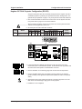
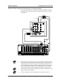
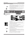
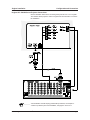
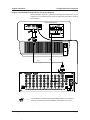
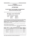
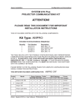
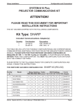
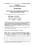
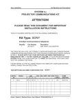
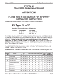
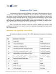
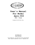
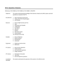
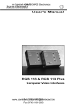
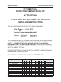
Hughes Installation
Configuration and Connections
SYSTEM 8/10 Plus
PROJECTOR COMMUNICATIONS KIT
ATTENTION!
PLEASE READ THIS DOCUMENT FOR IMPORTANT
INSTALLATION INSTRUCTIONS
THIS KIT HAS BEEN SHIPPED WITH THE FOLLOWING COMPONENTS:
Kit Type: HUGHES
Included Communications Adapter(s):
Quantity
1
Part Number
26-467-01
Description
ADP, UNV, “A”
THE TABLE BELOW LISTS THE POSSIBLE CONFIGURATION(S) AND CORRESPONDING
COMMUNICATIONS ADAPTER(S) FOR YOUR PROJECTOR MANUFACTURER’S VARIOUS
MODELS. PLEASE NOTE THAT YOUR SWITCHER HAS BEEN CONFIGURED AS
INDICATED BY THE “✔” IN THE “Config as” COLUMN. IF YOUR PROJECTOR MODEL
DIFFERS FROM THIS CONFIGURATION, YOU MUST RECONFIGURE YOUR SWITCHER
WITH THE CORRECT SETTINGS.
PLEASE REFER TO THE FOLLOWING PAGES FOR COMPLETE CONFIGURATION AND
SIGNAL CONNECTION INSTRUCTIONS.
THIS SWITCHER HAS BEEN CONFIGURED FOR:
Config
as
✔
Model
HUGHES/JVC
Rotary Switches Cable
SW15 Settings
Comm
RS1 RS2 RS3 RS4 J2/J3 1 2 3 4 5 6 7 8 9 10 Adapter
Hughes-JVC
0
0
6
5
J2
↓ ↓ ↑ ↓ ↑ ↓ ↓ ↓ ↑ ↓ 26-467-01
Hughes DILA
0
0
F
8
J2
↓ ↓ ↑ ↓ ↑ ↓ ↓ ↓ ↑ ↓ 26-467-01
Extron • System 8/10 PLUS • User’s Manual • P/N 68-412-01 Rev. A
Hughes Installation
Configuration and Connections
Hughes-JVC DILA Projector Configuration (RS-232)
Verify that the System 8/10 Plus is already configured for the Hughes-JVC DILA
G1000/G10 projector by following the procedure and switch settings below. The
general setup is explained on page 3-4 of your System 8/10 Plus User’s Manual.
1. Use a small screwdriver to remove the access cover from the System 8/10 Plus
front panel. Refer to page 3-3 of the User’s Manual.
_______________ Before changing anything, remove the AC power cord to the System 8/10 Plus
and also turn the projector’s power OFF.
2. Set the System 8/10 Plus switches as follows:
Config
Model
Rotary Switches Cable
as
SW15 Settings
RS1 RS2 RS3 RS4 J2/J3
Hughes-JVC DILA
0
0
F
8
1 2
3
4
5
6
↓ ↓ ↑ ↓ ↑ ↓
J2
Comm
7 8
9 10
↓ ↓ ↑ ↓
4
Adapter
26-467-01
¯
ON
1
2
3
4
5
6
7
8
9
10
SW15 DIP Switch
RS2
RS3
RS5 RS2 RS1
RS1
RS3 RS4
RS4
Configured For:
RS-232
3. Locate the switcher’s Address DIP switches on the rear panel, lower right.
Unless this is part of a master/slave system, set #3 and #5 to the up position and
the others in the down position. See illustration on the left.
4. Use the illustration on the following page and continue with the steps below.
5. Connect the BNC cables from the System 8/10 Plus outputs to the projector
inputs according to the application requirements (RGBS, S-Video or Composite
Video).
6. Apply Main Power to the System 8/10 Plus by connecting the power cord. The
Main Power LED should light. Apply power to the projector.
7. Installation is now completed.
Extron • System 8/10 PLUS • User’s Manual • P/N 68-412-01 Rev. A
Page 1
Hughes Installation
Configuration and Connections
System 8/10 Plus to Hughes-JVC DILA Projector Connections (RS-232)
Use the illustration below as a guide when connecting the System 8/10 Plus to
the Hughes-JVC DILA projector. Refer to projector documentation to continue
the installation.
S-Video Adapter
COMPUTER IN-2
Y/C
AV IN
VIDEO
AUDIO
PC
COMPUTER IN-2
AUDIO
AUDIO
R
9-Pin Female
G
H/Cs
B
V
COMPUTER
OUT
L
Y
R
PB /B-Y
PR /R-Y
CONTROL
REMOTE
AUDIO OUT
RS - 232C
CommAdapter
26-467-01
Composite
Video
RGBHV 5 BNC
15-Pin
Male
S-Video
________ When RS-232 control of the projector is used, the projector’s IR remote can be
used. However, because the projector’s IR remote does not communicate with
the System 8/10 Plus switcher, the projector and switcher can become out-ofsync if the projector’s IR remote is used to change the projector’s input, picture
mute or power settings. Should this occur, press the power, mute or channel
buttons on the switcher to allow the projector and switcher to resynchronize.
________ If the installation includes looping (master/slave) switchers, see Chapter 5 of the
System 8/10 Plus User’s Manual.
________ If Video Loop Back is part of the installation, refer to pages 2-10 and 2-11.
Extron • System 8/10 PLUS • User’s Manual • P/N 68-412-01 Rev. A
Page 2
Hughes Installation
Configuration and Connections
Hughes/JVC Projector Configuration
Check to see if the System 8/10 PLUS is already configured for the Hughes/JVC
projector. The general setup is explained on page 3-4 and the switch settings for
the Hughes/JVC projector are repeated below.
1. Use a small screwdriver to remove the access cover from the System 8/10 PLUS
front panel. See bottom of page 3-3. The label on the back of the access cover
also has the configuration information.
__________ Before changing anything, remove the AC power cord to the System 8/10 PLUS
to verify that the main power is OFF; also turn the projector power OFF.
2. Set the switches as follows:
Config
Model
as
Rotary Switches Cable
RS1 RS2 RS3 RS4 J2/J3
Hughes-JVC
0
0
6
5
J2
SW15 Settings
1 2
3
4
5
6
Comm
7 8
↓ ↓ ↑ ↓ ↑ ↓
9 10
↓ ↓ ↑ ↓
4
Adapter
26-467-01
¯
ON
_ RS5 is for RGB switching
delay. See page 3-4 for
more information on switch
functions.
1
2
3
4
5
6
7
8
9
10
SW15 DIP Switch
RS2
RS3
RS5 RS2 RS1
RS4
RS1
RS3 RS4
Configured For:
RS-232
3. Use a grease pencil (or other rub-off marker) to mark the space on the label next
to “Hughes/JVC”.
4. Locate the switcher’s Address DIP switches on the rear panel, lower right.
Unless this is part of a master/slave system, set #3 and #5 to the up position and
the others down. See picture to the left.
Use the illustration on the facing page to do the following steps.
5. Connect the Comm Adapter’s 9-pin female connector to the 9-pin male “Control
Out” connector on the rear panel of the projector.
6. Connect the CC-50' (or CC-100') cable from the 9-pin male connector of the
Comm Adapter to the 15-pin HD “Projector Control” port located on the rear
panel of the System 8/10 PLUS.
______ Secure the screws on all D connectors.
7. Connect the BNC (RGBS) cables from the System 8/10 P LUS outputs to the
Hughes/JVC projector inputs according to the application requirements. (RGBS,
S-Video and/or Composite Video)
8. Apply Main Power to the System 8/10 PLUS by connecting the power cord. The
Main Power LED should light. Apply power to the projector.
9. Return System 8/10 PLUS and projector to normal operation.
Extron • System 8/10 PLUS • User’s Manual • P/N 68-412-01 Rev. A
Page 3
Hughes Installation
Configuration and Connections
Hughes/JVC 300/400 Series Projector Connections
Use the illustration below when connecting the System 8/10 PLUS to a Hughes/
JVC 300/400 Series projector. Refer to Hughes/JVC documentation to continue
the installation.
________ If the installation includes looping (master/slave) switchers, see Chapter 5.
If Video Loop Back is part of the installation, see pages 2-10 and 2-11.
Extron • System 8/10 PLUS • User’s Manual • P/N 68-412-01 Rev. A
Page 4
Hughes Installation
Configuration and Connections
Hughes / JVC Model HJT 100/200 Series Connection Diagram
Use the illustration below as a guide when connecting the System 8/10 PLUS to a
Hughes/JVC HJT 100/200 projector. Refer to Hughes documentation to continue
the installation.
Hughes HJT 200 Projector
Terminal In
Port A
Control Out
(Port B)
3, 4,
or 5
BNC
Cable
CC 50'
________ If the installation includes looping (master/slave) switchers, see Chapter 5.
If Video Loop Back is part of the installation, see pages 2-10 and 2-11.
Extron • System 8/10 PLUS • User’s Manual • P/N 68-412-01 Rev. A
Page 5
Hughes Installation
Configuration and Connections
Special Instructions for the HJT Model 100/200 Series
The projector documentation provides instructions on how to set up and
configure the Model 100/200 Series Projector for proper operation with the
System 8/10 PLUS.
The baud rate for the Extron switchers is 19200. Since Port A is locked to a
baud rate of 9600, Port B should be used for Extron Switchers. The projector
port assignment must be selected and the VIC channel assignment must be
edited for a switcher. Following is a description of the HJT 100/200 Series Menu.
To select the Baud Rate from the Projector:
1. Go to Main Menu, select #7, System, then #4, Comm. Setup.
2. From the Comm. Setup menu, select Port B Speed.
3. From the Speed selection list, select 19200.
4. Press Escape to go back to the Comm. Setup level.
To set the projector port assignment from the Projector:
1. From the Comm. Setup menu, select Port B Device.
2. From the Device type list, select #3, Video Switcher.
3. Turn power off at the remote control.
4. Wait until the Arc Lamp fans have stopped running and provide a system cold
boot by toggling the circuit breaker on the projector rear panel to Off, then back
to On.
To edit the VIC channel assignment from the Projector:
(see the Model 100/200 User’s Guide, Section 5.3.1 for more information on
editing):
1. From the Channels list, select the channel that the switcher will be assigned
to.
2. Press Mode. This is a toggle key that brings up a submenu for editing. (Press
Mode again to remove the submenu.)
3. Select Edit from the submenu and press Enter.
4. Use the right arrow key to toggle over to the third VIC column.
5. Press Enter and use the up/down arrow keys to select the current switcher
channel number. Press Enter when the current switcher channel number is
shown.
6. Press Escape to exit the Edit mode.
Extron • System 8/10 PLUS • User’s Manual • P/N 68-412-01 Rev. A
Page 6