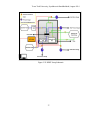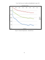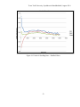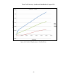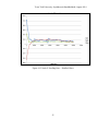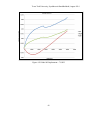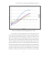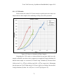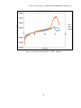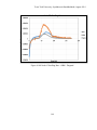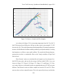
1
Investigation of Effects of Temperature and Swelling on Wellbore Stability in Unconventional Reservoirs by Seyedhossein Emadibaladehi, B.Sc., MSc. A Dissertation In Petroleum Engineering Submitted to the Graduate Faculty of Texas Tech University in Partial Fulfillment of the Requirements for the Degree of DOCTOR OF PHILOSOPHY Approved Dr. Mohamed Y. Soliman Chair of Committee Dr. Robello Samuel Dr. Lloyd R. Heinze Dr. James Sheng Mark A. Sheridan Dean of the Graduate School August, 2014 Copyright 2014, Seyedhossein Emadibaladehi Texas Tech University, Seyedhossein Emadibaladehi, August 2014 ACKNOWLEDGMENTS I would like to express the deepest appreciation to my committee chair, Professor Mohamed Y. Soliman, who has been a tremendous mentor for me. I would like to thank you for encouraging me to perform my research and for giving me the opportunity to develop a grasp understanding of research. Your advice on research as well as on my professional career has been invaluable. I would like to thank my committee members, Dr. Robello Samuel, Dr. Lloyd R. Heinze, and Dr. James Sheng for their support and for serving as my committee members even at hardship. I also want to appreciate all your brilliant comments and guidance. I received an extraordinary help form Mr. Shannon Hutchison and Mr. Joseph McInerney with laboratory tests and experimental aspects of this research. The help and support of the department of Petroleum Engineering staff is highly appreciated, you foster the bond of cooperation and atmosphere that accelerates progress and productivity. A special thanks to the present and past chairs of the department who provided the leadership and stability required for research throughout my work on this research. A special appreciation to my dear family. Words cannot express how grateful I am to my mother, Safoura, and father, Reza, for all the sacrifices you have done for me to be where I am now and all your prayer which sustained me thus far. Special thanks to my siblings Zahra, Fatemeh, Mohammad, and Hamed for all your support. I would also like to thank all of my friends who helped me to strive towards my goal. Finally and most reverently, I thank God, the giver of life, wisdom, his blessings, grace, mercies, and inspiration which are numerous, without him and his help, this work would not be done. ii Texas Tech University, Seyedhossein Emadibaladehi, August 2014 TABLE OF CONTENTS 1. ACKNOWLEDGMENTS ........................................................................................ ii 2. ABSTRACT...............................................................................................................v 3. LIST OF TABLES .................................................................................................. vi 4. LIST OF FIGURES ............................................................................................... vii 5. 1. INTRODUCTION .................................................................................................1 1.1. Differences between Common Shale and Shale Oil Samples’ Properties...........2 1.1.1. Cation Exchange Capacity (CEC)......................................................................... 2 1.1.2. Swelling Properties .............................................................................................. 3 1.1.3. Osmosis in Shale Formations ............................................................................... 3 1.1.4. Mineralogy ........................................................................................................... 5 1.1.5. Pore Fluid ............................................................................................................ 5 1.2. Research Objectives .........................................................................................6 1.3. Research Methodology .....................................................................................6 6. 2. LITERATURE REVIEW .............................................................................................8 2.1. Swelling Properties...........................................................................................8 2.2. Effects of Temperature .....................................................................................8 7. 3. EXPERIMENTAL SETUP: EQUIPMENTS AND PROCEDURES ................. 10 3.1. Swelling Test Apparatus ................................................................................. 10 3.1.1. Pre-Wired Strain Gauge ..................................................................................... 10 3.1.2. Epoxy ................................................................................................................ 11 3.1.3. M- Prep Conditioner and Neutralizer .................................................................. 12 3.1.4. Alcohol ............................................................................................................... 12 3.1.5. Super Glue ........................................................................................................ 13 3.1.6. Silicone .............................................................................................................. 14 3.1.7. V-Shay Data Acquisition System ........................................................................ 15 3.1.8. Mechanical Testing and Sensing Solutions (MTS) Machine ................................ 15 3.1.9. Linearly Variable Displacement Transducer (LVDT)............................................ 16 3.2. Swelling Test Procedure ................................................................................. 17 3.3. High Pressure High Temperature (HPHT) Test Apparatus .............................. 19 3.3.1. Design of the HPHT Equipment.......................................................................... 19 3.3.2. HPHT Setup Components and Specifications ..................................................... 20 3.3.3. Vacuum Pump ................................................................................................... 24 3.3.4. Data Acquisition System (DAQ).......................................................................... 28 3.4. HPHT Test Procedure..................................................................................... 38 8. 4. SWELLING EXPERIMENTS: RESULTS AND DISCUSSION OF RESULTS .......................................................................................................................... 40 4.1. Experimental Results – Actual Eagle Ford Core Samples ............................... 40 4.1.1. Core Characterization ........................................................................................ 40 4.1.2. Swelling Test Results – Distilled Water............................................................... 46 4.1.3. Swelling Test Results – 7% KCl ......................................................................... 59 4.1.4. UCS Results ...................................................................................................... 73 4.2. Experimental Results – Commercial Eagle Ford Core Samples ...................... 75 iii Texas Tech University, Seyedhossein Emadibaladehi, August 2014 4.2.1. Core Characterization ........................................................................................ 75 4.2.2. Swelling Test Results – 7% KCl ......................................................................... 78 9. 5. HPHT EXPERIMENTS: RESULTS AND DISCUSSION OF RESULTS ....... 153 5.1. Core Characterization ................................................................................... 153 5.2. HPHT Experimental Condition ..................................................................... 154 5.3. HPHT Experimental Results ......................................................................... 180 10. 6. CONCLUSIONS AND RECOMMENDATIONS .......................................................... 193 6.1. Conclusions .................................................................................................. 193 6.2. Recommendations ........................................................................................ 194 11. NOMENCLATURE ............................................................................................ 196 12. BIBLIOGRAPHY ..................................................................................................... 198 13. VITA .................................................................................................................... 201 iv Texas Tech University, Seyedhossein Emadibaladehi, August 2014 ABSTRACT The industry is still at the beginning of the learning curve for shale oil drilling operations; however, many shale-oil wells have been drilled in recent years. Drilling through shale-oil formations may very problematic and imposes significant costs to the operators owing to wellbore-stability problems. These problems include, but are not limited to, tight holes, stuck pipe, fishing, sidetracking, and well abandonment. To more efficiently and effectively drill through these formations, we should better understand their properties. Few experiments have been performed on shale-oil samples to better understand their properties. Most experiments conducted thus far were performed on common shale core samples, which are significantly different from shale oil samples. In this study, we first determined the mineralogy of shale-oil core samples from the Eagle Ford field and then investigated the swelling properties and Cation Exchange Capacity (CEC) of the core samples in the laboratory. Experiments have been conducted with the samples partially submerged in distilled water, potassium-chloride (KCl) brine and Oil-Based Mud (OBM). Several experiments have been performed using strain gages to measure lateral, axial, and diagonal swelling in both submerged and non-submerged areas. To simulate actual well conditions a High Pressure, High Temperature (HPHT) core holder was used to apply different axial and radial confining stresses, equivalent formation pore pressure, and drilling fluid wellbore pressure. The experiments were conducted under elevated temperatures to better mimic real drilling operations. Saturated shale oil core samples from the Eagle Ford field were tested under various temperatures including reservoir temperature. I also performed Unconfined Compressive Strength (UCS) tests were performed to investigate the effect of temperature on the compressive strength of the core samples. The experimental setup was modified to accommodate five Linearly Variable Displacement Transducers (LVDTs) to measure Young’s Modulus (E) and Poisson’s ratio (ν). Various experiments were run to quantify the effect of temperature on the rock compressive strength, E, and ν. Experiments have shown a distinct change in the mechanical properties of the rock. v Texas Tech University, Seyedhossein Emadibaladehi, August 2014 LIST OF TABLES Table 1-1 CEC of Major Clay Minerals and sand (Stephens et. al. 2009) .....................2 Table 1-2 Mineralogy for a core sample from Shale Oil Eagle Ford reservoir...............................................................................................5 Table 1-3 Mineralogy of a core sample from Shale Gas Eagle Ford reservoir...............................................................................................6 Table 3-1 C2A-06-250WW-350 Strain Gauge Properties .......................................... 10 Table 4-1 Mineralogy for a core sample from Shale Oil Eagle Ford reservoir............................................................................................. 41 Table 4-2 Sample Specifications ............................................................................... 41 Table 5-1 Sample Specifications ............................................................................. 154 Table 5-2 HPHT Testing Parameters ....................................................................... 155 Table 5-3 Measured Parameters .............................................................................. 192 vi Texas Tech University, Seyedhossein Emadibaladehi, August 2014 LIST OF FIGURES Figure 3-1 Stacked rosette strain gauge ..................................................................... 11 Figure 3-2 M-Bond Type 10...................................................................................... 11 Figure 3-3 M-Bond Adhesive Resin Type AE ........................................................... 11 Figure 3-4 M-Prep Neutralizer .................................................................................. 12 Figure 3-5 M- Prep Conditioner ................................................................................ 12 Figure 3-6 Alcohol .................................................................................................... 13 Figure 3-7 M-Bond 200 Adhesive ............................................................................. 14 Figure 3-8 Silicon ..................................................................................................... 14 Figure 3-9 V-Shay Data Acquisition System ............................................................. 15 Figure 3-10 MTS Machine ........................................................................................ 16 Figure 3-11 LVDT .................................................................................................... 16 Figure 3-12 Thelco Laboratory Oven ........................................................................ 21 Figure 3-13 Phoenix Precision Instruments Core Holder ........................................... 22 Figure 3-14 Hydraulic Pump ..................................................................................... 23 Figure 3-15 Ametek Chandler Positive Displacement Quizix Pumps ......................... 24 Figure 3-16 Welch vacuum pumps ............................................................................ 25 Figure 3-17 Floating Piston Accumulators used in HPHT Setup ................................ 26 Figure 3-18 Nitrogen Cylinder used in HPHT Setup.................................................. 27 Figure 3-19 Autoclave Engineering Incorporation valve ............................................ 28 Figure 3-20 cFP-2200, its modules and power supply ............................................... 30 Figure 3-21 HEISE Pressure Transducer ................................................................... 31 Figure 3-22 EXTECH Instruments power supply ...................................................... 32 Figure 3-23 LabView Front Panel ............................................................................. 35 Figure 3-24 LabView Block Diagram ....................................................................... 36 Figure 3-25 HPHT Setup Schematic.......................................................................... 37 Figure 4-1 Strain gauge locations .............................................................................. 42 Figure 4-2 Sample prepared for swelling test............................................................. 42 Figure 4-3 Environmental chamber ........................................................................... 43 Figure 4-4 MTS machine and LVDT’s set up ............................................................ 44 vii Texas Tech University, Seyedhossein Emadibaladehi, August 2014 Figure 4-5 On the left is the placement of nodes for the specimen submerged in 7%KCl fluid, on the right is the location of nodes for the sample submerged in distilled water.......................... 45 Figure 4-6 Node 01 Displacement – Distilled Water.................................................. 46 Figure 4-7 Node 01 Swelling Rate – Distilled Water ................................................. 47 Figure 4-8 Node 02 Displacement – Distilled Water.................................................. 48 Figure 4-9 Node 02 Swelling Rate – Distilled Water ................................................. 49 Figure 4-10 Node 03 Displacement – Distilled Water ................................................ 50 Figure 4-11 Node 03 Swelling Rate – Distilled Water ............................................... 51 Figure 4-12 Node 04 Displacement – Distilled Water ................................................ 52 Figure 4-13 Node 04 Swelling Rate – Distilled Water ............................................... 53 Figure 4-14 Node 05 Displacement – Distilled Water ................................................ 54 Figure 4-15 Node 05 Swelling Rate – Distilled Water ............................................... 55 Figure 4-16 Node 06 Displacement – Distilled Water ................................................ 56 Figure 4-17 Node 06 Swelling Rate – Distilled Water ............................................... 57 Figure 4-18 Strain Ratios for all Four Submerged Nodes – Distilled Water ................................................................................................. 58 Figure 4-19 Node 01 Displacement – 7% KCl ........................................................... 59 Figure 4-20 Node 01 Swelling Rate – 7% KCl .......................................................... 60 Figure 4-21 Node 02 Displacement – 7% KCl ........................................................... 61 Figure 4-22 Node 02 Swelling Rate – 7% KCl .......................................................... 62 Figure 4-23 Node 03 Displacement – 7% KCl ........................................................... 63 Figure 4-24 Node 03 Swelling Rate – 7% KCl .......................................................... 64 Figure 4-25 Node 04 Displacement – 7% KCl ........................................................... 65 Figure 4-26 Node 04 Swelling Rate – 7% KCl .......................................................... 66 Figure 4-27 Node 05 Displacement – 7% KCl ........................................................... 67 Figure 4-28 Node 05 Swelling Rate – 7% KCl .......................................................... 68 Figure 4-29 Node 06 Displacement – 7% KCl ........................................................... 69 Figure 4-30 Node 06 Swelling Rate – 7% KCl .......................................................... 70 Figure 4-31 Strain Ratios for all Four Submerged Nodes – 7% KCl .......................... 71 Figure 4-32 Stress vs. Strain for all Three Samples ................................................... 73 viii Texas Tech University, Seyedhossein Emadibaladehi, August 2014 Figure 4-33 On the left, intact sample after UCS test, in the middle, distilled water sample after UCS test, on the right, 7% KCl sample after UCS test. ................................................................ 74 Figure 4-34 Sample prepared for swelling test - Diagonal to bedding ........................ 76 Figure 4-35 Strain gage locations .............................................................................. 76 Figure 4-36 Locations of nodes for the specimens ..................................................... 77 Figure 4-37 Node 01 Displacement - 7% KCl - Perpendicular ................................... 78 Figure 4-38 Node 01 Swelling Rate - 7% KCl - Perpendicular .................................. 79 Figure 4-39 Node 02 Displacement - 7% KCl - Perpendicular ................................... 80 Figure 4-40 Node 02 Swelling Rate - 7% KCl - Perpendicular .................................. 81 Figure 4-41 Node 03 Displacement - 7% KCl - Perpendicular ................................... 82 Figure 4-42 Node 03 Swelling Rate - 7% KCl - Perpendicular .................................. 83 Figure 4-43 Node 04 Displacement - 7% KCl - Perpendicular ................................... 84 Figure 4-44 Node 04 Swelling Rate - 7% KCl - Perpendicular .................................. 85 Figure 4-45 Node 05 Displacement - 7% KCl - Perpendicular ................................... 86 Figure 4-46 Node 05 Swelling Rate - 7% KCl - Perpendicular .................................. 87 Figure 4-47 Node 06 Displacement - 7% KCl - Perpendicular ................................... 88 Figure 4-48 Node 06 Swelling Rate - 7% KCl - Perpendicular .................................. 89 Figure 4-49 Swelling Ratio - 7% KCl - Perpendicular ............................................... 90 Figure 4-50 Node 01 Displacement - 7% KCl - Parallel ............................................ 91 Figure 4-51 Node 01 Swelling rate - 7% KCl - Parallel ............................................. 92 Figure 4-52 Node 02 Displacement - 7% KCl - Parallel ............................................ 93 Figure 4-53 Node 02 Swelling rate - 7% KCl - Parallel ............................................. 94 Figure 4-54 Node 03 Displacement - 7% KCl - Parallel ............................................ 95 Figure 4-55 Node 03 Swelling rate - 7% KCl - Parallel ............................................. 96 Figure 4-56 Node 04 Displacement - 7% KCl - Parallel ............................................ 97 Figure 4-57 Node 04 Swelling rate - 7% KCl - Parallel ............................................. 98 Figure 4-58 Node 05 Displacement - 7% KCl - Parallel ............................................ 99 Figure 4-59 Node 05 Swelling rate - 7% KCl - Parallel ........................................... 100 Figure 4-60 Node 06 Displacement - 7% KCl - Parallel .......................................... 101 Figure 4-61 Node 06 Swelling rate - 7% KCl - Parallel ........................................... 102 ix Texas Tech University, Seyedhossein Emadibaladehi, August 2014 Figure 4-62 Node 01 Displacement - 7% KCl - Diagonal ........................................ 103 Figure 4-63 Node 01 Swelling rate - 7% KCl - Diagonal ......................................... 104 Figure 4-64 Node 02 Displacement - 7% KCl - Diagonal ........................................ 105 Figure 4-65 Node 02 Swelling rate - 7% KCl - Diagonal ......................................... 106 Figure 4-66 Node 03 Displacement - 7% KCl - Diagonal ........................................ 107 Figure 4-67 Node 03 Swelling rate - 7% KCl - Diagonal ......................................... 108 Figure 4-68 Node 04 Displacement - 7% KCl - Diagonal ........................................ 109 Figure 4-69 Node 04 Swelling rate - 7% KCl - Diagonal ......................................... 110 Figure 4-70 Node 05 Displacement - 7% KCl - Diagonal ........................................ 111 Figure 4-71 Node 05 Swelling rate - 7% KCl - Diagonal ......................................... 112 Figure 4-72 Node 06 Displacement - 7% KCl - Diagonal ........................................ 113 Figure 4-73 Node 06 Swelling rate - 7% KCl – Diagonal ........................................ 114 Figure 4-74 Swelling Ratio - 7% KCl - Diagonal .................................................... 115 Figure 4-75 Node 01 Displacement - OBM - Perpendicular..................................... 116 Figure 4-76 Node 01 Swelling Rate - OBM - Perpendicular .................................... 117 Figure 4-77 Node 02 Displacement - OBM - Perpendicular..................................... 118 Figure 4-78 Node 02 Swelling Rate - OBM - Perpendicular .................................... 119 Figure 4-79 Node 03 Displacement - OBM - Perpendicular..................................... 120 Figure 4-80 Node 03 Swelling Rate - OBM - Perpendicular .................................... 121 Figure 4-81 Node 04 Displacement - OBM - Perpendicular..................................... 122 Figure 4-82 Node 04 Swelling Rate - OBM - Perpendicular .................................... 123 Figure 4-83 Node 05 Displacement - OBM - Perpendicular..................................... 124 Figure 4-84 Node 05 Swelling Rate - OBM - Perpendicular .................................... 125 Figure 4-85 Node 06 Displacement - OBM - Perpendicular..................................... 126 Figure 4-86 Node 06 Swelling Rate - OBM - Perpendicular .................................... 127 Figure 4-87 Node 01 Displacement - OBM - Parallel .............................................. 128 Figure 4-88 Node 01 Swelling Rate - OBM - Parallel.............................................. 129 Figure 4-89 Node 02 Displacement - OBM - Parallel .............................................. 130 Figure 4-90 Node 02 Swelling Rate - OBM - Parallel.............................................. 131 Figure 4-91 Node 03 Displacement - OBM - Parallel .............................................. 132 Figure 4-92 Node 03 Swelling Rate - OBM - Parallel.............................................. 133 x Texas Tech University, Seyedhossein Emadibaladehi, August 2014 Figure 4-93 Node 04 Displacement - OBM - Parallel .............................................. 134 Figure 4-94 Node 04 Swelling Rate - OBM - Parallel.............................................. 135 Figure 4-95 Node 05 Displacement - OBM - Parallel .............................................. 136 Figure 4-96 Node 05 Swelling Rate - OBM - Parallel.............................................. 137 Figure 4-97 Node 06 Displacement - OBM - Parallel .............................................. 138 Figure 4-98 Node 06 Swelling Rate - OBM - Parallel.............................................. 139 Figure 4-99 Node 01 Displacement - OBM - Diagonal ............................................ 140 Figure 4-100 Node 01 Swelling Rate - OBM - Diagonal ......................................... 141 Figure 4-101 Node 02 Displacement - OBM - Diagonal .......................................... 142 Figure 4-102 Node 02 Swelling Rate - OBM - Diagonal ......................................... 143 Figure 4-103 Node 03 Displacement - OBM - Diagonal .......................................... 144 Figure 4-104 Node 03 Swelling Rate - OBM - Diagonal ......................................... 145 Figure 4-105 Node 04 Displacement - OBM - Diagonal .......................................... 146 Figure 4-106 Node 04 Swelling Rate - OBM - Diagonal ......................................... 147 Figure 4-107 Node 05 Displacement - OBM - Diagonal .......................................... 148 Figure 4-108 Node 05 Swelling Rate - OBM - Diagonal ......................................... 149 Figure 4-109 Node 06 Displacement - OBM – Diagonal ......................................... 150 Figure 4-110 Node 06 Swelling Rate - OBM - Diagonal ......................................... 151 Figure 5-1 Drilling Fluid Pressure vs. Time at 140℉ ............................................... 155 Figure 5-2 Formation Pore Pressure vs. Time at 140℉ ............................................ 156 Figure 5-3 Overburden Stress vs. Time at 140℉ ..................................................... 157 Figure 5-4 Horizontal Stress vs. Time at 140℉ ....................................................... 158 Figure 5-5 Temperature vs. Time ............................................................................ 159 Figure 5-6 Drilling Fluid Pressure vs. Time at 150℉ ............................................... 160 Figure 5-7 Formation Pore Pressure vs. Time at 150℉ ............................................ 161 Figure 5-8 Overburden Stress vs. Time at 150℉ ..................................................... 162 Figure 5-9 Horizontal Stress vs. Time at 150℉ ....................................................... 163 Figure 5-10 Temperature vs. Time .......................................................................... 164 Figure 5-11 Drilling Fluid Pressure vs. Time at 160℉ ............................................. 165 Figure 5-12 Formation Pore Pressure vs. Time at 160℉ .......................................... 166 Figure 5-13 Overburden Stress vs. Time at 160℉.................................................... 167 xi Texas Tech University, Seyedhossein Emadibaladehi, August 2014 Figure 5-14 Horizontal Stress vs. Time at 160℉ ..................................................... 168 Figure 5-15 Temperature vs. Time .......................................................................... 169 Figure 5-16 Drilling Fluid Pressure vs. Time at 170℉ ............................................. 170 Figure 5-17 Formation Pore Pressure vs. Time at 170℉ .......................................... 171 Figure 5-18 Overburden Stress vs. Time at 170℉.................................................... 172 Figure 5-19 Horizontal Stress vs. Time at 170℉ ..................................................... 173 Figure 5-20 Temperature vs. Time .......................................................................... 174 Figure 5-21 Drilling Fluid Pressure vs. Time at 180℉ ............................................. 175 Figure 5-22 Formation Pore Pressure vs. Time at 180℉ .......................................... 176 Figure 5-23 Overburden Stress vs. Time at 180℉.................................................... 177 Figure 5-24 Horizontal Stress vs. Time at 180℉ ..................................................... 178 Figure 5-25 Temperature vs. Time .......................................................................... 179 Figure 5-26 Stress vs. Strain at 140℉ ...................................................................... 180 Figure 5-27 Poisson’s Ratio vs. Stress at 140℉ ....................................................... 181 Figure 5-28 Stress vs. Strain at 150℉ ...................................................................... 182 Figure 5-29 Poisson’s Ratio vs. Stress at 150℉ ....................................................... 183 Figure 5-30 Stress vs. Strain at 160℉ ...................................................................... 184 Figure 5-31 Poisson’s Ratio vs. Stress at 160℉ ....................................................... 185 Figure 5-32 Stress vs. Strain at 170℉ ...................................................................... 186 Figure 5-33 Poisson’s Ratio vs. Stress at 170℉ ....................................................... 187 Figure 5-34 Stress vs. Strain at 180℉ ...................................................................... 188 Figure 5-35 Poisson’s Ratio vs. Stress at 180℉ ....................................................... 189 Figure 5-36 Stress vs. Strain for All Five Samples................................................... 190 Figure 5-37 On the left, 140 ˚F sample after running UCS test, on the right, 150 ˚F sample after running UCS test. .................................... 191 Figure 5-38 On the left, 160˚F sample after running UCS test, on the right, 170˚F sample after running UCS test. ..................................... 191 Figure 5-39 180˚F sample after running UCS test. ................................................... 192 xii Texas Tech University, Seyedhossein Emadibaladehi, August 2014 CHAPTER 1 1. INTRODUCTION The industry is still at the beginning of the learning curve for shale oil drilling operations; however, many shale-oil wells have been drilled in recent years. Drilling through shale-oil formations is very problematic and imposes significant costs to the operators owing to wellbore-stability problems. These problems include, but are not limited to, tight holes, stuck pipe, fishing, sidetracking, and well abandonment. Over 90 percent of wellbore instability problems occur in shale formations. Instability in shale formations is a continuing problem that results in substantial annual expenditure by the petroleum industry - $700 million according to conservative estimates (Tare et. al. 2000).To more efficiently and effectively drill through these formations, the industry should better understand their properties. Many experiments and studies have been conducted in order to comprehend properties of common shale formations, and the problems which are associated with those formations. As of yet, most of the experiments which have been conducted on shale core samples have focused on the chemical reactions between drilling fluid and clay minerals as well as pore fluid. Few tests have been done to investigate the effect of temperature on the wellbore stability. Investigating effect of temperature on shale oil rock properties allows us to more precisely predict wellbore stability problems and finding effective and efficient ways in order to prevent those costly problems. Few experiments have been performed on shale-oil samples to better understand their properties. Most experiments conducted thus far were performed on common shale core samples, which are significantly different from shale oil samples. Since there are significant differences between common shale rock samples and shale oil samples including different clay content, different pore fluid, and the existence of natural fractures, the results of the experiments which have been performed on shale rock samples cannot be applied to shale oil samples. Therefore, properties of shale oil rock samples must be investigated separately. 1 Texas Tech University, Seyedhossein Emadibaladehi, August 2014 1.1. Differences between Common Shale and Shale Oil Samples’ Properties Shale formations have some properties which distinguish them from other common formations such as sandstone, limestone, and dolomite. Shale formations are also different from shale oil and shale gas formations. The properties which distinguish shale formations from shale oil formations will be discussed below. 1.1.1. Cation Exchange Capacity (CEC) Cation Exchange capacity (CEC) is a measure of the exchangeable cations present on the clays in a shale sample. These exchangeable cations are the positively charged ions that neutralize the negatively charged dry particles. Typical exchange ions are sodium, calcium, magnesium, iron, and potassium. The CEC measurements are expressed as milli-equivalent per 100 grams of dry clay (meq/100g) (Stephens et. al. 2009). Typically, the oil and gas industry measures the CEC with an API-recommended methylene blue capacity test (API Recommended Practices 13I). The CEC of common clay minerals have been measured and presented in Table 1-1. The higher the CEC is, the more reactive the shale. Sandstone and limestone typically are nonreactive and have CEC values of less than 1 meq/100g. Moderately reactive shale has a CEC value from 10 to 20 meq/100g, while reactive shale has a CEC value greater than 20 meq/100g. A low CEC can still be problematic if the small amount of clays present swell and cause the shale to break apart. A higher CEC shale sometimes is referred to as “gumbo shale” (Stephens et. al. 2009). CEC in common shale rock samples are higher than shale oil samples. Common shale samples are usually highly reactive, while shale oil samples are usually low or moderately reactive. As a case in the point, two CEC’s for shale gas and shale oil core samples from Eagle Ford formation are 5 and 17.3 meq/100g, respectively (Guo et. al. 2012 and Emadi et. al. 2013). Table 1-1 CEC of Major Clay Minerals and sand (Stephens et. al. 2009) Clay Mineral Smectite Chlorites Illites Kaolinites Sand CEC (Meq/100g) 80 – 120 10 – 40 10 – 40 3 – 15 <0.5 meq/100g 2 Texas Tech University, Seyedhossein Emadibaladehi, August 2014 1.1.2. Swelling Properties While drilling through shale formation, due to formation low permeability, there is a constant movement of water-based drilling fluid into the formation which causes an increase in pore pressure in the shale formation which ultimately results in swelling. In the case of swelling, the shale formation extends into the wellbore and is eroded by the circulating drilling mud. Over time, the erosion causes a larger borehole diameter than originally drilled hole. Borehole washout is the technical term which is used to describe this problem. This might result in pipe stuck during drilling operation, excessive torque and drag, pipe stuck during casing running operation, and poor cementing operation. Swelling properties depends on clay content and types of clay present in sample. Since clay content in common shale formations is above 50%, swelling in common shale samples is substantial and consequently causes costly problems during drilling operations. Unlike common shale samples, clay content in productive shale oil formation is less than 30% and the amount of smectite which is the most reactive clay type is very low. For instance, tests performed on two Eagle Ford shale oil and gas samples demonstrate very low clay content in both samples. One which was taken from the oil producing region had 13% clay and the other one from gas producing zone had only 8% clay. It should be mentioned that gas producing sample had only 6% smectite while the other one had no smectite. (Guo et. al. 2012 and Emadi et. al. 2013). Accordingly, swelling in productive shale oil formations is much less than common shale formations. Lab results also show that the failure mechanism and shale-fluid interaction of Eagle Ford shale are different than dispersion or swelling which are typical of traditional shale formations. The main mechanism of shale-fluid interaction is fracturing and de-lamination along the bedding and enlargement of pre-existing fractures (Guo et. al. 2012). 1.1.3. Osmosis in Shale Formations Osmosis is the net movement of solvent molecules through a semi-permeable membrane into a region of higher solute concentration in order to equalize solute concentration on the both sides. There are two types of semi-permeable membrane which are called ideal semi-permeable membrane and non-ideal semi-permeable membrane. 3 Texas Tech University, Seyedhossein Emadibaladehi, August 2014 An ideal semi-permeable membrane only allows water molecules to pass through, while a non-ideal semi-permeable membrane allows water molecules and ions to move to the region of lower concentration. Shale is a non-ideal semi-permeable membrane and the degree of non-ideality depends on shale parameters (e.g. CEC, pore throat size, and surface area) and fluid parameters (e.g. size of hydrated solute). The ideality of the membrane system is the ratio of the measured osmotic pressure to the theoretical osmotic pressure. The membrane efficiency (σ) is calculated using the equation σ= ΔP Δπ where ΔP is the actual osmotic pressure and Δπ is the theoretical osmotic pressure. Van Oort et al (1996) concluded that the extent of osmotic flow in shale in contact with water-based drilling fluids is determined by the efficiency of the non-ideal shale-fluid membrane system. Typically, shale predominantly consists of very small (less than 0.0004 cm) sized particles of silt and clay (Rabideau et al 1998). As a result, shale have extremely low permeability. For instance, the permeability of Wellington shale is 3×10⁷ mD under the 8,000 psi effective stress (Chenevert and Sharma, 1993). It has been shown that the hydraulic permeability of shale vary from 10-7 to 10-12 Darcies (Hale et. al., 1993). The extremely low permeability of Shale results in forming no filter cake and consequently, there is always drilling fluid flow into shale formations due to osmosis. Accordingly, osmotic flow plays a pivotal role in wellbore stability issues during drilling operations in shale formations. With regard to permeability, shale oil and shale gas formation are different from common shale formations. In order to have a productive shale oil formation, permeability should be higher than 1000 nD. Not only shale oil formations have higher permeability than common shale formations, but also have natural fractures which distinguish them from shale formations. In light of higher permeability and existence of natural fractures, the importance of the osmotic flow in shale oil formations has to be investigated accurately. Subsequently, to assess the effect and importance of osmotic flow in shale oil formations, experiments have to be conducted 4 Texas Tech University, Seyedhossein Emadibaladehi, August 2014 1.1.4. Mineralogy In terms of mineralogy, common shale formations and shale oil formations are quite different. Common shale formations contain 60% clay minerals on average while shale oil formations mostly consist of calcite. Clay content in shale oil formations can be as high as 30% which is considerably less than clay content in common shale formations. The mineralogy for two different core samples which were taken from Eagle Ford reservoir are shown in Table 1-3 and Table 1-2. As illustrated in Table 1-3 and Table 1-2, clay content in shale gas and shale oil core samples from Eagle Ford reservoir are 8% and 13%, respectively. Moreover, clay content in another core sample which was taken from Eagle Ford Shale Oil field encompasses 27.7% clay (Walls and Sonclair, 2011). Table 1-2 Mineralogy for a core sample from Shale Oil Eagle Ford reservoir (Company Data) Mineral % Calcite Illite + Mixed-Layer I/S Kaolinite Quartz Pyrite Feldspar Apatite TOC 53 18 8 9 4 2 1.5 13 1.1.5. Pore Fluid Since common shale formations are not considered as hydrocarbon producing formations, the most common fluid which is found in those formations is brine. It should be mentioned that type of brine in pore spaces differs from one formation to another. Dissimilar common shale formations, in addition to brine, hydrocarbon is also present in pore spaces of shale oil and shale gas reservoirs. As a result, the presence of hydrocarbon in the pore spaces and its interaction with drilling fluids must be taken into account while designing optimum drilling fluid to drill through shale oil and shale gas 5 Texas Tech University, Seyedhossein Emadibaladehi, August 2014 formation in order to decrease the likelihood of wellbore stability problems as well as drill oil and gas wells more cost effectively. Table 1-3 Mineralogy of a core sample from Shale Gas Eagle Ford reservoir (Guo et. al. 2012) Mineral % Smectite Calcite Quartz Dolomite Feldspars Kaolinite Pyrite 6 55 29 2 2 2 4 1.2. Research Objectives The objectives of this research are: Investigate effects of different water based fluids on swelling properties and rock mechanical properties of Eagle Ford Shale Oil samples Investigate effects of water based fluid and oil based fluid on swelling properties of Eagle Ford Shale Oil samples Finding optimum well path in Eagle Ford shale oil formation Investigate effect of temperature on rock mechanical properties of Eagle Ford Shale Oil samples 1.3. Research Methodology These objectives will be achieved by following the framework presented below. Representative core samples are obtained from productive Eagle Ford reservoir. Mineralogy and CEC of the core samples are determined. Swelling of the core samples are measured in various directions while the sample is submerged in different water-based and oil-based fluids. 6 Texas Tech University, Seyedhossein Emadibaladehi, August 2014 A High Pressure High Temperature (HPHT) setup is built which allows to simulate wellbore condition during drilling operation. Uniaxial Compressive Strength (USC) test is performed on the core samples after putting in the HPHT setup. 7 Texas Tech University, Seyedhossein Emadibaladehi, August 2014 CHAPTER 2 2. LITERATURE REVIEW In this chapter a review of pioneering research and experiments which were done on effect of swelling and temperature on the sedimentary rocks will be discussed. 2.1. Swelling Properties Shale-fluid interaction has been intensively investigated in laboratories. Mody and Hale (1993) used an experimental setup which allows them to apply confining stress on the shale rock core sample. They used different fluids as formation and drilling fluid at the two ends of the samples to investigate effects of different fluid on pore pressure and wellbore stability during drilling operations. Wellbore stability in shale is very much influenced by the type of drilling fluid (Muniz et. al. 2005). Many experiments and studies have been conducted on the swelling properties of conventional shale rock samples to better understand those properties, the problems associated with them, and to come up with effective and efficient solutions to eliminate those problems (Guo et. al. 2012). However no experiment has been done to investigate effects of different fluids including both water-based and oil-based fluids on swelling properties of shale oil core samples. 2.2. Effects of Temperature The behavior of source rocks with high total organic carbon (TOC) is strongly temperature-dependent and predominantly plastic at elevated temperatures. Microfracture systems are generated which resemble natural assemblages. The fractures are tensile and related to internal pressure built-up in the pore fluid (Lempp et. al. 1994). The effect of temperature on tensile and compressive strengths and Young’s modulus of oil shale was investigated at elevated temperature (P. J. Closmann, and W. B. Bradley 1979). They found that both tensile and compressive strengths of oil shale show a marked decrease in strength as temperature increased. They also found that Young’s modulus in both tension and compression decreases with temperature, with the decrease for tension being the greater. 8 Texas Tech University, Seyedhossein Emadibaladehi, August 2014 The effect of the temperature on mechanical behavior of shale core samples was investigated (Masri et. al. 2009). The range of temperature in that study was from 68℉ to 482℉, and the range of confining stress was from 0 to 2,900 psi. They found that strength of the shale core sample (Tournemire Shale) is strongly dependent of temperature. Effect of temperature on yielding behavior of carbonate rocks was also investigated (Lisabeth et. al. 2012). No experiments were carried out to assess effect of temperature on the mechanical properties of shale oil rock core samples. 9 Texas Tech University, Seyedhossein Emadibaladehi, August 2014 CHAPTER 3 3. EXPERIMENTAL SETUP: EQUIPMENTS AND PROCEDURES This chapter gives the description of the equipment and procedures used in carrying out the measurement of swelling, rock mechanical properties, and HPHT setup used for this study. The first section will discuss the experimental equipment, the second section will discuss the data acquisition hardware and software, while the third section will give details of the experimental procedures used. 3.1. Swelling Test Apparatus Experimental apparatus and their specifications which were used in running swelling tests are discussed in this section. 3.1.1. Pre-Wired Strain Gauge Pre-wired stacked rosette strain gauges were used to measure swelling of the sample inside as well as outside the water-based and oil-based fluids as shown in Figure 3-1 allows us to measure swelling in three different directions: axial, lateral, and diagonal (0°/45°/90°). The strain gauges were supplied by Vishay Precision Group. The strain gauge model was C2A-06-250WW-350. The strain gauge properties are shown in Table 3-1. Table 3-1 C2A-06-250WW-350 Strain Gauge Properties Gage Resistance, Ohm Gage Length, in Overall Pattern Length, in Grid Width, in Overall Pattern Width, in Matrix Length, in Matrix Width, in 350 ±0.6% 0.250 0.362 0.100 0.375 0.420 0.480 10 Texas Tech University, Seyedhossein Emadibaladehi, August 2014 Figure 3-1 Stacked rosette strain gauge 3.1.2. Epoxy Epoxy was used to prepare a proper base for strain gages which will be mounted on rock samples. Epoxy yields a better bondage between strain gages and rock sample and as a results, more accurate data will be collected. Epoxy is put on rock sample 24 hours before installing strain gauges. M-Bond Adhesive Resin Type AE and M-Bond Type 10 which are V-Shay micro measurement products were used to prepare the epoxy. Figure 3-3 and Figure 3-2 are the pictorial presentations of M-Bond Adhesive Resin Type AE and M-Bond Type 10. Figure 3-3 M-Bond Type 10 Figure 3-2 M-Bond Adhesive Resin Type AE 11 Texas Tech University, Seyedhossein Emadibaladehi, August 2014 3.1.3. M- Prep Conditioner and Neutralizer M-Prep Conditioner is a weak phosphoric acid used to remove oil and other residual materials that prevent good bondage between strain gauge and epoxy. M-Prep Neutralizer is a basic fluid which is used to neutralize the surface of the epoxy on the rock sample as shown in below. Figure 3-4 M-Prep Neutralizer Figure 3-5 M- Prep Conditioner 3.1.4. Alcohol Alcohol was used to clean the surface of the epoxy after M-Prep Neutralizer dries up. It is used after M-Prep Conditioner and M-Prep Neutralizer to remove the possible residual oil from the surface of the sample. This helps us to have a more reliable bondage between strain gauges and epoxy which had been spread on surface of core samples. Figure 3-6 demonstrates the pictorial view of the alcohol. 12 Texas Tech University, Seyedhossein Emadibaladehi, August 2014 Figure 3-6 Alcohol 3.1.5. Super Glue Super glue (M-Bond 200 Adhesive) was used to mount strain gages on the rock samples as shown in Figure 3-7. Super glue provides an excellent bondage between strain gauges and rock sample and also prevents strain gauges from moving during running the experiments. Strain gauge has to be pressed against the rock sample to make sure there is no air between it and the rock sample till the super glue gets dry. 13 Texas Tech University, Seyedhossein Emadibaladehi, August 2014 Figure 3-7 M-Bond 200 Adhesive 3.1.6. Silicone Silicon was used to electrically insulate the strain gauges which were submerged in the fluid. Silicone was chosen because not only it gives very good insulation, but also does not restrict strain gauge’s movement, and can be easily removed from sample after running the experiment. Silicone is shown in Figure 3-8. Figure 3-8 Silicon 14 Texas Tech University, Seyedhossein Emadibaladehi, August 2014 3.1.7. V-Shay Data Acquisition System V-Shay data acquisition system was used to collect data from strain gauges. This system records data from all six strain gauges every second. This device has 20 channels which enables us to collect data from 20 different strain gauges. However, only 18 channels were used during running the swelling experiments. The V-Shay Data Acquisition System is shown pictorially in Figure 3-9. Figure 3-9 V-Shay Data Acquisition System 3.1.8. Mechanical Testing and Sensing Solutions (MTS) Machine MTS machine was employed to run Unconfined Compressive Strength (UCS) test on the rock samples. Using this machine enables us to measure and record axial load as well as vertical displacement of the rock sample. This device was used to run USC test in both constant load rate and constant deformation rate mode. The load cell 15 Texas Tech University, Seyedhossein Emadibaladehi, August 2014 model and serial number are 661.23E-01 and 10378189, respectively. This MTS machine can be used to measure force in the range of 0.5-110 kilo pounds (kip). Maximum amount of error is 0.52%. The load cell was calibrated in compliance with ASTM E74. Figure 3-10 shows the pictorial view of the MTS machine. Figure 3-10 MTS Machine 3.1.9. Linearly Variable Displacement Transducer (LVDT) Five LVDT’s were used during running UCS tests to measure both axial and lateral displacement of the rock sample in perpendicular directions. All the five LVDT’s were calibrated before running the tests. The data which was recorded using V-Shay data acquisition system was used to calculate Young’s modulus (E) and Poisson’s ratio (ν). LVDT’s configuration is shown pictorially in Figure 3-11. Figure 3-11 LVDT 16 Texas Tech University, Seyedhossein Emadibaladehi, August 2014 3.2. Swelling Test Procedure Experimental procedures which were used to run swelling and UCS tests are described in detail below. 1. Cut 1.5 ̋ width×3 ̋ length core sample. 2. Add 15 ml of M-Bond Type 10 to M-Bond Adhesive Resin Type AE and stir it for five minutes to prepare the epoxy. 3. Put the epoxy on the regions of the core sample which strain gauges will be mounted. The epoxy has to be spread on the rock sample which provides a smooth surface that allows to have a good bondage between strain gauge and the sample and consequently precise data from strain gauges. 4. Leave the epoxy on the rock sample for 24 hours to cure completely. 5. Clean the strain gauges’ spots with M-Prep Conditioner, Neutralizer, and alcohol for two minutes. Leave them until they all get dry. 6. Connect the strain gauges using super glue (M-Bond 200 Adhesive). Press the strain gages to the rock sample for one minute in order to remove all the air, and accordingly better bondage and more precise data reading. 7. Put enough silicon on all strain gages and leave it for at least 24 hours to get dry. 8. Connect strain gages to the V-Shay Data Acquisition System. 9. Put the rock sample with the strain gauges inside the vessel that fluid will be poured afterwards. 10. Pour the fluid inside the vessel up to desired level. 11. Cover the top of the vessel with aluminum foil which prevents fluid from vaporizing, hence the fluid level as well as concentration remain constant. 17 Texas Tech University, Seyedhossein Emadibaladehi, August 2014 12. Calibrate the strain gauges. 13. Start recording data using V-Shay Data Acquisition System. 14. Run each test for seven days while checking fluid level. 15. Stop V-Shay Data Acquisition System, save, and collect the recorded data. 16. Disconnect strain gauges from V-Shay Data Acquisition System. 17. Remove silicone, strain gauges, and epoxy from the rock sample surface. 18. Run UCS test using MTS machine in order to measure rock sample mechanical properties (UCS, Young’s modulus (E), and Poisson’s Ratio (ν). Load rate while running UCS test was 0.005 in/min. 18 Texas Tech University, Seyedhossein Emadibaladehi, August 2014 3.3. High Pressure High Temperature (HPHT) Test Apparatus In pursuit of the proposed research objectives, a HPHT experimental set-up was designed. This setup enabled us to mimic wellbore situation during drilling operations at reservoir conditions including pressure and temperature. Before designing and building this set-up, the department did not have HPHT setup capable of running such experiments. For that reason, one HPHT setup was designed and built for the HPHT phase of this research. In order to build such a setup, a former coreflooding experimental setup which existed in the PVT lab was de-assembled and modified. The details of the HPHT equipment, the accompanying data acquisition system and the experimental procedure used are discussed in the following sections. 3.3.1. Design of the HPHT Equipment The HPHT experiments were conducted on Eagle Ford shale oil real core samples at reservoir conditions. In order to achieve reservoir conditions in the laboratory, all the tests were performed at high pressure and temperatures. The high pressure for drilling fluid and pore fluid were supplied by using two Quizix pumps which allow us to maintain the pressure at desirable values. In order to apply radial and axial stresses on the core rock sample inside the core holder, an Enerpac-P-392 Hand Pump was employed which enables us to apply high pressure by compressing hydraulic oil. In order to run all the experiments at elevated temperature close to the reservoir temperature, a Thelco laboratory oven was used. This oven contains tri-axial core holder and high pressure vessels. An appropriate high pressure tri-axial core holder was selected to put vertically inside the oven. This core holder was fixed inside the oven by using in-situ vertical holder. There were tri-axial core holder, and two floating piston accumulators (FPAs). These two contain hydraulic oil and 30,000 ppm brine as reservoir fluid. It is vitally important that the fluids have the same temperature as rock core sample. Stainless steel tubing of 1/8 inches was used to connect floating piston accumulators to the core holder and the Quizix pumps. 19 Texas Tech University, Seyedhossein Emadibaladehi, August 2014 3.3.2. HPHT Setup Components and Specifications In this section, HPHT setup components, functions, and specifications will be described. 3.3.2.1 Oven A Thelco laboratory oven which was designed and manufactured by Precision Scientific Incorporated, used to contain the core holder and hydraulic oil and brine FPAs. Three digital displays show actual temperature, set point temperature and hours. The Timer Button put the oven into either Continuous or Timed mode, as indicated by the Hours digital display. The model number of the oven is 130 DM. The dimension of the chamber are 15.75×18.5×27 (D×W×H) inches, and a volume of 4.5 ft3 (129 liters) (Thelco Oven Installation/Service Manual). The overall dimensions of the oven are 21.25×24×40 (D×W×H) inches. Heat is circulated in the oven by mechanical convection, which is controlled by an analog solid state thermostat. It operates by drawing air into the chamber; the air is heated over heating coils, and then blown through a duct network into the main chamber. Temperature inside the oven is controlled by a microprocessor. Maximum attainable temperature using this oven is 250 ̊ C. It has a sensitivity of ±0.1 ̊ C (±0.18 ̊ F). It uses normal laboratory voltage of 115 @ 50/60 Hz. Figure 3-12 shows the pictorial view of the Thelco oven. 20 Texas Tech University, Seyedhossein Emadibaladehi, August 2014 Figure 3-12 Thelco Laboratory Oven 3.3.2.2 Core Holder The core holder is a tri-axial core holder which enables us to apply different values of both radial and axial stresses. It was made of stainless steel and manufactured by Phoenix Precision Instruments. It is rated at 7,500 psi. The hassler sleeve which surrounds the core rock samples is made of Viton rubber and has dimensions of 1.5 × 6 (W×L) inches. The hassle sleeve was rated at 10,000 psi. The core holder can take cores up to 2.9 inches (7.36 cm). Since an adjustable axial piston was used in the core holder, core length can vary from the minimum desirable length up to 2.9 inches. The length of the axial piston can be adjusted by applying pressure hydraulically. Overburden stress is applied through a port on the side of the core holder, using the hydraulic pump. It has 21 Texas Tech University, Seyedhossein Emadibaladehi, August 2014 two inlet ports on the end plug of the adjustable piston side, and one port on the other end plug. Core holder is shown pictorially in Figure 3-13. Figure 3-13 Phoenix Precision Instruments Core Holder 3.3.2.3 Hydraulic Pump The hydraulic pump used in the HPHT setup was an Enerpac-P-392 manual hydraulic pump. This pump is rated at 10,000 psi. The pump was used to apply axial and radial stresses on the core samples during running the HPHT tests. In order to apply different axial and radial stresses, two high pressure valves were employed which isolate axial and radial parts from each other, so different magnitudes of radial and axial stresses can be applied using the same hydraulic pump. A picture of the hydraulic pump is illustrated in Figure 3-14. 22 Texas Tech University, Seyedhossein Emadibaladehi, August 2014 Figure 3-14 Hydraulic Pump 3.3.2.4 Positive Displacement Pumps Two Quizix pumps which were manufactured by Ametek Chandler Engineering, used in HPHT setup in order to apply drilling fluid as well as pore fluid pressures. The pump is QX series and its model number is QX6000HC. It is a completely integrated, self-contained pump and contains a pump controller which directs the action of two completely independent, positive displacement piston pumps. These two pistons pumps can each be used individually for single stroke volumes, or as a pair to provide pulseless continuous fluid flow for a single fluid. Each piston pump contains its own motor, drive mechanics, pump cylinder, piston, pressure transducer, valve and fluid plumbing. The pump is rated at 6,000 psi. Stroke volume and maximum flow rate are 12.3 ml and 50 ml per minute (3 liters per hour), respectively. The cylinders are made of Hastelloy which provides superior corrosion resistance. The valves used in Quizix Pumps are air actuated. Air is taken into the system through the air inlet and distributed to the pilot solenoid manifold. The pilot solenoids then distribute and control the air flow to the valves. Nitrogen was used to run the experiments. The air pressure must be between 65 to 115 psi (4 to 8 bar). The operation of the cylinders could be paired or single. The pump can be run on six different modes including: independent cylinder operation, paired cylinder operation, constant rate, constant pressure, constant delta pressure, and 23 Texas Tech University, Seyedhossein Emadibaladehi, August 2014 fluid recirculation. The experiments were conducted using the paired constant pressure mode. Safety pressure, working pressure, pumping rate, and operating mode can be chosen by using Front Panel Main Window (QX Series Pump User’s Manual). A picture of Quizix pumps is displayed in Figure 3-15. Figure 3-15 Ametek Chandler Positive Displacement Quizix Pumps 3.3.3. Vacuum Pump Two Welch vacuum pumps were used to vacuum and saturate the core samples. These pumps can produce up to 14.7 psi pressure difference. Vacuum pump is shown pictorially in Figure 3-16. 24 Texas Tech University, Seyedhossein Emadibaladehi, August 2014 Figure 3-16 Welch vacuum pumps 3.3.2.6 Floating Piston Accumulators (FPA’s) Floating piston accumulators are cylindrical pressure vessels which were used to contain fluids and separate those fluids from Quizix pumps. Two floating piston accumulators which contain hydraulic oil and pore fluid (30,000 ppm brine) were located inside the oven in order to have the same temperature as core sample. There was another floating piston accumulator was located outside the oven which contained drilling fluid (7% KCl). The hydraulic oil FPA which was designed and manufactured by Ruska has a volume of 300 ml and is rated at 12,000 psi. The drilling fluid FPA was also designed and manufactured by Ruska and has a volume of 1,000 ml and is rated at 12,000 psi. The pore fluid FPA has a volume and working pressure of 500 ml and 3,000 psi, respectively. Figure 3-17 displays all three FPA’s. 25 Texas Tech University, Seyedhossein Emadibaladehi, August 2014 7% KCl FPA, 1,000 ml Brine FPA, 500 ml Hydraulic Oil FPA, 300 ml Figure 3-17 Floating Piston Accumulators used in HPHT Setup 3.3.2.7 Nitrogen Cylinder (Bottle) Nitrogen Cylinder was used to provide pressure and gas for the Quizix pumps. As mentioned earlier, the Quizix pumps need 65-115 psi (4 to 8 bar) to operate properly. A pictorial view of nitrogen cylinder is depicted in Figure 3-18. 26 Texas Tech University, Seyedhossein Emadibaladehi, August 2014 Figure 3-18 Nitrogen Cylinder used in HPHT Setup 3.3.2.8 Valves Since all the experiments were conducted at high pressure, Autoclave Engineering Incoprporation valves which are rated at 11,000 psi, were used. Therefore, except for the brine FPA and Quizix pumps, the HPHT setup can be used to run experiments at 10,000 psi. Figure 3-19 shows Autoclave valve. 27 Texas Tech University, Seyedhossein Emadibaladehi, August 2014 Figure 3-19 Autoclave Engineering Incorporation valve 3.3.4. Data Acquisition System (DAQ) The data acquisition system including hardware and software will be discussed in the following sections. The main basis for the acquisition system is the National Instrument (NI) system which is used to record all the parameters including temperature, radial stress, axial stress, pore pressure, and drilling fluid pressure. 3.3.3.1 Desktop Computer A desktop computer was used as the host computer to record radial and axial stresses, pore and drilling fluid pressures, and temperature during running the HPHT experiments. The computer was connected to a National Instruments (NI) Compact FieldPoint (cFP) with a crossover Ethernet cable. Online data from pressure and temperature sensors was sent to the Compact FieldPoint, and from there to the host computer. A LabView program was employed to convert the input data in voltage to the pressures and temperature. The same program was also adopted to record and save the online data on the computer. 28 Texas Tech University, Seyedhossein Emadibaladehi, August 2014 3.3.3.2 Compact FieldPoint (cFP) A NI Compact FieldPoint (cFP) was used to receive the online data from the pressure transducers and temperature sensor and send them to the computer through a crossover Ethernet cable. It has an internal Central Processing Unit (CPU) which controls all the activities in the cFP. This cFP was designed and manufactured by National Instruments. The model number of cFP is cFP-2200. It has a128 Mega Bites (MB) Dynamic Random Access Memory (DRAM) and 1 128 MB storage and one Ethernet slot. The model and specifications of the two modules which were used to receive pressure and temperature data will be discussed in the following sections. 3.3.3.2.1 cFp-AI-112 cFP-AI-112 is a 16-channel, 16-bit analog input (AI) module. This is a FieldPoint analog input module with the following features and specifications (cFP-AI112 manual): 16 analog voltage input channels Eight voltage input ranges: 0-1 V, 0-5 V, 0-10 V, ±10 V, ±5 V, ±10 V, ±60 mV, and ±300 mV 16-bit resolution 50 and 60 Hertz (Hz) filter settings 250 Vrms CAT II continuous channel-to-ground insolation, verified by 2,300 Vrms, one minute dielectric withstand test ˗ 40 to 70 ̊ C operation Host swappable Gain error drift: ±20 ppm/ ̊ C Offset error drift: 6 μV/ ̊ C Power from network module: 350 mW Humidity: 10 – 90% RH, noncondensing This module has 16 channels and can handle inputs from up to 16 channels, however for HPHT tests, only four channels were used to receive data from four Heise pressure transducers. 3.3.3.2.2 cFP-CT-120 The cFP-TC-120 is a 16-bit FieldPoint thermocouple input module with the following features (cFP-CT-120 manual): Eight thermocouple or millivolt inputs 29 Texas Tech University, Seyedhossein Emadibaladehi, August 2014 Built-in linearization and cold-junction compensation for eight thermocouple types: J, K, R, S, T, N, E, and B Four voltage ranges: ±25, ±50, ±100, and –20 to 80 mV Open-thermocouple detection and indicator LEDs 16-bit resolution Differential inputs Filtering against 50 and 60 Hz noise 2,300 Vrms transient overvoltage protection between the inter-module communication bus and the I/O channels 250 Vrms isolation voltage rating ˗ 40 to 70 °C operation Hot plug-and-play This module has 8 channels and can handle inputs from up to 8 channels, how- ever for HPHT tests, only two channels were used to record oven and room temperatures. cFP, its modules and power supply are depicted in Figure 3-20. Figure 3-20 cFP-2200, its modules and power supply 30 Texas Tech University, Seyedhossein Emadibaladehi, August 2014 3.3.3.3 Pressure Transducers Four pressure transducers were employed to convert pore pressure, drilling mud pressure, radial and axial stresses to voltage and send it to the cFP. All of them were designed and manufactured by HEISE. The model number of the pressure transducers is 621, with serial numbers S6-5447, S6-7996, S6-13645, and S6-13638. They are rated at 10,000 psi. The input and output voltage for them are 20-40 Volt Direct Current (VDC) and 0-10 VDC, respectively. 20 VCD was used through the all HPHT experiments. A pictorial view of the Heise pressure transducer is shown in Figure 3-21. Figure 3-21 HEISE Pressure Transducer 3.3.3.4 Power Supplies Two power supply units were hired in the HPHT setup to provide the power for pressure transducers as well as cFP. a. cFP Power Supply: This is a Quint power supply and provides power for cFP during running HPHT tests. It provides 24 Voltage (V) and 5 Ampere (A) output. The input can vary from 100 to 240 V at 50/60 Hz. A pictorial view of this power supply is shown in Figure 3-20. (Quint Power Supply Manual) 31 Texas Tech University, Seyedhossein Emadibaladehi, August 2014 b. Pressure Transducers’ Power Supply: This is an EXTECH Instruments power supply which provides power for four pressure transducers while running HPHT experiments. It has dimensions of 7.9×3.5×8.5 (W×H×D) inches. The input varies from 100 to 120 Volts Alternating Current (VAC) at 50/60 Hz. It provides an output voltage up to 30 VDC and a current up to 20 A. Figure 3-22 shows a picture of the EXTECH Instruments power supply. (EXTECH Instruments Power Supply Manual) Figure 3-22 EXTECH Instruments power supply 3.3.3.4 Data Acquisition Software – National Instruments LabView National Instruments LabView 2012 software was used to record temperature and pressure data during running HPHT tests. LabVIEW is a graphical programming language that uses icons instead of lines of text to create applications. In contrast to textbased programming languages, where instructions determine program execution, LabVIEW uses dataflow programming, where the flow of data determines execution. (LabView manual) In LabVIEW, a user interface with a set of tools and objects is built. The user interface is known as the front panel. Then a code using graphical representations of functions to control the front panel objects is added. The block diagram contains this code. In some ways, the block diagram resembles a flowchart. 32 Texas Tech University, Seyedhossein Emadibaladehi, August 2014 LabVIEW as a data acquisition software makes the following tasks possible realtime and simultaneously; acquisition of data at specified sampling rate data acquisition, processing and analysis programmable hardware control and automation data storage to disk single user interface to communicate with various data acquisition modules and boards LabVIEW is programmed with a set of icons that represents controls, functions and other tools that are used in writing an executable program. It has several programming tools like debugging, data acquisition functions, mathematical libraries, data analysis and data storage. (Abiodun Mathew Amao, 2011) An executable LabVIEW program or code is called a virtual instrument (VI). Each task or operation that the user wants the DAQ to carry out must be programmed into a VI. Individually executable VIs can be called into another program as a subVI, by using their specific icon and connector pane, this usage is similar to subroutines in conventional programming languages. LabVIEW is a dataflow programming language, this means that data flows from a data source to one or more sinks and then propagates through the system. It can operate multiple programs simultaneously in parallel, without any interference or intrusion. All LabVIEW VIs have two main parts or windows, the front panel and the block diagram. The front panel is the virtual instruments display. It is the interface through which the end user communicates with the program and all other devices, depending on the operation or the purpose of the VI. The front panel has two main graphical objects, a control and an indicator. A control is a front panel object that the user manipulates to interact with the VI, such as buttons, slides, dials and textboxes. An indicator is a front panel object that displays data to the user, example of such include graphs, plots, numeric display, gauge, thermometers. 33 Texas Tech University, Seyedhossein Emadibaladehi, August 2014 The block diagram is usually in the background, this is where the codes that operate the VI are written. It is the programming powerhouse of LabVIEW. It is a combination of several functions, wires, objects and other DAQ tools. The VI receives instructions from the block diagram, it is a pictorial solution to a programming problem, and the source code of the VI. LabVIEW has three palettes used in designing and programming. They are control, function and tools palettes. The control palette is only available in the front panel window, it contains controls and indicators used to create the front panel. The controls and indicators are located on sub-palettes, grouped based on types and functions. The functions palette is only available in the block diagram. It contains the inbuilt VIs and functions used to build (program) the block diagram. The in-built VIs are located on sub-palette based on types and functions. Tools palette are available in both the front panel and the block diagram. A tool is a special operating mode of the mouse cursor. Tools are used to modify and operate front panel and block diagram objects. Terminals represent data types of the control or indicator. They are also entry and exit ports that exchange information between the front panel and block diagram. Nodes are objects in the block diagram that have input and or outputs and performs operation when a VI is executed. They are analogous to statements, operators, functions and subroutines in a text based programming language. Wires are used to transfer data among block diagram objects. Wires connect controls and indicators terminals to the nodes or operational functions. LabVIEW works with an accompanying software called MAX (Measurement and Automation Explorer). MAX is the software through which the user interfaces directly with the devices on the data acquisition (DAQ) system. MAX can be used to configure a DAQ device, troubleshoot and install software etc. Compatible MAX software versions must be installed on the host computer and the device drivers. 34 Texas Tech University, Seyedhossein Emadibaladehi, August 2014 When data are about to be acquired using an executable VI, it must be physically ensured that all the field devices are powered and working normally. LabVIEW is then launched and the VI is started by clicking the run button. This leads to a sequence of events. The VI is downloaded via the Ethernet to the compact field point module (cFP2200). The cFP-2200 then initializes and commands all the other data acquisition modules on the chassis to start acquiring data from the transducers based on the specific instructions given by the program/user. The cFP-2200 then acquires the data from the modules and transmits them to LabVIEW on the host computer via the crossover Ethernet. Figure 3-23 and Figure 3-24 are depicting the front panel and block diagram of the VI designed for the HPHT setup experiments. The HPHT setup schematic is shown in Figure 3-25. Figure 3-23 LabView Front Panel 35 Texas Tech University, Seyedhossein Emadibaladehi, August 2014 Figure 3-24 LabView Block Diagram 36 Texas Tech University, Seyedhossein Emadibaladehi, August 2014 Figure 3-25 HPHT Setup Schematic 37 Texas Tech University, Seyedhossein Emadibaladehi, August 2014 3.4. HPHT Test Procedure Experimental procedure which was used to run HPHT and UCS tests are describe in detail below. 1. Cut core sample from the main core sample. 2. Measure and record the core sample dimensions and dry weight. 3. Vacuum the core sample for 12 hours using two Welch vacuum pumps which provide 14.7 psi vacuum pressure. 4. Saturate the core sample with 30,000 brine for 12 hours. 5. Put the core sample inside the core holder. 6. Close valve numbers 6 and 7. 7. Open valve number 5. 8. Open axial and radial stresses’ valves (valve numbers 3 and 4). 9. Put the core holder inside the oven. 10. Turn on the oven at desirable temperature and run it for 12 hours. 11. Open valve number 7. 12. Apply axial and radial stresses up to 4,600 psi simultaneously using Enerpac-P-392 Hand Pump. 13. Close axial stress valve (valve number 3). 14. Resume applying radial stress to 6,000 psi. 15. Close radial stress valve (valve number 4). 16. Open the nitrogen cylinder regulator. (Pressure has to be in the range of 65-115 psi) 17. Start Quizix pumps to apply pore pressure (3,500 psi) and drilling mud pressure (3,800 psi). 38 Texas Tech University, Seyedhossein Emadibaladehi, August 2014 18. Start the LabView to record the pressures and temperature data. 19. Run the test for 12 hours. 20. Stop LabView, save, and collect the data. 21. Stop Quizix pumps and release both pore and drilling fluid pressures. 22. Release both axial and radial stresses by opening both axial and radial valves (valve numbers 3 and 4). 23. Remove the core sample from the core holder. 24. Run UCS test by using MTS machine and LVDT’s in order to measure compressive strength, Young’s modulus (E), and Poisson’s ratio (ν). 39 Texas Tech University, Seyedhossein Emadibaladehi, August 2014 CHAPTER 4 4. SWELLING EXPERIMENTS: RESULTS AND DISCUSSION OF RESULTS In this chapter, the results of swelling test experiments carried out on both actual and commercial Eagle Ford core samples are presented. The chapter is divided into two parts; the first part presents the results of swelling and UCS tests which were carried out on actual core samples and the second part presents the results of swelling tests which were performed on commercial core samples. 4.1. Experimental Results – Actual Eagle Ford Core Samples The results of swelling tests run on the actual Eagle Ford core samples are presented in this part. Two different fluids were used to run the swelling test: distilled water and 7% KCl. First, the results of the test which distilled water was used as the drilling fluid will be presented. The results of the test which 7% KCl was used as the drilling fluid will be presented afterwards. 4.1.1. Core Characterization For this study, a sample from the Eagle Ford formation was selected. The material can be described among sedimentary rocks as a Shale-Oil, with 26% of clay, water content (w) of 0.65%, absorption <1%, and a unit weight of 158 pcf. More mineralogy information about the sample is presented in Table 4-1. 40 Texas Tech University, Seyedhossein Emadibaladehi, August 2014 Table 4-1 Mineralogy for a core sample from Shale Oil Eagle Ford reservoir (Company Data) Mineral Calcite Illite + Mixed-Layer I/S Kaolinite Quartz Pyrite Feldspar Apatite TOC % 53 18 8 9 4 2 1.5 4.5 To have one sample for each experiment, three samples were cored and prepared from the main sample. All samples were tested for unconfined compressive strength experiments. The first sample was tested intact and the other two were tested after swelling tests under distilled water and 7% KCl fluid. All samples were prepared according to specifications of American Society for Testing and Materials ASTM D-2938 and identified as Intact, Distilled Water, and 7% KCl (Table 4-2). Table 4-2 Sample Specifications Large Diameter (in) Middle Diameter (in) Small Diameter (in) Large Cross Sectional Area (in2) Medium Cross Sectional Area (in 2) Small Cross Sectional Area (in 2) Average Cross Sectional Area (in2) Length (in) Intact Sample 1.1690 1.1630 1.1685 1.0733 1.0623 1.0724 1.0658 2.4390 Distilled Water Sample 1.4330 1.4220 1.4020 1.6128 1.5881 1.5438 1.5849 2.9550 7% KCl Sample 1.4590 1.4290 1.4020 1.6719 1.6038 1.5438 1.6052 3.5700 For the swelling tests, samples were half submerged in the fluids for seven days while strain gauges were recording swelling at six different points: four strain gauges were submerged and two were above fluid level as shown in Figure 4-1. 41 Texas Tech University, Seyedhossein Emadibaladehi, August 2014 Figure 4-1 Strain gauge locations All setups were arranged in an environmental chamber (Figure 4-3) so the tests could be performed under a constant temperature of 24 °C. Swelling tests were completed by submerging the specimens in the fluids specified in Table 4-2. Sample 03 Before Running Swelling Test in 7% KCl April 08/2013 Figure 4-2 Sample prepared for swelling test 42 Texas Tech University, Seyedhossein Emadibaladehi, August 2014 Figure 4-3 Environmental chamber In order to obtain compressive strength for the shale oil core samples used in this study, and to observe the effect of each fluid on the rock mechanical properties including unconfined compressive strength (UCS), Young’s modulus (E), and Poisson’s (ν) ratio, one intact sample was tested and the result was compared to the results obtained from the samples after being submerged and tested for swelling. UCS tests were performed according to ASTM D-2938. To perform the UCS, an MTS machine and five Linearly Variable Displacement Transducers (LVDT’s) were employed. To obtain Poisson’s ratio, the five LVDT’s were used to measure radial and axial displacements. For radial displacements, four transducers were located around the specimen and measurements were recorded. MTS machine and LVDTs configuration is shown in Figure 4-4. 43 Texas Tech University, Seyedhossein Emadibaladehi, August 2014 Figure 4-4 MTS machine and LVDT’s set up As previously shown in Table 4-1, in matter of mineralogy, the Eagle Ford shale oil rock samples are extensively different from conventional shale formations. As shown in Table 4-1, the amount of clay is significantly lower than conventional shale rocks which typically have 60% clay minerals. This results in these shale oil samples be less sensitive to water compared to common shale samples. The CEC of the sample is 17.3me⁄100gr, which is categorized in the moderately reactive shale group. Moderately reactive shale has a CEC value from 10 to 20me⁄100gr, while reactive shale has a CEC value greater than 20me⁄100gr (Stephens, M., Gomez-Nava, S., Churan. M. 2009). As a result, these core samples are not as reactive as conventional shale specimens and accordingly results in less wellbore stability problems due to swelling during drilling operations. The swelling tests were performed on two samples submerged in two different fluids (distilled water and 7% KCl). The data was recorded on six stacked rosette strain gauges which were mounted on the two ends of each sample, four of them were inside the fluid and the rest were outside. It is important to mention that each stacked rosette 44 Texas Tech University, Seyedhossein Emadibaladehi, August 2014 strain gauge consists of three strain gages which are able to measure swelling in various directions including axially, radially, and diagonally (0°/45°/90°). Also, to refer easier to the swelling location on the specimen the location of strain gauges has been identified as nodes shown in Figure 4-5. NODE 04 X NODE 01 X NODE 01 X NODE 02 X X NODE 04 X NODE 03 X NODE 05 X NODE 06 X NODE 06 X NODE 02 X NODE 05 X NODE 03 Figure 4-5 On the left is the placement of nodes for the specimen submerged in 7%KCl fluid, on the right is the location of nodes for the sample submerged in distilled water. 45 Texas Tech University, Seyedhossein Emadibaladehi, August 2014 4.1.2. Swelling Test Results – Distilled Water In this section, the swelling results of the actual Eagle Ford shale oil sample submerged in distilled water will be resented. Figure 4-6 Node 01 Displacement – Distilled Water 46 Texas Tech University, Seyedhossein Emadibaladehi, August 2014 Figure 4-7 Node 01 Swelling Rate – Distilled Water 47 Texas Tech University, Seyedhossein Emadibaladehi, August 2014 Figure 4-8 Node 02 Displacement – Distilled Water 48 Texas Tech University, Seyedhossein Emadibaladehi, August 2014 Figure 4-9 Node 02 Swelling Rate – Distilled Water 49 Texas Tech University, Seyedhossein Emadibaladehi, August 2014 Figure 4-10 Node 03 Displacement – Distilled Water 50 Texas Tech University, Seyedhossein Emadibaladehi, August 2014 Figure 4-11 Node 03 Swelling Rate – Distilled Water 51 Texas Tech University, Seyedhossein Emadibaladehi, August 2014 Figure 4-12 Node 04 Displacement – Distilled Water 52 Texas Tech University, Seyedhossein Emadibaladehi, August 2014 Figure 4-13 Node 04 Swelling Rate – Distilled Water 53 Texas Tech University, Seyedhossein Emadibaladehi, August 2014 Figure 4-14 Node 05 Displacement – Distilled Water 54 Texas Tech University, Seyedhossein Emadibaladehi, August 2014 Figure 4-15 Node 05 Swelling Rate – Distilled Water 55 Texas Tech University, Seyedhossein Emadibaladehi, August 2014 Figure 4-16 Node 06 Displacement – Distilled Water 56 Texas Tech University, Seyedhossein Emadibaladehi, August 2014 Figure 4-17 Node 06 Swelling Rate – Distilled Water 57 Texas Tech University, Seyedhossein Emadibaladehi, August 2014 Figure 4-18 Strain Ratios for all Four Submerged Nodes – Distilled Water In the first test (distilled water), swelling rates in the axial and diagonal directions dropped at an early stage and then stabilized after almost 1.6 days. The swelling rates remained approximately constant for almost 2.8 days; then they gradually dropped and get stabilized afterwards. The swelling rate in the radial direction was negative at the beginning, increased as time passed, and became almost constant after 1.6 days. After that, it behaved like axial swelling with a different rate. Also, a difference between rates at nodes was observed. Based on the results shown in Figure 4-18, strain ratios (the ratio of radial strain to axial strain) for all four nodes submerged into the water are nearly the same. 58 Texas Tech University, Seyedhossein Emadibaladehi, August 2014 4.1.3. Swelling Test Results – 7% KCl In this section, the swelling results of the actual Eagle Ford shale oil sample submerged in 7% KCl are presented. Figure 4-19 Node 01 Displacement – 7% KCl 59 Texas Tech University, Seyedhossein Emadibaladehi, August 2014 Figure 4-20 Node 01 Swelling Rate – 7% KCl 60 Texas Tech University, Seyedhossein Emadibaladehi, August 2014 Figure 4-21 Node 02 Displacement – 7% KCl 61 Texas Tech University, Seyedhossein Emadibaladehi, August 2014 Figure 4-22 Node 02 Swelling Rate – 7% KCl 62 Texas Tech University, Seyedhossein Emadibaladehi, August 2014 Figure 4-23 Node 03 Displacement – 7% KCl 63 Texas Tech University, Seyedhossein Emadibaladehi, August 2014 Figure 4-24 Node 03 Swelling Rate – 7% KCl 64 Texas Tech University, Seyedhossein Emadibaladehi, August 2014 Figure 4-25 Node 04 Displacement – 7% KCl 65 Texas Tech University, Seyedhossein Emadibaladehi, August 2014 Figure 4-26 Node 04 Swelling Rate – 7% KCl 66 Texas Tech University, Seyedhossein Emadibaladehi, August 2014 Figure 4-27 Node 05 Displacement – 7% KCl 67 Texas Tech University, Seyedhossein Emadibaladehi, August 2014 Figure 4-28 Node 05 Swelling Rate – 7% KCl 68 Texas Tech University, Seyedhossein Emadibaladehi, August 2014 Figure 4-29 Node 06 Displacement – 7% KCl 69 Texas Tech University, Seyedhossein Emadibaladehi, August 2014 Figure 4-30 Node 06 Swelling Rate – 7% KCl 70 Texas Tech University, Seyedhossein Emadibaladehi, August 2014 Figure 4-31 Strain Ratios for all Four Submerged Nodes – 7% KCl In the second test (7% KCl), displacements due to swelling in nodes three and five which are in the same alignment are almost twice as large as swellings in nodes two and six which are in the same direction (Figure 4-21, Figure 4-23, Figure 4-25, and Figure 4-29). Swelling rates in the axial and diagonal directions decrease at the beginning, and after 2 days, they stabilize and the readings remain fairly constant till the end of the test. Swelling rates in the radial direction, on the other hand, are negative at the early stage and go up as time passes. Like axial and diagonal swelling rates, they stabilize after 2 days and almost remain constant until the end of the test. It should also be cited that radial swelling rates are greater than axial and diagonal swelling rates in nodes three and five, whilst in nodes two and six; axial swelling rates are at the maximum. Furthermore, swelling rates in nodes three and five are almost twice that of swelling 71 Texas Tech University, Seyedhossein Emadibaladehi, August 2014 rates in nodes four and six (Figure 4-22, Figure 4-24, Figure 4-28, and Figure 4-30). This illustrates that swelling in the various directions is different, so finding the direction in which the least swelling happens is unquestionably crucial to minimize swelling and consequently, wellbore stability problems. The strain ratios for all four nodes submerged in the 7% KCl solution are almost the same as strain ratios in distilled water (Figure 4-31). Swelling rates in all directions for the distilled water test are greater than the ones for the 7% KCl solution. In some cases, the swelling rate of the specimen in the 7% KCl fluid is as low as half of that for the one in distilled water. The total volume change of the specimen submerged in distilled water and the one submerged in 7% KCl fluid are 0.69% and 0.15%, correspondingly. The volume change was measured from the original volume. As the results clearly show, the swelling in distilled water is almost three times greater than the swelling in the 7% KCl solution. Based on this, using 7% KCl as drilling fluid will result in less swelling and subsequently, a lower likelihood of wellbore stability problems during drilling operations. Moreover, since the swelling rates in 7% KCl are approximately half of the swelling rates in distilled water, using 7% KCl drilling mud gives us more stability time during drilling. However, the total volume change due to swelling is practically negligible (less than 1%) which insinuates that swelling is not the major cause of wellbore stability problems in Eagle Ford shale oil reservoirs. 72 Texas Tech University, Seyedhossein Emadibaladehi, August 2014 4.1.4. UCS Results In this section, the results of UCS tests which were performed on one intact core sample and two other samples after conducting swelling tests will be presented. Figure 4-32 Stress vs. Strain for all Three Samples Comparing the UCS results, we observed that the specimen which was submerged in distilled water shows lower compressive strength and Young’s Modulus (E) than the intact sample. As we noticed, UCS and Young’s Modulus (E) decreased from 9,400 psi and 1.0 × 10⁶ psi to 6,800 psi and 0.88 × 10⁶ psi, respectively. Submerging the specimen into 7% KCl fluid reduces UCS from 9,400 psi to 8,000 psi, but increases Young’s Modulus (E) from 1.0 × 10⁶ psi to 1.40 × 10⁶ psi (Figure 4-32). 73 Texas Tech University, Seyedhossein Emadibaladehi, August 2014 After the UCS tests, it was observed that all specimens including the intact sample, failed through a vertical plane clearly marked from the top of the sample continuing all the way to the bottom thus explaining the existence of the natural fractures (Figure 4-33). Figure 4-33 On the left, intact sample after UCS test, in the middle, distilled water sample after UCS test, on the right, 7% KCl sample after UCS test. 74 Texas Tech University, Seyedhossein Emadibaladehi, August 2014 4.2. Experimental Results – Commercial Eagle Ford Core Samples The results of swelling tests run on the commercial Eagle Ford core samples are presented in this part. Two different fluids were used to run the swelling test: 7% KCl and Oil-Based Mud (OBM). First, the results of the tests which 7% KCl was used as the drilling fluid will be presented. The results of the tests which OBM was used as the drilling fluid are presented next. In order to run these experiments, six core samples (two perpendicular, two parallel, and two diagonal to the bedding) were taken to find the optimum well path which minimizes problems associated with swelling, and consequently minimizes wellbore stability problems during drilling operations. 4.2.1. Core Characterization For this study, six core samples (two perpendicular, two parallel, and two diagonal to the bedding) from eagle ford formation were selected. The material can be described among sedimentary rocks, with water content (w) of 1%, absorption 5%, and a unit weight of 137 pcf. Dimensions of all six samples were the same: 1.5 inches diameter, 3 inches length. For the swelling tests, samples were half submerged in the 7% KCl and OBM, two days and seven days, correspondingly. Figure 4-1 schematically shows the locations of the strain gauges during running swelling tests. Four of them were inside the fluid, while two of them were out. Likewise previous phase of swelling tests which were conducted on the actual Eagle Ford core samples, Pre-wired stacked rosette strain gauges (model: C2A-06-250WW-350) were used to measure swelling inside the fluid as well as outside. Figure 4-34 shows a pictorial view of one of the samples before running the swelling test. 75 Texas Tech University, Seyedhossein Emadibaladehi, August 2014 Sample 3 Diagonal to Bedding Swelling Test May 21/2014 Figure 4-34 Sample prepared for swelling test - Diagonal to bedding Figure 4-35 Strain gage locations All setups were arranged in the environmental chamber (Figure 4-3) so the tests could be performed under a constant temperature of 24 °C. Swelling tests were completed by submerging the specimens in the 7% KCl and OBM fluids. The CEC of the sample is 45.5me⁄100gr, which is categorized in the reactive shale group. 76 Texas Tech University, Seyedhossein Emadibaladehi, August 2014 The swelling tests were performed on six samples submerged in two different fluids (7% KCl and OBM). The data was recorded on six stacked rosette strain gauges which were mounted on the two ends of each sample, four of them were inside the fluid and the rest were outside. It is significant to mention that each stacked rosette strain gauge consists of three strain gages which are able to measure swelling in various directions including axially, radially, and diagonally. Also, to refer easier to the swelling location on the specimen the location of strain gauges has been identified as nodes shown in Figure 4-36. NODE 01 X NODE 04 X X NODE 02 X NODE 05 X NODE 06X NODE 03 Figure 4-36 Locations of nodes for the specimens 77 Texas Tech University, Seyedhossein Emadibaladehi, August 2014 4.2.2. Swelling Test Results – 7% KCl In this section, the swelling results of the three commercial Eagle Ford shale oil sample (perpendicular, parallel, diagonal (45°) to the bedding) submerged in 7% KCl will be presented. Figure 4-37 Node 01 Displacement - 7% KCl - Perpendicular 78 Texas Tech University, Seyedhossein Emadibaladehi, August 2014 Figure 4-38 Node 01 Swelling Rate - 7% KCl - Perpendicular 79 Texas Tech University, Seyedhossein Emadibaladehi, August 2014 Figure 4-39 Node 02 Displacement - 7% KCl - Perpendicular 80 Texas Tech University, Seyedhossein Emadibaladehi, August 2014 Figure 4-40 Node 02 Swelling Rate - 7% KCl - Perpendicular 81 Texas Tech University, Seyedhossein Emadibaladehi, August 2014 Figure 4-41 Node 03 Displacement - 7% KCl - Perpendicular 82 Texas Tech University, Seyedhossein Emadibaladehi, August 2014 Figure 4-42 Node 03 Swelling Rate - 7% KCl - Perpendicular 83 Texas Tech University, Seyedhossein Emadibaladehi, August 2014 Figure 4-43 Node 04 Displacement - 7% KCl - Perpendicular 84 Texas Tech University, Seyedhossein Emadibaladehi, August 2014 Figure 4-44 Node 04 Swelling Rate - 7% KCl - Perpendicular 85 Texas Tech University, Seyedhossein Emadibaladehi, August 2014 Figure 4-45 Node 05 Displacement - 7% KCl - Perpendicular 86 Texas Tech University, Seyedhossein Emadibaladehi, August 2014 Figure 4-46 Node 05 Swelling Rate - 7% KCl - Perpendicular 87 Texas Tech University, Seyedhossein Emadibaladehi, August 2014 Figure 4-47 Node 06 Displacement - 7% KCl - Perpendicular 88 Texas Tech University, Seyedhossein Emadibaladehi, August 2014 Figure 4-48 Node 06 Swelling Rate - 7% KCl - Perpendicular 89 Texas Tech University, Seyedhossein Emadibaladehi, August 2014 Figure 4-49 Swelling Ratio - 7% KCl - Perpendicular 90 Texas Tech University, Seyedhossein Emadibaladehi, August 2014 Figure 4-50 Node 01 Displacement - 7% KCl - Parallel 91 Texas Tech University, Seyedhossein Emadibaladehi, August 2014 Figure 4-51 Node 01 Swelling rate - 7% KCl - Parallel 92 Texas Tech University, Seyedhossein Emadibaladehi, August 2014 Figure 4-52 Node 02 Displacement - 7% KCl - Parallel 93 Texas Tech University, Seyedhossein Emadibaladehi, August 2014 Figure 4-53 Node 02 Swelling rate - 7% KCl - Parallel 94 Texas Tech University, Seyedhossein Emadibaladehi, August 2014 Figure 4-54 Node 03 Displacement - 7% KCl - Parallel 95 Texas Tech University, Seyedhossein Emadibaladehi, August 2014 Figure 4-55 Node 03 Swelling rate - 7% KCl - Parallel 96 Texas Tech University, Seyedhossein Emadibaladehi, August 2014 Figure 4-56 Node 04 Displacement - 7% KCl - Parallel 97 Texas Tech University, Seyedhossein Emadibaladehi, August 2014 Figure 4-57 Node 04 Swelling rate - 7% KCl - Parallel 98 Texas Tech University, Seyedhossein Emadibaladehi, August 2014 Figure 4-58 Node 05 Displacement - 7% KCl - Parallel 99 Texas Tech University, Seyedhossein Emadibaladehi, August 2014 Figure 4-59 Node 05 Swelling rate - 7% KCl - Parallel 100 Texas Tech University, Seyedhossein Emadibaladehi, August 2014 Figure 4-60 Node 06 Displacement - 7% KCl - Parallel 101 Texas Tech University, Seyedhossein Emadibaladehi, August 2014 Figure 4-61 Node 06 Swelling rate - 7% KCl - Parallel 102 Texas Tech University, Seyedhossein Emadibaladehi, August 2014 Figure 4-62 Node 01 Displacement - 7% KCl - Diagonal 103 Texas Tech University, Seyedhossein Emadibaladehi, August 2014 Figure 4-63 Node 01 Swelling rate - 7% KCl - Diagonal 104 Texas Tech University, Seyedhossein Emadibaladehi, August 2014 Figure 4-64 Node 02 Displacement - 7% KCl - Diagonal 105 Texas Tech University, Seyedhossein Emadibaladehi, August 2014 Figure 4-65 Node 02 Swelling rate - 7% KCl - Diagonal 106 Texas Tech University, Seyedhossein Emadibaladehi, August 2014 Figure 4-66 Node 03 Displacement - 7% KCl - Diagonal 107 Texas Tech University, Seyedhossein Emadibaladehi, August 2014 Figure 4-67 Node 03 Swelling rate - 7% KCl - Diagonal 108 Texas Tech University, Seyedhossein Emadibaladehi, August 2014 Figure 4-68 Node 04 Displacement - 7% KCl - Diagonal 109 Texas Tech University, Seyedhossein Emadibaladehi, August 2014 Figure 4-69 Node 04 Swelling rate - 7% KCl - Diagonal 110 Texas Tech University, Seyedhossein Emadibaladehi, August 2014 Figure 4-70 Node 05 Displacement - 7% KCl - Diagonal 111 Texas Tech University, Seyedhossein Emadibaladehi, August 2014 Figure 4-71 Node 05 Swelling rate - 7% KCl - Diagonal 112 Texas Tech University, Seyedhossein Emadibaladehi, August 2014 Figure 4-72 Node 06 Displacement - 7% KCl - Diagonal 113 Texas Tech University, Seyedhossein Emadibaladehi, August 2014 Figure 4-73 Node 06 Swelling rate - 7% KCl – Diagonal In the first three tests (7% KCl), swelling in all directions stabilize after 36 hours approximately. Swelling rates in all directions are high during first 20 hours, but then they drop and become nearly constant after almost two days. Maximum swelling happened in the core sample which was parallel to the bedding, while minimum swelling which is almost half of the maximum swelling, occurred in the core sample which was perpendicular to the bedding. Maximum and minimum swellings after almost two days were 0.043% and 0.021%, respectively. 114 Texas Tech University, Seyedhossein Emadibaladehi, August 2014 Figure 4-74 Swelling Ratio - 7% KCl - Diagonal 115 Texas Tech University, Seyedhossein Emadibaladehi, August 2014 Figure 4-75 Node 01 Displacement - OBM - Perpendicular 116 Texas Tech University, Seyedhossein Emadibaladehi, August 2014 Figure 4-76 Node 01 Swelling Rate - OBM - Perpendicular 117 Texas Tech University, Seyedhossein Emadibaladehi, August 2014 Figure 4-77 Node 02 Displacement - OBM - Perpendicular 118 Texas Tech University, Seyedhossein Emadibaladehi, August 2014 Figure 4-78 Node 02 Swelling Rate - OBM - Perpendicular 119 Texas Tech University, Seyedhossein Emadibaladehi, August 2014 Figure 4-79 Node 03 Displacement - OBM - Perpendicular 120 Texas Tech University, Seyedhossein Emadibaladehi, August 2014 Figure 4-80 Node 03 Swelling Rate - OBM - Perpendicular 121 Texas Tech University, Seyedhossein Emadibaladehi, August 2014 Figure 4-81 Node 04 Displacement - OBM - Perpendicular 122 Texas Tech University, Seyedhossein Emadibaladehi, August 2014 Figure 4-82 Node 04 Swelling Rate - OBM - Perpendicular 123 Texas Tech University, Seyedhossein Emadibaladehi, August 2014 Figure 4-83 Node 05 Displacement - OBM - Perpendicular 124 Texas Tech University, Seyedhossein Emadibaladehi, August 2014 Figure 4-84 Node 05 Swelling Rate - OBM - Perpendicular 125 Texas Tech University, Seyedhossein Emadibaladehi, August 2014 Figure 4-85 Node 06 Displacement - OBM - Perpendicular 126 Texas Tech University, Seyedhossein Emadibaladehi, August 2014 Figure 4-86 Node 06 Swelling Rate - OBM - Perpendicular 127 Texas Tech University, Seyedhossein Emadibaladehi, August 2014 Figure 4-87 Node 01 Displacement - OBM - Parallel 128 Texas Tech University, Seyedhossein Emadibaladehi, August 2014 Figure 4-88 Node 01 Swelling Rate - OBM - Parallel 129 Texas Tech University, Seyedhossein Emadibaladehi, August 2014 Figure 4-89 Node 02 Displacement - OBM - Parallel 130 Texas Tech University, Seyedhossein Emadibaladehi, August 2014 Figure 4-90 Node 02 Swelling Rate - OBM - Parallel 131 Texas Tech University, Seyedhossein Emadibaladehi, August 2014 Figure 4-91 Node 03 Displacement - OBM - Parallel 132 Texas Tech University, Seyedhossein Emadibaladehi, August 2014 Figure 4-92 Node 03 Swelling Rate - OBM - Parallel 133 Texas Tech University, Seyedhossein Emadibaladehi, August 2014 Figure 4-93 Node 04 Displacement - OBM - Parallel 134 Texas Tech University, Seyedhossein Emadibaladehi, August 2014 Figure 4-94 Node 04 Swelling Rate - OBM - Parallel 135 Texas Tech University, Seyedhossein Emadibaladehi, August 2014 Figure 4-95 Node 05 Displacement - OBM - Parallel 136 Texas Tech University, Seyedhossein Emadibaladehi, August 2014 Figure 4-96 Node 05 Swelling Rate - OBM - Parallel 137 Texas Tech University, Seyedhossein Emadibaladehi, August 2014 Figure 4-97 Node 06 Displacement - OBM - Parallel 138 Texas Tech University, Seyedhossein Emadibaladehi, August 2014 Figure 4-98 Node 06 Swelling Rate - OBM - Parallel 139 Texas Tech University, Seyedhossein Emadibaladehi, August 2014 Figure 4-99 Node 01 Displacement - OBM - Diagonal 140 Texas Tech University, Seyedhossein Emadibaladehi, August 2014 Figure 4-100 Node 01 Swelling Rate - OBM - Diagonal 141 Texas Tech University, Seyedhossein Emadibaladehi, August 2014 Figure 4-101 Node 02 Displacement - OBM - Diagonal 142 Texas Tech University, Seyedhossein Emadibaladehi, August 2014 Figure 4-102 Node 02 Swelling Rate - OBM - Diagonal 143 Texas Tech University, Seyedhossein Emadibaladehi, August 2014 Figure 4-103 Node 03 Displacement - OBM - Diagonal 144 Texas Tech University, Seyedhossein Emadibaladehi, August 2014 Figure 4-104 Node 03 Swelling Rate - OBM - Diagonal 145 Texas Tech University, Seyedhossein Emadibaladehi, August 2014 Figure 4-105 Node 04 Displacement - OBM - Diagonal 146 Texas Tech University, Seyedhossein Emadibaladehi, August 2014 Figure 4-106 Node 04 Swelling Rate - OBM - Diagonal 147 Texas Tech University, Seyedhossein Emadibaladehi, August 2014 Figure 4-107 Node 05 Displacement - OBM - Diagonal 148 Texas Tech University, Seyedhossein Emadibaladehi, August 2014 Figure 4-108 Node 05 Swelling Rate - OBM - Diagonal 149 Texas Tech University, Seyedhossein Emadibaladehi, August 2014 Figure 4-109 Node 06 Displacement - OBM – Diagonal 150 Texas Tech University, Seyedhossein Emadibaladehi, August 2014 Figure 4-110 Node 06 Swelling Rate - OBM - Diagonal In the last three tests (OBM), swelling in all directions is negative at the early stages. Reading negative numbers for the nodes inside and outside the fluid might last up to 140 and 190 hours, respectively. The early shrinkages which were observed in the all three samples, might come from the wettability properties of the rock sample. The rock samples are most likely oil wet which results in absorbing oil and losing initial water content which consequently causes shrinkage and negative swelling at the beginning of the all three experiments. After the early shrinkage and due to more oil absorption, all the strain gauges including the ones which were outside the fluid, begin to read positive values. Similar to the first three experiments which were run in 7% KCl, maximum and minimum swelling happened in the directions of parallel and perpendicular to the bedding, correspondingly. Maximum and minimum swellings after almost seven days were 0.062% and 0.012%, respectively. 151 Texas Tech University, Seyedhossein Emadibaladehi, August 2014 By comparing the results of the two different fluids (7% KCl and OBM), it was observed that with regard to swelling, using OBM as drilling fluid provides a more stable wellbore during drilling operations. Additionally, since the results of both fluids illustrate that minimum swelling occur in the direction of perpendicular to the bedding, it was concluded that in terms of swelling, drilling in the perpendicular direction to the bedding generates less wellbore stability problems during drilling operations. All six experiments clearly demonstrate that more wellbore stability problems associated with swelling happen if wellbore is drilled in the parallel direction to the bedding. 152 Texas Tech University, Seyedhossein Emadibaladehi, August 2014 CHAPTER 5 5. HPHT EXPERIMENTS: RESULTS AND DISCUSSION OF RESULTS In this chapter, the results of HPHT experiments carried out on actual Eagle Ford core samples are presented. In the first part, the experimental conditions including stresses, pressures, and temperatures will be discussed in details. In the second part, the results of UCS tests including unconfined compressive strength, Young’s modulus (E), and Poisson’s ratio (ν) which were performed after running HPHT tests, will be presented. 5.1. Core Characterization For this study, a sample from the Eagle Ford shale oil formation was selected. The material can be described among sedimentary rocks as a shale oil, with 26% clay, 0.65% water content (w), <1% absorption, and a unit weight of 158 lbm/ft3(pcf). Five samples were cored and prepared from the main sample, so we had one sample per experiment. All samples were prepared according to specifications from American Society for Testing and Materials ASTM D-2938 and labeled as 140 ˚F, 150 ˚F, 160 ˚F, 170 ˚F, and 180 ˚F indicating the temperature under which the samples were tested. Table 5-1 summarizes specifications of the all five core samples which were used for HPHT experiments. 153 Texas Tech University, Seyedhossein Emadibaladehi, August 2014 Table 5-1 Sample Specifications Large Diameter (in) 140 ˚F Sample 1.454 150 ˚F Sample 1.475 160 ˚F Sample 1.432 170 ˚F Sample 1.433 180 ˚F Sample 1.441 Middle Diameter (in) 1.450 1.472 1.431 1.426 1.440 Small Diameter (in) Large Cross Sectional Area (in2) Medium Cross Sectional Area (in2) Small Cross Sectional Area (in2) Average Cross Sectional Area (in²) Length (in) 1.435 1.461 1.411 1.421 1.440 1.6604 1.7087 1.6106 1.6128 1.6309 1.6513 1.7018 1.6083 1.5971 1.6286 1.6173 1.6764 1.5637 1.5859 1.6286 1.6472 1.6987 1.6012 1.5987 1.629 3.007 2.917 2.849 2.801 2.757 5.2. HPHT Experimental Condition Since it was intended to mimic wellbore condition during actual drilling operation, Eagle Ford reservoir horizontal and overburden stresses and pore pressure were used to run HPHT experiments. Initially, all the five core samples were vacuumed and saturated with 30,000 ppm brine, and placed in a High Pressure High Temperature (HPHT) core holder which was located inside a laboratory oven for 12 hours simulating wellbore conditions, afterwards. Minimum horizontal stress was computed by means of pore pressure and fracture propagation pressure which had been acquired from the field data. A homogeneous horizontal stress regime (𝑆H= 𝑆h) around the wellbore was presumed during running all HPHT experiments. Reservoir depth and overburden stress gradient for these experiments were assumed 6,000 𝑓𝑡 and 1𝑝𝑠𝑖/𝑓𝑡, correspondingly. Fracture pressure and pore pressure gradients were assumed 0.95 𝑝𝑠𝑖/𝑓𝑡 and 0.58𝑝𝑠𝑖/𝑓𝑡, respectively. In order to calculate reservoir temperature, normal geothermal gradient (1℉/70𝑓𝑡) and surface temperature equals to 68 ℉ were presumed. Experimental conditions counting overburden stress, horizontal stress, pore pressure, and drilling fluid pressure are summarized in the table 5.2. Since the intention of these experiments was examining effects of temperature on rock sample mechanical properties as 154 Texas Tech University, Seyedhossein Emadibaladehi, August 2014 well as wellbore stability during drilling operations, all the stresses and pressures were remained constant during running all five tests. Temperature varied from 140℉ to 180℉ by 10℉ incrementally. Table 5-2 HPHT Testing Parameters Parameter Value Overburden Stress, psi 6,000 Horizontal Stress, psi 4,600 Mud Pressure, psi 3,800 Pore Pressure, Psi 3,500 Figure 5-1 Drilling Fluid Pressure vs. Time at 140℉ 155 Texas Tech University, Seyedhossein Emadibaladehi, August 2014 Figure 5-2 Formation Pore Pressure vs. Time at 140℉ 156 Texas Tech University, Seyedhossein Emadibaladehi, August 2014 Figure 5-3 Overburden Stress vs. Time at 140℉ 157 Texas Tech University, Seyedhossein Emadibaladehi, August 2014 Figure 5-4 Horizontal Stress vs. Time at 140℉ 158 Texas Tech University, Seyedhossein Emadibaladehi, August 2014 Figure 5-5 Temperature vs. Time 159 Texas Tech University, Seyedhossein Emadibaladehi, August 2014 Figure 5-6 Drilling Fluid Pressure vs. Time at 150℉ 160 Texas Tech University, Seyedhossein Emadibaladehi, August 2014 Figure 5-7 Formation Pore Pressure vs. Time at 150℉ 161 Texas Tech University, Seyedhossein Emadibaladehi, August 2014 Figure 5-8 Overburden Stress vs. Time at 150℉ 162 Texas Tech University, Seyedhossein Emadibaladehi, August 2014 Figure 5-9 Horizontal Stress vs. Time at 150℉ 163 Texas Tech University, Seyedhossein Emadibaladehi, August 2014 Figure 5-10 Temperature vs. Time 164 Texas Tech University, Seyedhossein Emadibaladehi, August 2014 Figure 5-11 Drilling Fluid Pressure vs. Time at 160℉ 165 Texas Tech University, Seyedhossein Emadibaladehi, August 2014 Figure 5-12 Formation Pore Pressure vs. Time at 160℉ 166 Texas Tech University, Seyedhossein Emadibaladehi, August 2014 Figure 5-13 Overburden Stress vs. Time at 160℉ 167 Texas Tech University, Seyedhossein Emadibaladehi, August 2014 Figure 5-14 Horizontal Stress vs. Time at 160℉ 168 Texas Tech University, Seyedhossein Emadibaladehi, August 2014 Figure 5-15 Temperature vs. Time 169 Texas Tech University, Seyedhossein Emadibaladehi, August 2014 Figure 5-16 Drilling Fluid Pressure vs. Time at 170℉ 170 Texas Tech University, Seyedhossein Emadibaladehi, August 2014 Figure 5-17 Formation Pore Pressure vs. Time at 170℉ 171 Texas Tech University, Seyedhossein Emadibaladehi, August 2014 Figure 5-18 Overburden Stress vs. Time at 170℉ 172 Texas Tech University, Seyedhossein Emadibaladehi, August 2014 Figure 5-19 Horizontal Stress vs. Time at 170℉ 173 Texas Tech University, Seyedhossein Emadibaladehi, August 2014 Figure 5-20 Temperature vs. Time 174 Texas Tech University, Seyedhossein Emadibaladehi, August 2014 Figure 5-21 Drilling Fluid Pressure vs. Time at 180℉ 175 Texas Tech University, Seyedhossein Emadibaladehi, August 2014 Figure 5-22 Formation Pore Pressure vs. Time at 180℉ 176 Texas Tech University, Seyedhossein Emadibaladehi, August 2014 Figure 5-23 Overburden Stress vs. Time at 180℉ 177 Texas Tech University, Seyedhossein Emadibaladehi, August 2014 Figure 5-24 Horizontal Stress vs. Time at 180℉ 178 Texas Tech University, Seyedhossein Emadibaladehi, August 2014 Figure 5-25 Temperature vs. Time 179 Texas Tech University, Seyedhossein Emadibaladehi, August 2014 5.3. HPHT Experimental Results In this section, the results of UCS tests which were conducted on the core samples after running HPHT tests are presented. Effects of temperature on core sample mechanical properties including Uniaxial Compressive Strength (UCS), Young’s modulus (E), Poisson’s ratio (ν) are discussed in detail. Figure 5-26 Stress vs. Strain at 140℉ 180 Texas Tech University, Seyedhossein Emadibaladehi, August 2014 Figure 5-27 Poisson’s Ratio vs. Stress at 140℉ 181 Texas Tech University, Seyedhossein Emadibaladehi, August 2014 Figure 5-28 Stress vs. Strain at 150℉ 182 Texas Tech University, Seyedhossein Emadibaladehi, August 2014 Figure 5-29 Poisson’s Ratio vs. Stress at 150℉ 183 Texas Tech University, Seyedhossein Emadibaladehi, August 2014 Figure 5-30 Stress vs. Strain at 160℉ 184 Texas Tech University, Seyedhossein Emadibaladehi, August 2014 Figure 5-31 Poisson’s Ratio vs. Stress at 160℉ 185 Texas Tech University, Seyedhossein Emadibaladehi, August 2014 Figure 5-32 Stress vs. Strain at 170℉ 186 Texas Tech University, Seyedhossein Emadibaladehi, August 2014 Figure 5-33 Poisson’s Ratio vs. Stress at 170℉ 187 Texas Tech University, Seyedhossein Emadibaladehi, August 2014 Figure 5-34 Stress vs. Strain at 180℉ 188 Texas Tech University, Seyedhossein Emadibaladehi, August 2014 Figure 5-35 Poisson’s Ratio vs. Stress at 180℉ 189 Texas Tech University, Seyedhossein Emadibaladehi, August 2014 Figure 5-36 Stress vs. Strain for All Five Samples As is observed in Figure 5-36, by increasing temperature from 140 ˚F to 180 ˚F, the UCS decreases from 8,000 psi to 6,600 psi; in other words, by increasing 40 ˚F, UCS decreases by 18%. The results demonstrate that during drilling, if formation temperature increases, the likelihood of wellbore stability problems goes up and similarly by cooling the formation, we will have a more stable wellbore. The results also illustrate that temperature does not have a considerable effect on the Young’s modulus of Eagle Ford shale oil rock. Three Poisson’s ratios were calculated for each sample; one for each pair of radial LVDTs (two pairs), and one for the average of all four radial LVDTs. As we can observe in Figure 5-27, Figure 5-29, Figure 5-31, Figure 5-33, and Figure 5-35, Poisson’s ratios which were calculated from the two perpendicular pair of LVDTs are quite different. Total Poisson’s ratios in all three samples are between 15% and 25%. These uneven values are due to natural fractures. This is also proved by the way in which the 190 Texas Tech University, Seyedhossein Emadibaladehi, August 2014 specimens failed. After the UCS tests, it was observed that all specimens failed through a vertical plane clearly marked from the top of the sample continuing all the way to the bottom and also the smooth surface of the sample after UCS thus clarifying the existence of the natural fractures (Figure 5-37, Figure 5-38, and Figure 5-39). Figure 5-37 On the left, 140 ˚F sample after running UCS test, on the right, 150 ˚F sample after running UCS test. Figure 5-38 On the left, 160˚F sample after running UCS test, on the right, 170˚F sample after running UCS test. 191 Texas Tech University, Seyedhossein Emadibaladehi, August 2014 Figure 5-39 180˚F sample after running UCS test. Table 5.3 summarizes the values of UCS, Young’s modulus (E), and Poisson’s ratio (ν) for all five samples. As it can be seen, temperature has a detrimental effect on rock uniaxial compressive strength, makes the rock weaker, and accordingly, increases the probability of wellbore stability problems. As is observed, temperature has some effect on Poisson’s ratio (ν). More tests should be run to investigate that effect. However, it can also be seen that temperature does not have a significant effect on Young’s modulus (E) of the Eagle Ford shale oil rock samples. Table 5-3 Measured Parameters Rock Sample UCS, psi E, psi ν 140˚F 8,000 1.25 x 10⁶ 0.25 150˚F 7,600 1.40 x 10⁶ 0.25 7,300 1.30 x 10 6 0.25 1.40 x 10 6 0.15 1.30 x 10 6 0.15 160˚F 170˚F 180˚F 7,000 6,600 192 Texas Tech University, Seyedhossein Emadibaladehi, August 2014 CHAPTER 6 6. CONCLUSIONS AND RECOMMENDATIONS The conclusions which were drawn from both swelling and HPHT experiments are presented in this chapter. 6.1. Conclusions The following conclusions were made from the data gathering, data analysis, and test investigations. 1. Temperature has a negative effect on the Eagle Ford rock uniaxial compressive strength (UCS). By increasing temperature from 140 ˚F to 180 ˚F, UCS decreases down to 72% of original value. 2. Temperature does not have substantial effects on the Young’s modulus (E) of the Eagle Ford rock samples. 3. Temperature has a minor effect on the Poisson’s ratio (ν) of the Eagle Ford rock samples. 4. The Eagle Ford core samples fail through a vertical plane clearly marked from the top of the sample continuing all the way to the bottom which is quite different how sandstone samples fail. This behavior could be explained by the existence of natural fractures. 5. The results of the experiments demonstrate that swelling is not very important in the Actual Eagle Ford oil shale core samples. Maximum volume change due to swelling was 0.69% using distilled water. When using 7% KCl swelling of sample dropped to 0.15%. 6. Swelling rates in 7% KCl are almost half of the swelling rate in distilled water. In addition, volume change due to swelling in 7% KCl is almost one third of the volume change due to swelling in distilled water. Hence, by using 7% KCl, a more stable wellbore during drilling operations will be anticipated. 193 Texas Tech University, Seyedhossein Emadibaladehi, August 2014 7. Both 7% KCl and distilled water have unfavorable effects on rock compressive strength, but the 7% KCl solution reduces rock compressive strength less than the distilled water does. 8. Since maximum and minimum swelling take place in the directions of parallel and perpendicular to the bedding, drilling in the direction of perpendicular to the bedding provides a more stable wellbore in matter of swelling. 9. OBM results in less swelling in comparison with 7% KCl, and accordingly using OBM as drilling fluid during drilling operations causes less wellbore stability problems in terms of swelling. 10. Shrinkage was observed at the beginning of the swelling tests which were run in OBM. This phenomenon is most likely because of the wettability properties of the core samples which causes oil absorption that pushes initial water content away. 6.2. Recommendations The followings are the recommendations for further work and future research. 1. It is recommended obtaining more core samples in various directions including perpendicular, parallel, and diagonal to the bedding and then running the swelling and UCS tests to come up with a better determination of the best possible path for drilling wells with the least wellbore stability problems. 2. It is also recommended that experiments be run with different drilling fluids including Oil-Based Mud (OBM) to investigate the effect of the various drilling fluids on rock UCS. 3. Additionally, It is recommended to run more experiments using WaterBased Muds (WBM) with various additives like glycol and compare the results with OBM and 7% KCl in order to come up with the best possible 194 Texas Tech University, Seyedhossein Emadibaladehi, August 2014 drilling fluid which minimizes the likelihood of wellbore stability problems associated with swelling. 4. Moreover, it is recommended running triaxial tests to assess the effect of temperature on rock triaxial compressive strength. 5. Lastly, it is recommend investigating effects of temperature fluctuation (which continuously happens during drilling) on the rock mechanical properties. 195 Texas Tech University, Seyedhossein Emadibaladehi, August 2014 NOMENCLATURE AI Analog Input ASTM American Society for Testing and Materials CEC Cation Exchange Capacity cFP Compact FieldPoint CPU Central Processing Unit DAQ Data Acquisition System DRAM Dynamic Random Access Memory E Young’s Modulus FPA Floating Piston Accumulator HPHT High Pressure High Temperature Hz Hertz Kip kilo pounds LVDT Linearly Variable Displacement Transducer MAX Measurement and Automation Explorer MB Mega Bites mD Millidarcy meq Milliequivalent MTS Mechanical Testing and Sensing Solutions nD Nanodarcy NI National Instruments OBM Oil-Based Mud pcf lbm/ft3 UCS Uniaxial Compressive Strength VAC Volts Alternating Current VDC Volts Direct Current VI Virtual Instrument WBM Water-Based Mud 196 Texas Tech University, Seyedhossein Emadibaladehi, August 2014 ν Poisson’s Ratio ΔP actual osmotic pressure Δπ theoretical osmotic pressure σ membrane efficiency 197 Texas Tech University, Seyedhossein Emadibaladehi, August 2014 BIBLIOGRAPHY Amao, A. M. PhD Dissertation, 2011 “Improved Characterization Matrix for Carbon Dioxide Enhanced Oil Recovery Process” cFP-AI-112 manual cFP-CT-120 manual Chenevert M. E. and Sharma A. K., 1993 “Permeability and effective pore pressure of Shales”, Paper SPE 21918 Drilling and Completion. EXTECH Instruments Power Supply Manual Emadi, H., Soliman, M., Samuel, R., Ziaja, M., Moghaddam, R. B., Hutchison, S., “Experimental Study of the Swelling Properties of Unconventional Shale Oil and the Effects of Invasion on Compressive Strength”. Paper SPE 166250-MS presented at the 2013 SPE Annual Technical Conference and Exhibition, New Orleans, Louisiana, USA. Emadi, H., Soliman, M., Samuel R., Harville, D., Gamadi, T., Moghaddam, R. B., “Effect of Temperature on the Compressive Strength of Eagle Ford Oil Shale Rock: An Experimental Study”. Paper SPE 167928-MS presented at the 2014 IADC/SPE Drilling Conference and Exhibition, Fort Worth, Texas, USA. Emadi, H., Soliman, M., Samuel, R., Heinze, L. R., Moghaddam, R. B., Hutchison, S., “An Experimental Study of the Swelling Properties of Unconventional Shale Oil Rock Samples Using both Water-Based and Oil-Based Muds”. Paper SPE 170686MS will be presented at the 2014 SPE Annual Technical Conference and Exhibition, Amsterdam, Netherlands. Guo, Q., L. Ji, V. Rajabov, J. Friedheim, C. Portella, R. Wu, 2012 “Shale Gas Drilling Experience and Lessons Learned from Eagle Ford”. Paper SPE 155542 presented at the American Unconventional Resources Conference, Pittsburgh. LabView manual Lempp, Ch., Natau, O., Bayer, U., Welte, D.H. 1994. The effect of temperature on rock mechanical properties and fracture mechanisms in source rocks – Experimental 198 Texas Tech University, Seyedhossein Emadibaladehi, August 2014 results. Paper SPE 28039 presented at Rock Mechanics in Petroleum Engineering, Delft, Netherlands, 29–31 August. http://dx.doi.org/10.2118/28039-MS. Lisabeth, H. P., Watter, K. E., Zhu, W. 2012. Effect of Temperature on Yielding Behavior of Carbonate Rocks. Paper ARMA 12-427 presented at 46th US Rock Mechanics / Geomechanics Symposium, Chicago, IL, USA, 24-27 June 2012. Masri, M., Siabi, M., Shao, J., 2009. Experimental Study of the Temperature on the Mechanical Behavior of Anisotropic Rock. Paper SINOROCK – 2009 – 040 ISRM, Conference Paper “Methylene Blue Test for Drill Solids and Commercial Bentonites.” Section 12 in: API Recommended Practices 13I: Laboratory Testing of Drilling Fluids, 7th ed. And ISO 10416:2002; American Petroleum Institute (February 2004), 34-38. Mody, F. K. & Hale, A. H., 1993 “Borehole-stability Model to Couple the Mechanics and Chemistry of Drilling Fluid/Shale Interactions” Paper JPT 1093-1101. Muniz, E.S., Fontoura, S.A.B., Duarte R.G., Lomba, R.T.F. 2005. Evaluation of the Shale-Drilling Fluid Interaction for Studies of Wellbore Stability, Paper 05-816 presented at the 40th U.S. Symposium on Rock Mechanics (USRMS), Anchorage, Alaska, June 25–29 Quint Power Supply Manual QX Series Pump User’s Manual Rabideau, A., Khandewal, A., 1998. Boundary conditions for modeling transport in vertical barriers. J. Environ. Eng. ASCE 124(11), 1135-1139. Stephens, M., Gomez-Nava, S., Churan. M. 2009. “Laboratory Methods to Assess Shale Reactivity with Drilling Fluids”. Paper AADE 2009-NTCE-11-04 presented at the AADE Nation Technical Conference and Exhibition, New Orleans. Tare U. A., Mody F. K., and Mese A. I., 2000 “Understanding Chemical-PotentialRelated Transient Pore-Pressure Response to Improve Real-Time Borehole (In)Stability Predictions” Paper SPE/PS-CIM 65514, Calgary. Thelco Oven Installation/Service Manual 199 Texas Tech University, Seyedhossein Emadibaladehi, August 2014 Walls J. D. & Sinclair S. W., 2011 “Eagle Ford Shale Reservoir Properties from Digital Rock Physics” EAGE First Break Volume 29 200 Texas Tech University, Seyedhossein Emadibaladehi, August 2014 VITA Seyedhossein Emadibaladehi, known as “Hossein” at Texas Tech, came to Lubbock, Texas in June 2011 to pursue a PhD degree in petroleum engineering. Before joining Texas Tech, he worked for Petropars Ltd. (PPL) as drilling and wellsite drilling engineer for three and half years approximately. Prior to working for Petropars Ltd., he had worked for National Iranian Oil Company (NIOC) as assistant drilling supervisor for one and half years. He got his Master of Science (MSc.) in Drilling Engineering from Petroleum University of Technology (PUT), Tehran, Iran. Prior of getting his MSc. degree, he had received his BSc. in Petroleum Engineering from the same university (PUT), Ahwaz, Iran. His motivation for coming to Texas Tech University was to learn and expand his knowledge in petroleum engineering in general and drilling engineering specifically for future career prospect in the petroleum industry. While doing his PhD in Texas Tech University, he has worked with several of his professors as a teaching assistant. He performed as the teaching assistant for various courses including Petroleum Production Methods (PETR 4303), Petroleum Development Design (PETR 3401), Drilling Engineering (PETR 4307), and Horizontal Well Technology (PETR 5315) at both graduate and undergraduate levels. 201