1
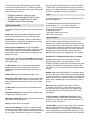
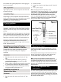
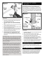
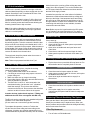
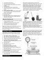
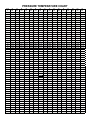
Installation and Service Guide
Reverse Osmosis System with Quick-Connect Fittings
USRO4-50-qc-38-USA / USRO4-60-qc-38-USA / USRO4-100-QC-38-USA
USRO5-50-qc-38-USA / USRO5-60-qc-38-USA / USRO5-100-QC-38-USA
Please read this manual carefully
before attempting installation
System and Faucet Diagram
1
Insert tube
How to make a Quick-Connect Connection
1. Fitting grips before it seals. Ensure tube is pushed into the tube stop.
2
3
Push up to tube stop
Pull to check secure
2. Push the tube into the fitting, to the tube stop. The collet (gripper) has
stainless steel teeth which hold the tube firmly in position while the O-ring
provides a permanent leak-proof seal.
3. Pull on the tube to check that it is secure. It is a good practice to test
the system prior to leaving site and/or before use.
4. To disconnect, ensure the system is depressurized before removing the
tube. Push in collet squarely against face of fitting. With the collet held in
this position, the tube can be removed.
The fitting can then be re-used.
4
Disconnecting
Note: See exploded diagram (on last page of this
manual) regarding locking clips and plugs.
Your Reverse Osmosis (RO) System has been tested
to ensure it will operate correctly. The following periodic
maintenance is recommended so your system will provide
years of trouble-free service:
•
•
•
•
Prefilters (sediment) Once per year
Prefilter (carbon block(s)) Once per year
RO Membrane Usually Every 2 years
Postfilter (carbon) Once per year
System Components
The following components make up your reverse osmosis
system:
Prefilter #1 (sediment) Melt Blown Polypropylene filter
removes larger particles such as dirt, rust & sediment.
Prefilter #2 (& 3 if applicable) 10 Micron Carbon Block
removes chlorine and chemical contaminants in the feed
water and protects the RO membrane.
Reverse Osmosis Membrane Thin Film Composite
Membranes reduces dissolved minerals, metals, and salts.
In this process, harmful compounds are separated by
the membrane from the water, and the contaminants are
flushed to the drain.
A coconut shell activated carbon postfilter is provided for
a final “polish” and to remove tastes, odors and to provide
great tasting water.
The RO module is the main component and holds the
prefilters and membrane, and postfilter. A bracket is
provided so they can be mounted under the sink or in a
basement.
Bladder tank holds RO purified water, ready to use.
Automatic shut-off valve closes when the storage tank is
full and shuts off the water supply to conserve water. The
valve activates when the tank pressure is 2/3 of the feed
pressure.
The RO Faucet is used to dispense purified water when
you want it.
Feed water saddle valve connects to the cold water line
to supply water to the RO system.
Wastewater saddle valve connects to the drain to remove
reject water from the RO system.
Tubing connects all RO components.
Quick-Connect fittings are used for necessary tubing
connections. These fittings connect by pushing the tube
into the fitting past a slight resistance until the tube bottoms
out in the fitting. Simply make a clean cut in your tubing
and gently push in the tubing until it will not go any further.
To ensure that your tubing has made a snug fit, pull back
gently on the tubing; it should catch. Always check for leaks
to ensure a watertight connection. (see Figure 1)
Tools
The following tools may be necessary, depending on each
particular installation:
⅜” variable speed electric drill (2,500 RPM is best for
stainless steel); ⅛”, ¼” & ½” metal cutting bits
⅛”, ¼” & ½” Concrete drill bits (for porcelain sinks)
Phillips head screw driver
6” adjustable wrench
Teflon tape & Plastic tubing cutter
Hammer & Center punch
System Location
Your RO system may be installed under a sink or in a
basement. Do not install unit where it would be exposed to
freezing temperatures. Connecting to an icemaker or other
remote location can also be considered if a connection can
be made without using more than 12” of tubing, otherwise
a delivery pump may be needed. Farther runs can be
attempted and a pump can be added later only if needed.
Guidelines for component placement are as follows:
Faucet should be placed on, or near the sink where
drinking/cooking water is normally required. A 2” flat
surface is required to mount faucet if an existing hole is not
available. The thickness of the mounting surface should
not exceed 1¼” or a faucet extension (not supplied) will be
needed.
Bladder Tank maybe placed where it is convenient, within
ten feet of the faucet. Under the sink or in a nearby cabinet
or in basement rafters are excellent choices. Full tanks can
weigh more than thirty pounds; so make sure any shelving
used is secure. Bladder tank can be placed on its side or
upright.
RO Unit may be mounted on either side of the sink,
in the back of a cabinet, or in the basement. Mounting
the unit on the left or the right side of the cabinet under
the sink provides for easier access to the unit for future
maintenance.
A Faucet Adaptor and Ball Valve Shut-Off are used
to supply feed water to the RO unit and provide an easy
ability to shut off the water supply when servicing the unit.
These are shown in Figure 2.
A Drain Saddle is used to make a waste water connection
with your drain under the sink. This is designed to fit
around a standard 1-1/2” OD drainpipe. The drain saddle
valve should always be installed before (above) the p-trap
and on the vertical or horizontal tailpiece. Do not install the
drain saddle near a garbage disposal to avoid clogging the
drain line with debris.
Unit preparation
Open shipping carton, remove components and check that
all parts are present.
Installation Steps
All plumbing must be completed in accordance with state
and local plumbing codes. Some municipalities may require
installation by a liscensed plumber. Check your local
plumbing codes for more information.
2. Drill the pilot hole
3. Continue to enlarge hole with larger size drill bit until it
is 1/2”.
4. Clean up sharp edges
Note: Air Gap Faucets are required by some
municipalities. These faucets require a 1 ¼” hole in the sink
rather than the ½” hole required by the standard faucet
included with the RO system. To make a 1 ¼” hole to
accommodate an air gap faucet requires special tools
such as a chassis punch (stainless steel) or a Relton cutter
(porcelain) if a large enough hole is not already available.
Ask your local dealer for more information.
1. Faucet Installation
(See Figure 1)
If the sink has a sprayer, it may be disconnected for faucet
installation. A pipe cap or plug will be necessary to seal the
sprayer connection or sprayer can be left connected under
the sink.
When making the faucet hole (if a sprayer or other existing
hole in not being used), check below the sink to make sure
the drill will not interfere with anything under the sink. A 2”
flat surface on the sink is required for mounting the faucet.
The faucet should be positioned so it flows into the sink
and the spout should be allowed to swivel freely for
convenience. If an existing hole is being used to mount the
faucet, proceed to Step 2.
Installation procedures for Porcelain,
Enamel, Ceramic on Metal, or Cast Iron:
Precautions must be taken to penetrate the porcelain
through to the metal base and prevent chipping or
scratching.
Procedures:
1. Mark the center with center punch for the 1/4” pilot
hole.
2. Carefully drill pilot hole with masonry pit through
porcelain and stop when metal shows. (Use light
pressure and slow speed)
3. Switch the bit to a standard metal cutting bit to continue
to cut through the metal below the porcelain surface.
4. Continue to enlarge the pilot hole with larger masonry
& metal cutting bits until the hole is 1/2”.
Installation procedures for
Stainless Steel Sinks:
Procedures:
1. Mark the center with center punch for the 1/4” pilot
hole.
2. Mounting the Faucet
Disassemble hardware from the treaded shank. Chrome
base plates and rubber washers slide up the shank to the
faucet body.
Feed threaded shank through the sink hole and orient the
faucet. From below sink, slide lock washer and hex nut
over threaded shank and tighten with a wrench.
Note: It is best to have someone hold the faucet from
above the sink to keep it from moving out of place. If this is
not possible then tighten the hex nut until it is just slightly
less than completely tight. Then turn the faucet base from
above the sink, tightening it while orienting the faucet in the
desired location
.
3. John Guest Angle Stop Valve
(See Figure 2)
The John Guest Angle Stop Valve provides a simple, easy
connection between the angle stop (cold water shut-off)
and the bottom of the riser tube. The Angle Stop Valve has
built-in shut-off and provides the feed supply connection for
the reverse osmosis system.
4. Drain Saddle Valve Installation
(See Figure 3)
A Drain Saddle is used to make a wastewater connection
with the drain under the sink, which is designed to fit
around a standard 1-1/2” OD drainpipe. The drain saddle
valve should always be installed before (above) the p-trap
and on a vertical or horizontal drain. Do not install the drain
saddle near a garbage disposal to avoid clogging the drain
line with debris.
Procedures:
1. Shut-off the cold water supply using the angle stop
shut-off located under your sink.
2. After shutting off the valve, relieve the pressure by
opening the handle on your faucet on the cold water
side.
3. Using an adjustable wrench, disconnect the riser tube
from the existing cold water shut-off.
4. Move the tubing away from the valve to make room for
the John Guest Angle Stop Valve.
5. Connect the swivel end of the John Guest Angle Stop
Valve to the threads on the cold water shut-off. This
connection should only be hand tight.
6. Connect the riser tube to the male end of the John
Guest Angle Stop Valve and tighten with a wrench.
7. Connect a length of 1/4” tubing between the John
Guest Fitting on the Angle Stop Valve and the inlet of
the RO unit.
Flexible Riser Tubes - Most riser tubes that are used today are
made of flexible material, either braided stainless steel, braided
plastic or gray 3/8” plastic tubing. These flexible tubes are the
easiest to use with the John Guest Angle Stop Valve because
the 2” of additional space needed for the Faucet Adaptor can be
easily accommodated by flexing this kind of riser. A shorter riser
tube will not be needed.
Copper Riser Tubes - If your riser tube is made of copper you
will need to either make a bend in the copper to allow for the
2” of space needed for the John Guest Angle Stop Valve. If the
copper tube is 3/8”, bending it can be done easily by hand.
The John Guest Angle Stop Valve works with 3/8” shut-off
valves and riser tubes. In some cases, older plumbing may
use a larger size shut-off and riser tube. In this case, it would
be necessary to either replace the old valve and riser tube
with new 3/8” parts, or use an alternative connection to draw
the water supply to the reverse osmosis system. Alternatives
include self piercing valves, T fittings, and faucet adaptors that
connect between the faucet and the top of the riser tube.
Please consult your distributor or an installation professional for
additional assistance.
Procedures:
1. Position the drain saddle valve at selected location and
mark for the opening.
2. Drill 1/4” hole at mark through one side of pipe.
3. Remove backing from gasket and place adhesive side
to the fitting half of drain clamp around hole.
4. Position both halves of drain saddle on drain pipe so
the opening aligns with drilled hole. Use a small drill bit
to verify that drain clamp is properly aligned.
5. Secure drain saddle clamp on valve with bolts and nuts
provided. (Do not over tighten and make sure there is
equal space between saddle halves on each side)
5. Initial tubing connections
For convenience on under sink installations it may be
advisable to complete under sink tubing connections at this
time.
6. RO Component Installation
Install RO membrane O-ring end first, carbon prefilter(s)
and sediment pre filter in vertical mounted housings. Be
sure RO Membrane is pushed into Membrane housing
as far as it will go. It is recommended that filters and
membranes be handled with clean or gloved hands.
7. RO Unit Installation
The RO unit is normally mounted to the right or left sink
cabinet sidewall, depending on where supply tank is to be
located. Generally the unit is installed at the front of the
cabinet and the tank at the rear.
To mount the unit, elevate it at least 2” off the floor, level
it and mark the location of mounting holes needed. Drill
hole for mounting screws and install screws allowing the
mounting bracket slots to slip over them.
Note: If the cabinet sidewalls are not solid, unit may sit
on the floor with screws used just to keep it against the
cabinet in a vertical position.
8. Pre-fill & Supply Tank Placement
Pre-filling the storage tank is recommended so there is
sufficient pressure to check for leaks and water to flush
the carbon post filter. To do this connect the feed line that
will serve the RO unit directly to the bladder tank. A 3/8” x
1/4” reducer is provided for this purpose. Allow the water to
fill the bladder until it stops. Close the tank valve, shut off
the feed pressure, release the tube from the reducer and
remove the reducer from the tank valve.
The supply tank should be placed under the counter or
within 10 feet of the RO unit.
Note: Tanks are pre-pressurized with air at 7 psi.
9. Final Tubing Connections
With all components in place, complete final tubing
connections with these guidelines:
1. Tubing should follow contour of the cabinets.
2. Cut tubing to correct length using square cuts and a
proper cutting tool
3. Make sure there are no crimps in the tubing.
4. Keep tubing from the RO unit to the tank and faucet as
short as possible for good flow.
5. The Drain line is a short ¼” tube connected to the
membrane housing. On this tube is a 3” cylindrical
drain flow restrictor. This is where the drain line
connects to the RO unit. Do not remove the drain flow
restrictor as this will cause a failure in the system.
Icemaker hookup (optional and requires a T fitting and
additional shut-off valve not supplied with RO unit)
The RO unit can be connected to any standard refrigerator
icemaker or ice maker/water dispenser.
(Do not connect to a commercial type bar icemaker)
To complete this operation, connect a T with a shut
off valve into the faucet tubing and route tubing to the
refrigerator. (Hooking up to existing copper tubing is not
recommended due to possible corrosion) Turn off icemaker
inside freezer prior to turning off the existing tap water
supply line to the refrigerator. Turn on the icemaker after
the RO system has been drained several times and the
tank has a full supply of water.
Icemaker lines are often run in the rafters of unfinished
basements or finished basements with drop ceilings and
then up to the fridge. If the basement has a hard ceiling,
this won’t be an option and the line would have to be run
through cabinets. In cases where a basement or cabinets
connecting sink and fridge are not available, icemaker
connections cannot be made.
Note: Before any service is performed on the RO system,
turn off icemaker valve and icemaker unit. Turn back on
only after RO system has been sanitized and flushed out.
System Start-up
Prior to start-up:
1. Check all fitting connections.
2. Open ball valve shut-off, allow system to pressurize
and check for leaks.
3. Open valve on bladder tank and open faucet until
water flows.
4. Close faucet, wait five minutes and check for leaks.
5. Allow system to produce a full tank of RO water. (2-3
hours)
Flushing System and Checking Operation
1. Flip the faucet lever up and this will keep faucet on. Do
this and allow tank to completely drain of all water.
! Do not use this water !
2. Close faucet and re-inspect system for leaks.
3. Allow system to produce water for 4 hours, at this point
the bladder tank will be full.
4. Open faucet again and allow tank to empty for a
second time.
! Do not use this water !
5. Close faucet and allow unit to produce another tank of
water.
6. At this point supply line to ice maker connection
(optional) may be opened and RO water is ready to be
consumed.
Replacing Filters & Sanitizing The System
Each year the filters in the system should be replaced.
Usually the membrane can be replaced every other year,
but the prefilters and post-filter should be changed annually
and in some cases more often.
Filter Replacement
1. Turn off valve on RO bladder tank.
2. Turn off feed water pressure.
3. Open RO faucet to relief pressure.
4. Using the supplied housing wrench remove the filter
housing.
5. Discard old filters.
6. Clean filter housings with a cleaning brush
7. Follow sanitizing steps in “Sanitizing the System”
section
8. Install new filters in system.
9. Remove and replace GAC Post filter. Remove fittings
from old post filter, re-apply Teflon tape and install
fittings in new post filter.
10. Turn on feed pressure.
11. Open tank valve.
12. Allow water in tank to flush out post filter and run to
drain until empty. Run 2 more complete batches to
drain before using water.
RO Systems are highly sensitive to pressure and
temperature. RO Membranes always perform better under
higher pressures. They produce more water, faster, and
of better quality with high pressure. The vast majority of
problems with RO Systems are a result of low pressure.
The effects of low pressure include water constantly
running to the drain, slow water production and low water
volume available in storage tank. In these cases where low
pressure exists, a booster pump will be required.
Membrane Replacement
1. Remove the supply tube from the end of the membrane
housing that has only 1 tube.
2. Unthread the cap from the membrane housing.
3. Remove membrane using a pair of pliers.
4. Clean membrane housing with a brush.
Note: When installing a new membrane be sure to push
the membrane into the housing as far as it will go.
Each time the filters are replaced it is recommended that
the system be sanitized.
Sanitizing the System
After all filters are removed from the system, housings
have been cleaned, tank is empty, and faucet is open…
1.
2.
3.
4.
5.
6.
7.
Add 1 gallon of water to a clean bucket.
Add 1 teaspoon of unscented household bleach.
Add 1 cup of this solution to each filter housing.
Tighten filter housings with solution on RO assembly.
Connect membrane housing and feed tube.
Open tank valve and feed pressure valve.
Allow water to fill the RO housing assembly until water
comes out of faucet.
8. Close the faucet
9. Allow water to run for 5 minutes.
10. Shut-off feed pressure.
11. Allow solution to stand for 30 minutes.
12. Open faucet and allow system to drain.
13. Remove water from housings before installing new
filters and membrane.
14. Install new filters, tighten housings, and reconnect all
tubing connections.
15. Open feed pressure valve and check for leaks.
16. Allow the system to make a full tank of water.
17. Run 2 cycles to drain to rinse out sanitizing solution
before using water.
Troubleshooting
On the following page is a table showing RO Membrane
performance over a range of temperatures and pressures.
Membranes are tested at 65 psi of pressure and
temperature of 77 degrees. For each incremental change
in either variable, membrane performance changes
accordingly. Higher pressures increase production and vice
versa.
To troubleshoot a poor performing RO System an accurate
measure of the pressure and temperature of water will be
required. This will require a pressure gauge to determine
exactly what the water pressure is that is feeding the
membrane. Descriptions of water pressure such as good,
high or strong, unfortunately, are no help in diagnosing an
RO System.
Pressure Temperature Chart
Temp
°F
35
PSI
40
PSI
45
PSI
50
PSI
55
PSI
60
PSI
65
PSI
70
PSI
75
PSI
80
PSI
85
PSI
90
PSI
95
PSI
100
PSI
105
PSI
110
PSI
45
0.2321
0.2653
0.2985
0.3316
0.3648
0.3979
0.4311
0.4643
0.4974
0.5306
0.5638
0.5969
0.6301
0.6632
0.6964
0.7296
46
0.2417
0.2762
0.3108
0.3453
0.3798
0.4144
0.4489
0.4834
0.5179
0.5525
0.5870
0.6215
0.6561
0.6906
0.7251
0.7597
47
0.2513
0.2872
0.3231
0.3590
0.3949
0.4308
0.4667
0.5026
0.5385
0.5744
0.6103
0.6462
0.6821
0.7179
0.7538
0.7897
48
0.2609
0.2981
0.3354
0.3726
0.4099
0.4472
0.4844
0.5217
0.5590
0.5962
0.6335
0.6708
0.7080
0.7453
0.7826
0.8198
49
0.2704
0.3091
0.3477
0.3863
0.4250
0.4636
0.5022
0.5409
0.5795
0.6181
0.6568
0.6954
0.7340
0.7726
0.8113
0.8499
50
0.2800
0.3200
0.3600
0.4000
0.4400
0.4800
0.5200
0.5600
0.6000
0.6400
0.6800
0.7200
0.7600
0.8000
0.8400
0.8800
51
0.2896
0.3309
0.3723
0.4137
0.4550
0.4964
0.5378
0.5791
0.6205
0.6619
0.7032
0.7446
0.7860
0.8274
0.8687
0.9101
52
0.2991
0.3419
0.3846
0.4274
0.4701
0.5128
0.5556
0.5983
0.6410
0.6838
0.7265
0.7692
0.8120
0.8547
0.8974
0.9402
53
0.3087
0.3528
0.3969
0.4410
0.4851
0.5292
0.5733
0.6174
0.6615
0.7056
0.7497
0.7938
0.8379
0.8821
0.9262
0.9703
54
0.3183
0.3638
0.4092
0.4547
0.5002
0.5456
0.5911
0.6366
0.6821
0.7275
0.7730
0.8185
0.8639
0.9094
0.9549
1.0003
55
0.3279
0.3747
0.4215
0.4684
0.5152
0.5621
0.6089
0.6557
0.7026
0.7494
0.7962
0.8431
0.8899
0.9368
0.9836
1.0304
56
0.3374
0.3856
0.4338
0.4821
0.5303
0.5785
0.6267
0.6749
0.7231
0.7713
0.8195
0.8677
0.9159
0.9641
1.0123
1.0605
57
0.3470
0.3966
0.4462
0.4957
0.5453
0.5949
0.6444
0.6940
0.7436
0.7932
0.8427
0.8923
0.9419
0.9915
1.0410
1.0906
58
0.3566
0.4075
0.4585
0.5094
0.5603
0.6113
0.6622
0.7132
0.7641
0.8150
0.8660
0.9169
0.9679
1.0188
1.0697
1.1207
59
0.3662
0.4185
0.4708
0.5231
0.5754
0.6277
0.6800
0.7323
0.7846
0.8369
0.8892
0.9415
0.9938
1.0462
1.0985
1.1508
60
0.3757
0.4294
0.4831
0.5368
0.5904
0.6441
0.6978
0.7515
0.8051
0.8588
0.9125
0.9662
1.0198
1.0735
1.1272
1.1809
61
0.3853
0.4403
0.4954
0.5504
0.6055
0.6605
0.7156
0.7706
0.8256
0.8807
0.9357
0.9908
1.0458
1.1009
1.1559
1.2109
62
0.3949
0.4513
0.5077
0.5641
0.6205
0.6769
0.7333
0.7897
0.8462
0.9026
0.9590
1.0154
1.0718
1.1282
1.1846
1.2410
63
0.4044
0.4622
0.5200
0.5778
0.6356
0.6933
0.7511
0.8089
0.8667
0.9244
0.9822
1.0400
1.0978
1.1556
1.2133
1.2711
64
0.4140
0.4732
0.5323
0.5915
0.6506
0.7097
0.7689
0.8280
0.8872
0.9463
1.0055
1.0646
1.1238
1.1829
1.2421
1.3012
65
0.4236
0.4841
0.5446
0.6051
0.6656
0.7262
0.7867
0.8472
0.9077
0.9682
1.0287
1.0892
1.1497
1.2103
1.2708
1.3313
66
0.4332
0.4950
0.5569
0.6188
0.6807
0.7426
0.8044
0.8663
0.9282
0.9901
1.0520
1.1138
1.1757
1.2376
1.2995
1.3614
67
0.4427
0.5060
0.5692
0.6325
0.6957
0.7590
0.8222
0.8855
0.9487
1.0120
1.0752
1.1385
1.2017
1.2650
1.3282
1.3915
68
0.4523
0.5169
0.5815
0.6462
0.7108
0.7754
0.8400
0.9046
0.9692
1.0338
1.0985
1.1631
1.2277
1.2923
1.3569
1.4215
69
0.4619
0.5279
0.5938
0.6598
0.7258
0.7918
0.8578
0.9238
0.9897
1.0557
1.1217
1.1877
1.2537
1.3197
1.3856
1.4516
70
0.4715
0.5388
0.6062
0.6735
0.7409
0.8082
0.8756
0.9429
1.0103
1.0776
1.1450
1.2123
1.2797
1.3470
1.4144
1.4817
71
0.4810
0.5497
0.6185
0.6872
0.7559
0.8246
0.8933
0.9621
1.0308
1.0995
1.1682
1.2369
1.3056
1.3744
1.4431
1.5118
72
0.4906
0.5607
0.6308
0.7009
0.7709
0.8410
0.9111
0.9812
1.0513
1.1214
1.1915
1.2615
1.3316
1.4017
1.4718
1.5419
73
0.5002
0.5716
0.6431
0.7145
0.7860
0.8574
0.9289
1.0003
1.0718
1.1432
1.2147
1.2862
1.3576
1.4291
1.5005
1.5720
74
0.5097
0.5826
0.6554
0.7282
0.8010
0.8738
0.9467
1.0195
1.0923
1.1651
1.2379
1.3108
1.3836
1.4564
1.5292
1.6021
75
0.5193
0.5935
0.6677
0.7419
0.8161
0.8903
0.9644
1.0386
1.1128
1.1870
1.2612
1.3354
1.4096
1.4838
1.5579
1.6321
76
0.5289
0.6044
0.6800
0.7556
0.8311
0.9067
0.9822
1.0578
1.1333
1.2089
1.2844
1.3600
1.4356
1.5111
1.5867
1.6622
77
0.5385
0.6154
0.6923
0.7692
0.8462
0.9231
1.0000
1.0769
1.1538
1.2308
1.3077
1.3846
1.4615
1.5385
1.6154
1.6923
78
0.5480
0.6263
0.7046
0.7829
0.8612
0.9395
1.0178
1.0961
1.1744
1.2526
1.3309
1.4092
1.4875
1.5658
1.6441
1.7224
79
0.5576
0.6373
0.7169
0.7966
0.8762
0.9559
1.0356
1.1152
1.1949
1.2745
1.3542
1.4338
1.5135
1.5932
1.6728
1.7525
80
0.5672
0.6482
0.7292
0.8103
0.8913
0.9723
1.0533
1.1344
1.2154
1.2964
1.3774
1.4585
1.5395
1.6205
1.7015
1.7826
81
0.5768
0.6591
0.7415
0.8239
0.9063
0.9887
1.0711
1.1535
1.2359
1.3183
1.4007
1.4831
1.5655
1.6479
1.7303
1.8126
82
0.5863
0.6701
0.7538
0.8376
0.9214
1.0051
1.0889
1.1726
1.2564
1.3402
1.4239
1.5077
1.5915
1.6752
1.7590
1.8427
83
0.5959
0.6810
0.7662
0.8513
0.9364
1.0215
1.1067
1.1918
1.2769
1.3621
1.4472
1.5323
1.6174
1.7026
1.7877
1.8728
84
0.6055
0.6920
0.7785
0.8650
0.9515
1.0379
1.1244
1.2109
1.2974
1.3839
1.4704
1.5569
1.6434
1.7299
1.8164
1.9029
85
0.6150
0.7029
0.7908
0.8786
0.9665
1.0544
1.1422
1.2301
1.3179
1.4058
1.4937
1.5815
1.6694
1.7573
1.8451
1.9330
86
0.6246
0.7138
0.8031
0.8923
0.9815
1.0708
1.1600
1.2492
1.3385
1.4277
1.5169
1.6062
1.6954
1.7846
1.8738
1.9631
87
0.6342
0.7248
0.8154
0.9060
0.9966
1.0872
1.1778
1.2684
1.3590
1.4496
1.5402
1.6308
1.7214
1.8120
1.9026
1.9932
88
0.6438
0.7357
0.8277
0.9197
1.0116
1.1036
1.1956
1.2875
1.3795
1.4715
1.5634
1.6554
1.7474
1.8393
1.9313
2.0232
89
0.6533
0.7467
0.8400
0.9333
1.0267
1.1200
1.2133
1.3067
1.4000
1.4933
1.5867
1.6800
1.7733
1.8667
1.9600
2.0533
2.0834
90
0.6629
0.7576
0.8523
0.9470
1.0417
1.1364
1.2311
1.3258
1.4205
1.5152
1.6099
1.7046
1.7993
1.8940
1.9887
91
0.6725
0.7685
0.8646
0.9607
1.0568
1.1528
1.2489
1.3450
1.4410
1.5371
1.6332
1.7292
1.8253
1.9214
2.0174
2.1135
92
0.6821
0.7795
0.8769
0.9744
1.0718
1.1692
1.2667
1.3641
1.4615
1.5590
1.6564
1.7538
1.8513
1.9487
2.0462
2.1436
93
0.6916
0.7904
0.8892
0.9880
1.0868
1.1856
1.2844
1.3832
1.4821
1.5809
1.6797
1.7785
1.8773
1.9761
2.0749
2.1737
94
0.7012
0.8014
0.9015
1.0017
1.1019
1.2021
1.3022
1.4024
1.5026
1.6027
1.7029
1.8031
1.9032
2.0034
2.1036
2.2038
95
0.7108
0.8123
0.9138
1.0154
1.1169
1.2185
1.3200
1.4215
1.5231
1.6246
1.7262
1.8277
1.9292
2.0308
2.1323
2.2338