1
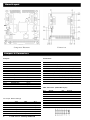
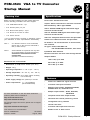
Startup Manual Specifications Packing List Before you begin installing your card, please make sure that the following materials have been shipped: Form Factor: PC/104 Form Factor Chipset: Altech 2139 CRT-to-TV Converter Controller • 1 ea. PCM-3524 module x 1 pc External Memory: 1M*16 Type SDRAM • 4 ea. Screws (3mm) x 4 pcs CRT-in: Standard RGB Signals with female D-type Connector and box-header • 4 ea. Bronze stick (6mm) x 4 pcs • 1 ea. D-sub 15 to D-sub 15 cable CRT-out: Standard RGB Signals with female D-type Connector and box-header • 1 ea. User's manual If any of these items is missing or damaged, contact your distributor or sales representative immediately. Note 1: Note 2: For detailed contents of the PCM-3524, please refer to the enclosed CD-ROM or disk (in PDF format). Acrobat Reader is required to view any PDF file. Acrobat Reader can be downloaded at: www.adobe.com/Prodindex/acrobat/ readstep.html (Acrobat is a trademark of Adobe.) Video-out: Composite RCA Connector and pin-header S-Video out: S-Video Connector and pin-header DC Power-in: via PC/104 Interface or DC-Connector, auto switched TV types: NTSC, NTSC-EIAJ and PAL S/D/G/H/I/M/N standards, auto detect Input Mode: Auto Detection Extension Interface: One 8-bit stack through PC/104 PCM-3524 VGA to TV Converter PCM-3524 VGA to TV Converter Graphics Modes 1024 x 768, up to 60Hz Mechanical and environmental 800 x 600, up to 85Hz • Dimensions: (L x W): 96mm x90mm (3.8" x3.6") 640 x 480, up to 85Hz • Weight: 125 g • Operating temperature: 0 ~ 60° C (32 ~ 140° F) • Storage temperature: -40 ~ 85° C ( -40 ~ 185° F) • Operating humidity: 0% to 90% relative humidity, non-condensing Features • Power supply voltage: 9V (external) or PC104 • Power requirements: 6 ~ 12V @ 600mA (9V Recommended) For more information on this and other Advantech products, please visit our website at: http://www.advantech.com http://www.advantech.com/epc For technical support and service, please visit our support website at: • Flicker free VGA-to-TV signal converter • 3-Channel 8 bit input conversion • Multiple input formats: 640x480 60/75/85Hz, 800x600 60/75 Hz, 1024x768 60 Hz • Multiple output formats - NTSC, NTSC-EIA, PAL-B/G/H/I • Composite and S-video output formats • Horizontal and vertical positioning control • Configuration set by switches • Internal color bars http://www.advantech.com/support • 3-Channel 9-bit output D/A converters This manual is for the PCM-3524 • Blanks to blue or black screen Part No. 2006352410 Printed in Taiwan 1st Edition August, 2002 PCM-3524 Startup Manual 1 Board Layout Component Placement Dimensions Jumpers & Connectors Connectors Jumpers JUMPER JP1 JP2 JP3 JP4 JP5 JP6 JP7 JP8 JP9 JP10 JP11 JP12 JP14 FUNCTION TD0 TD1 RESERVED PAL_NTSC PWRDN RGB_OUT RESERVED YUV_OUT RESERVED RESERVED RESERVED RESERVED POWER Selection Default Short Short Open Short Short Short Open Short Open Open Open Open Short 2-3 Label CN1 CN2 CN3 CN4 CN5 CN6 CN7 J1 J2 J3 VGA Connector (CN2/CN3 16-pin) TV Output Mode Settings NTSC NTSC-EIA PAL-BDGHI PAL-N PAL-Comb-N PAL-M 2 JP4 Short Short Open Open Open Short JP2 Short Short Short Short Open Open Function VGA output (DB15 female) VGA output (16-pin box-header) VGA input (16-pin box-header) VGA input (DB15 female) Composite Video output (2-pin header) DC power in S-Video output (4-pin header) Composite Video output (RCA jack) DC power in (DC power jack) S-Video output (4pin mini-DIN) JP1 Short Open Open Short Open Short PCM-3524 Startup Manual Pin 1 3 5 7 9 11 13 15 Signal Red Green Blue N/A GND GND AGND DDC CLK Pin 2 4 6 8 10 12 14 16 Signal AGND N/A AGND DDC DAT AGND Horz Sync Vert Sync N/C S-Video Output Connector (CN7/J3) VGA Connector (CN1/CN4 15-pin) Pin 1 4 7 10 13 Signal Red N/A AGND GND H Sync Pin 2 5 8 11 14 Signal Green GND AGND N/A V Sync Pin 3 6 9 12 15 Signal Blue AGND N/A DDC DAT DDC CLK Pin 1 2 3 4 Signal GND CSYNC CHROMA LUMA Composite Video Output Connector (CN5/J1) Switches and VR Pin 1 2 Switches SWITCH SW1 SW2 SW3 SW4 SW5 SW6 SW7 SW8 SW9 SW10 VR1 Signal COMP GND DC Power Connector (CN6) Pin 1 2 3 4 Signal +12V GND GND +5V FUNCTION RESET POS_U POS_L POS_R POS_D ZOOM BLANK OUPUT FREEZE OUTPUT FILTER MODE SELECTS OVERSCAN OR UNDERSCAN BRIGHTNESS DC Power Connector Jack (J2) 6~12V @ 600mA (9V Recommended) Position Adjustment Switches FILTER MODE SELECTION (SW9) cycles through selections as follows: 3-line2-lineno filtercolor barsno filter2-line3-line VGA out Switch SW2 SW3 SW4 SW5 Position adjustment up left right down VGA in TV out S-video out PCM-3524 Startup Manual 3