1
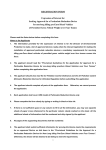
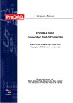
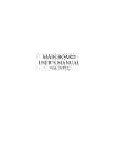
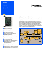
Datasheet
M C P N 75 0
CompactPCI
P e ri p h e ra l P r o c e s s or
Low-power, high-performance CompactPCI board
The MCPN750 series of CompactPCI® boards provides the performance of Motorola’s
PowerPlus Architecture and the ability to be fully customized with two PCI mezzanine
cards (PMCs).
Utilizing Motorola’s low-power, high-performance MPC750 class microprocessors,
64-bit local peripheral component interconnect (PCI) bus for the on-board peripherals,
processor/memory bus to PCI bus bridge, and a 64-bit bridge to the CompactPCI
interface, the MCPN750 offers maximum performance and flexibility in just a single
CompactPCI slot. It is also fully compliant to the PICMG® 2.1 Hot Swap Specification,
making it the ideal choice for high availability applications.
32KB/32KB L1 cache; 1MB L2 cache
■
64 to 256MB of ECC DRAM
■
Up to 5MB on-board Flash memory
■
Optional CompactFlash memory card socket
■
10/100Mb/s Ethernet interface
■
Two 32/64-bit PMC expansion slots with front-panel
or backplane I/O
■
Two universal serial bus (USB) ports
■
Four asynchronous serial ports
■
On-board debug monitor with self-test diagnostics
■
8K x 8 NVRAM and time-of-day clock with
replaceable battery backup
■
Four 32-bit timers, one watchdog timer
■
64-bit CompactPCI interface
■
Single CompactPCI slot, even when fully configured
■
Compliant with PICMG 2.1 Hot Swap Specification
Memory
Expansion
L2
Cache
PCI Bridge
Flash
MPC750
Class
Processor
PCI Bridge
1MB
PowerPC Architecture
Bus – 64-bit
CompactPCI Bus
64-bit
PMC I/O
EIDE
PCI to ISA/IDE
Bridge
IDE Flash
Socket
PMC
Slot
Memory
Controller
ECC DRAM
64MB to 256MB
Flash
4/8MB
Memory Bus – 144-bit
IDE Bus – A16/D8
USB USB
SNAPHAT
Battery
■
J4
MPC750 class microprocessor
J1/J2
■
NVRAM
RTC
2 Serial
Sync/Async
Serial Serial
Super I/O
Kbd/
Mouse
Parallel
PCI Bus – 64-bit
Ethernet
10/100BaseT
Async Async
Serial Serial
MCPN750 Details
MCPN750 DETAILS
Transition Modules
The TM-PIMC-0001 transition module provides one RJ-45 Ethernet connector, two RJ-45 serial connectors and two
headers (providing access to the asynchronous serial ports configured as EIA DTE), one socket for an optional
CompactFlash memory card, and two PIM slots.
The TMCPN710 transition module provides industry-standard connector access to the two USB Series A receptacles,
two RJ-45 connectors and two headers (providing access to the asynchronous serial ports configured as EIA DTE),
and two sockets for optional CompactFlash memory cards. Also, on the TMCPN710-002 model there are two HD-68
connectors available to provide access to the PMC backplane I/O.
Firmware Monitor
Firmware must fulfill the traditional functions of test and initialization, in addition to operating system boot support.
The MCPN750 firmware monitor exceeds these requirements plus expands features like power-up tests with
extensive diagnostics, as well as a powerful evaluation and debug tool for simple checkout or when high-level
development debuggers require additional support. All this is included with the MCPN750 firmware, plus it supports
booting both operating systems and kernels.
IEEE P1386.1 Compliant PMC Slots
The MCPN750 features dual PMC ports with support for both front-panel and backplane I/O. In addition to providing
high performance expansion I/O, the IEEE P1386.1 compliant PMC ports form a common architecture for future
generations of products. Changing I/O requirements can be satisfied by simply replacing PMCs while reusing the
same base platform and software, reducing the long-term cost of ownership.
PowerPlus Architecture
The PowerPlus Architecture is a processor and bus architecture fully optimized to get the maximum performance
from the PowerPC architecture-compatible microprocessor family, the PCI bus, and the CompactPCI interface. The
outstanding performance of processor boards based on the PowerPlus Architecture is not due to a single factor. A
number of elements in the design of the PowerPlus Architecture contribute to its outstanding performance including
the processor/memory subsystem, high-speed local bus, optimally decoupled architecture, decoupling the processor
from PCI, and the advanced CompactPCI interface, which reduces PCI delays. Contact your sales representative for
details.
Operating Systems and Kernels
MCPN750 supports booting a complete range of real-time operating systems and kernels, which may be purchased
from the following companies:
Integrated Systems, Inc.:
Monte Vista Software:
Wind River Systems, Inc.:
2
MCPN750
pSOSystem
Linux
VxWorks
Specifications
SPECIFICATIONS
Processor
Asynchronous Serial Ports
Microprocessor:
On-chip Cache (I/D):
Controller:
366/466 MHz MPC750 class
Number of Ports:
32K/32K
Configuration:
Memory
Async Baud Rate, b/s
max.:
Main Memory:
Dynamic RAM
Capacity (60ns):
256MB
Capacity (50ns):
64MB, 128MB, or 256MB
Single Cycle
Accesses:
Read Burst Mode
(50ns):
8-1-1-1 idle; 2-1-1-1 aligned page hit
Write Burst Mode:
4-1-1-1 idle; 3-1-1-1 aligned page hit
Architecture:
Parity/ECC:
L2 Cache:
Cache Bus Clock
Frequency:
Flash:
Capacity:
Removable Battery:
1MB
Processor clock divided by 2.5 (366 MHz)
or divided by 3.0 (466 MHz)
On-board programmable
1MB via two 32-pin PLCC/CLCC sockets;
4MB surface mount
8KB, 4KB available for users
50 years at 55° C
10 years at 100% duty cycle
Yes
Intel 21554
Address/Data:
A32/D32/D64
PCI Bus Clock:
33 MHz
Signaling:
PCI Local bus DMA:
Connector:
3.3V output; input defined by VIO
Intel 21143
10/100Mb/s
Yes, with PCI burst
RJ-45 on front panel (optionally to J5)
Counters/Timers
TOD Clock Device:
Real-Time
Timers/Counters:
Watchdog Timer:
Two Series A receptacles on front panel;
also routed to J3 for optional use of two
Series A receptacles on TMCPN710
Address/Data:
A32/D32/D64, PMC JN1, JN2, JN3, JN4
connectors
PCI Bus Clock:
33 MHz
Signaling:
Power:
5V
+3.3V, +5V, ±12V, 7.5 watts maximum per
PMC slot
Two single-wide or one double-wide, front
panel I/O or J3 and J5 I/O
Note: Due to high component density, uninsulated traces and vias are
located in the MCPN750 I/O keepout area. If installed, PMC modules
having conductive I/O connectors could contact these traces and vias.
If full IEEE 1386-2001 compliance is required, an insulating shield (for
example, Kapton tape) should be installed.
Hot Swap
Compliant with PICMG Hot Swap Specification, Revision 1.0
Power Requirements (entry model)
(not including power required by PMC or transition module)
+3.3V ±5% +5V ±5%
+12V ±5%
–12V ±5%
MCPN750:
Controller:
82C586
IEEE P1386.1 PCI Mezzanine Card Slot
Ethernet Interface
Interface Speed:
Routed to J3; two headers on TMCPN710
Module Types:
19 clocks (2 bytes/8 bytes)
CompactPCI Interface
Controller:
Connectors:
No/Yes
260 clocks (8 byte burst)
Cell Capacity Life:
Routed to J3; also RJ-45 on TMCPN710
and TM-PIMC-0001
128-bit, 2 way interleaved
Read Access (1MB
port):
NVRAM:
Connector (COM2):
Controller:
68 clocks (32 byte burst)
Cell Storage Life:
38.4K EIA-232, 115Kb/s raw
USB
Read Access (4MB
port):
Write Access
(1MB/4MB):
EIA-574-DTE
Front panel; also RJ-45 on TMCPN710 and
TM-PIMC-0001
Connector (COM3/4):
9-1-2-1 idle; 3-1-2-1 aligned page hit
Four
Connector (COM1):
9 read/4 write
Read Burst Mode
(60ns):
16C550C UART
2.1 A typ.
2.8 A max.
2.0 A typ.
2.6 A max.
4.0 mA typ.
6.0 mA max.
1.0 mA typ.
2.0 mA max.
Demonstrated MTBF
(based on a sample of eight boards in accelerated stress environment)
Mean: 214,323 hours
95% Confidence:
76,816 hours
Board Size
M48T559; 8KB NVRAM
Height:
233.4 mm (9.2 in.)
Four 32-bit programmable
Depth:
160.0 mm (6.3 in.)
Time-out generates reset
Front Panel Height:
Width:
Max. Component
Height:
261.8 mm (10.3 in.)
19.8 mm (0.8 in.)
14.8 mm (0.58 in.)
MCPN750 3
Miscellaneous
Reset/Abort switch on front panel; three LEDs for FAIL, CPU, and hot
swap
Transition Modules
I/O Connectors
TMCPN710
Asynchronous Serial Ports:
Two RJ-45 connectors labeled as COM1 and COM2;
Two 26-pin headers as COM3 and COM4
Two 4-pin Series A receptacles
None
PMC I/O:
Two HD-68
Two PMC sites/slots
Ethernet:
Optional, one RJ-45 connector
One RJ-45 connector
USB:
CompactFlash Memory Card Interface
Controller:
Interface:
CompactFlash Cards
(optional):
Connector:
All Modules
Board Size
82C586
Height:
233.4 mm (9.2 in.)
ATA, true IDE mode
Depth:
80.0 mm (3.1 in.)
Front Panel Height:
Motorola CFLASH-xxx series
Width:
One or two standard 50-pin sockets
Environmental
Temperature:
TM-PIMC-0001
Two RJ-45 connectors labeled as COM1 and COM2;
Two 26-pin headers as COM3 and COM4
261.8 mm (10.3 in.)
19.8 mm (0.8 in.)
Safety
Operating
Nonoperating
0° C to +55° C,
forced air cooling exit
air
–40° C to +85° C
Humidity (NC):
Vibration:
All printed wiring boards (PWBs) are manufactured with a flammability
rating of 94V-0 by UL recognized manufacturers.
Electromagnetic Compatibility (EMC)
10% to 80%
10% to 90%
0.5 G RMS,
20–2000 Hz random
6.0 Gs RMS,
20–2000 Hz random
Intended for use in systems meeting the following regulations:
U.S.: FCC Part 15, Subpart B, Class A (nonresidential)
Canada: ICES-003, Class A (non-residential)
This product was tested in a representative system to the following
standards:
CE Mark per European EMC Directive 89/336/EEC with
Amendments; Emissions: EN55022 Class B; Immunity: EN55024
Ordering Information
ORDERING INFORMATION
Part Number
Description
MCPN750-1342
366 MHz MPC750, 64MB DRAM, front Ethernet
MCPN750-1352
366 MHz MPC750, 128MB DRAM, front Ethernet
MCPN750-1362
366 MHz MPC750, 256MB DRAM, front Ethernet
MCPN750-2342
366 MHz MPC750, 64MB DRAM, rear Ethernet
MCPN750-2352
366 MHz MPC750, 128MB DRAM, rear Ethernet
MCPN750-1442
466 MHz MPC750, 64MB DRAM, front Ethernet
MCPN750-1452
466 MHz MPC750, 128MB DRAM, front Ethernet
MCPN750-1462
466 MHz MPC750, 256MB DRAM, front Ethernet
Related Products
TM-PIMC-0001
One RJ-45 Ethernet, two RJ-45 async serial ports, two headers for async serial ports, CompactFlash socket,
two PIM slots
TMCPN710-001
Two RJ-45 async serial port connectors, two headers for async serial ports, two CompactFlash sockets
TMCPN710-002
Two RJ-45 async serial port connectors, two headers for async serial ports, two HD-68 connectors providing
access to PMC backplane I/O, two CompactFlash sockets
CFLASH-xxx
4
MCPN750
CompactFlash memory card
(where xxx = number of MB
Part Number
Description
Documentation
MCPN750A/IH
MCPN750 Installation and Use Manual
MCPN750A/PG
MCPN750 Programmer’s Reference Guide
TMCPN710A/IH
TMCPN710 Transition Module Installation and Use
TMPIMCA/IH
PPCBUGA1/UM and
PPCBUGA2/UM
PPCDIAA/UM
TM-PIMC-0x01 Transition Module Installation and Use
PPCBug Firmware Package User’s Manual
PPCBug Diagnostics Manual
Documentation is available for online viewing and ordering at http://www.motorola.com/computer/literature
Motorola Computer Group
Regional Offices
NORTH AMERICA: Tempe, AZ 800-759-1107 or 602-438-5720
ASIA: Shanghai, China +86 21 5292 5693
EUROPE: Loughborough, UK +44 1509 634300
PACIFIC RIM: Tokyo, Japan +81 3 5424 3101
EAST MEDITERRANEAN: Tel Aviv, Israel +972 3 568 4388
ASIA/PACIFIC: Hong Kong +852 2966 3210
www.motorola.com/computer
MOTOROLA and the Stylized M Logo are registered in the U.S. Patent and Trademark Office. All other product or
service names are the property of their respective owners. CompactPCI and PICMG are registered trademarks of PCI
Industrial Computer Manufacturers Group.
This datasheet identifies products, their specifications, and their characteristics, which may be suitable for certain
applications. It does not constitute an offer to sell or a commitment of present or future availability, and should not be
relied upon to state the terms and conditions, including warranties and disclaimers thereof, on which Motorola may
sell products. A prospective buyer should exercise its own independent judgement to confirm the suitability of the
products for particular applications. Motorola reserves the right to make changes, without notice, to any products or
information herein which will, in its sole discretion, improve reliability, function, or design. Motorola does not assume
any liability arising out of the application or use of any product or circuit described herein; neither does it convey any
license under its patent or other intellectual property rights or under others. This disclaimer extends to any prospective
buyer, and it includes Motorola’s licensee, licensee’s transferees, and licensee’s customers and users. Availability of
some of the products and services described herein may be restricted in some locations.
CN750-D4 02/03
© 2003, 2001,1998 Motorola, Inc. All rights reserved.