1
NEXCOM International Co., Ltd.
Industrial Computing Solutions
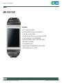
Applied Panel PC
APPC 1220T/1221T/1520T/1521T/1720T/1721T
User Manual
NEXCOM International Co., Ltd.
Published April 2011
www.nexcom.com
Contents
Contents
Preface
Chapter 2: Jumpers And Connectors
Copyright .............................................................................................. iv
Disclaimer .............................................................................................. iv
Acknowledgements ............................................................................... iv
Regulatory Compliance Statements ........................................................ iv
Declaration of Conformity....................................................................... iv
RoHS Compliance.................................................................................... v
Warranty and RMA................................................................................. vi
Safety Information ................................................................................. ix
Installation Recommendations................................................................. ix
Safety Precautions.................................................................................... x
Technical Support and Assistance............................................................ xi
Conventions Used in this Manual............................................................ xi
Global Service Contact Information.........................................................xii
Package Contents..................................................................................xiv
Ordering Information..............................................................................xv
Before You Begin...................................................................................17
Precautions............................................................................................17
Jumper Settings.....................................................................................18
Locations of the Jumpers and Connectors..............................................19
Jumpers.................................................................................................21
Connectors Pin Definitions.....................................................................24
External I/O Interface.........................................................................24
APPC 1210T/1211T/1510T/1511T.................................................24
VGA Port......................................................................................24
PS/2 Keyboard/Mouse Port............................................................25
COM1 Port (Isolation with RS422/485)..........................................25
COM2 Port (Isolation with RS422/485)..........................................26
USB Ports......................................................................................27
LAN1 Port.....................................................................................28
LAN2 Port.....................................................................................28
Line-out Jack................................................................................29
Internal Connectors...........................................................................30
Xilinx Programming Connector
(APPC 1720T/1721T/1520T/1521T only).......................................30
Panel Backlight Connector............................................................30
LVDS Panel Backlight Connector
(APPC 1220T/1221T only).............................................................31
LVDS Panel Backlight Connector
(APPC 1720T/1721T/1520T/1521T only).......................................31
LVDS Panel Backlight Connector
(APPC 1720T/1721T/1520T/1521T only).......................................32
Chapter 1: Product Introduction
APPC 1220T/1221T..................................................................................1
APPC 1520T/1521T..................................................................................4
APPC 1720T/1721T..................................................................................7
Getting to Know the APPC Series...........................................................10
Rear Top............................................................................................10
Rear Bottom......................................................................................11
Rear (APPC 1220T/1520T/1720T only)...............................................12
Rear (APPC 1221T/1521T/1721T only)...............................................13
Mechanical Dimensions..........................................................................14
Copyright © 2011 NEXCOM International Co., Ltd. All Rights Reserved.
ii
APPC 1220T/1221T/1520T/1521T/1720T/1721T User Manual
Contents
Chapter 4: BIOS Setup
Power Button Connector..............................................................33
Reset Button.................................................................................33
SATA DOM Power Connector........................................................34
SATA Power Connector.................................................................34
SATA Port.....................................................................................35
Touch Sensor Connector...............................................................35
USB Connector.............................................................................36
CompactFlash...............................................................................37
Power LED Connector...................................................................38
HDD Active LED Connector...........................................................38
Mini-PCIe Slots.............................................................................39
COM3 Connectors
(APPC 1721T/1521T/1221T only)..................................................40
COM4 Connectors
(APPC 1721T/1521T/1221T only)..................................................40
GPIO Connector...........................................................................41
Line-in/Mic-in Connector..............................................................42
Speaker-out Connector.................................................................42
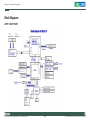
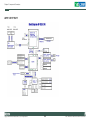
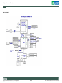
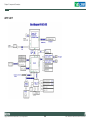
Block Diagram...................................................................................43
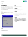
About BIOS Setup..................................................................................67
When to Configure the BIOS..................................................................67
Entering Setup.......................................................................................68
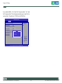
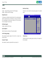
BIOS Setup Utility...................................................................................69
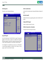
Main.................................................................................................69
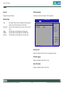
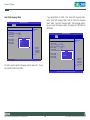
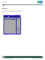
Advanced..........................................................................................70
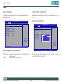
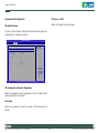
Boot..................................................................................................80
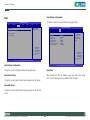
Chipset.............................................................................................83
PCIPnP..............................................................................................85
Security.............................................................................................86
Exit....................................................................................................89
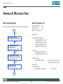
Appendix A: Watchdog Timer
WDT Programming Guide......................................................................92
Watchdog Sample Code........................................................................92
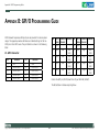
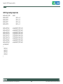
Appendix B: GPIO Programming Guide
J9 - GPIO Connector..............................................................................93
GPIO Programming Sample Code...........................................................94
Chapter 3: System Setup
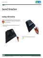
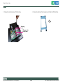
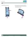
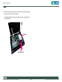
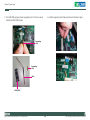
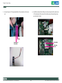
Installing a SATA Hard Drive...................................................................47
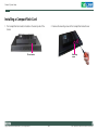
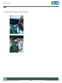
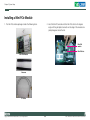
Installing a CompactFlash Card..............................................................51
Installing a SODIMM..............................................................................53
Installing a SATA DOM...........................................................................55
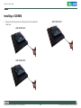
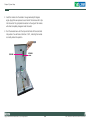
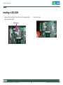
Installing a Mini PCIe Module.................................................................59
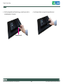
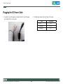
Plugging the DC Power Cable................................................................64
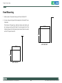
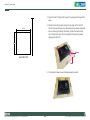
Panel Mounting.....................................................................................65
Copyright © 2011 NEXCOM International Co., Ltd. All Rights Reserved.
Appendix C: Power Consumption
Power Consumption Measurement........................................................95
iii
APPC 1220T/1221T/1520T/1521T/1720T/1721T User Manual
Preface
Preface
Copyright
Regulatory Compliance Statements
This publication, including all photographs, illustrations and software, is
protected under international copyright laws, with all rights reserved. No
part of this manual may be reproduced, copied, translated or transmitted
in any form or by any means without the prior written consent from
NEXCOM International Co., Ltd.
This section provides the FCC compliance statement for Class A devices
and describes how to keep the system CE compliant.
Declaration of Conformity
FCC
Disclaimer
This equipment has been tested and verified to comply with the limits for
a Class A digital device, pursuant to Part 15 of FCC Rules. These limits are
designed to provide reasonable protection against harmful interference
when the equipment is operated in a commercial environment. This equipment generates, uses, and can radiate radio frequency energy and, if not
installed and used in accordance with the instructions, may cause harmful
interference to radio communications. Operation of this equipment in a
residential area (domestic environment) is likely to cause harmful interference, in which case the user will be required to correct the interference
(take adequate measures) at their own expense.
The information in this document is subject to change without prior notice
and does not represent commitment from NEXCOM International Co., Ltd.
However, users may update their knowledge of any product in use by constantly checking its manual posted on our website: http://www.nexcom.
com. NEXCOM shall not be liable for direct, indirect, special, incidental, or
consequential damages arising out of the use of any product, nor for any
infringements upon the rights of third parties, which may result from such
use. Any implied warranties of merchantability or fitness for any particular
purpose is also disclaimed.
CE
Acknowledgements
The product(s) described in this manual complies with all applicable European Union (CE) directives if it has a CE marking. For computer systems to
remain CE compliant, only CE-compliant parts may be used. Maintaining
CE compliance also requires proper cable and cabling techniques.
APPC 1220T/1221T/1520T/1521T/1720T/1721T is a trademark of
NEXCOM International Co., Ltd. All other product names mentioned
herein are registered trademarks of their respective owners.
Copyright © 2011 NEXCOM International Co., Ltd. All Rights Reserved.
iv
APPC 1220T/1221T/1520T/1521T/1720T/1721T User Manual
Preface
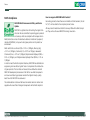
RoHS Compliance
How to recognize NEXCOM RoHS Products?
For existing products where there are non-RoHS and RoHS versions, the suffix “(LF)” will be added to the compliant product name.
NEXCOM RoHS Environmental Policy and Status
Update
All new product models launched after January 2006 will be RoHS compliant. They will use the usual NEXCOM naming convention.
NEXCOM is a global citizen for building the digital infrastructure. We are committed to providing green products
and services, which are compliant with European Union
RoHS (Restriction on Use of Hazardous Substance in Electronic Equipment)
directive 2002/95/EU, to be your trusted green partner and to protect our
environment.
RoHS restricts the use of Lead (Pb) < 0.1% or 1,000ppm, Mercury (Hg)
< 0.1% or 1,000ppm, Cadmium (Cd) < 0.01% or 100ppm, Hexavalent
Chromium (Cr6+) < 0.1% or 1,000ppm, Polybrominated biphenyls (PBB) <
0.1% or 1,000ppm, and Polybrominated diphenyl Ethers (PBDE) < 0.1% or
1,000ppm.
In order to meet the RoHS compliant directives, NEXCOM has established an
engineering and manufacturing task force in to implement the introduction
of green products. The task force will ensure that we follow the standard
NEXCOM development procedure and that all the new RoHS components
and new manufacturing processes maintain the highest industry quality
levels for which NEXCOM are renowned.
The model selection criteria will be based on market demand. Vendors and
suppliers will ensure that all designed components will be RoHS compliant.
Copyright © 2011 NEXCOM International Co., Ltd. All Rights Reserved.
v
APPC 1220T/1221T/1520T/1521T/1720T/1721T User Manual
Preface
Warranty and RMA
NEXCOM Warranty Period
have been subjected to misuse, abuse, accident, improper installation, or
usage not in accordance with the product instruction. NEXCOM assumes
no liability as a consequence of such events under the term of this warranty.
1. NEXCOM makes products in accordance with the Industry standard and,
NEXCOM warrants that all her Industry-grade IPC and System products
will be free from defect in neither material nor workmanship for twentyfour (24) months from the day of invoice issued.
2. For NEXCOM Panel PC product lines (the APPC, MPPC series), they are
also guaranteed against defect in materials and workmanship for the
period of twenty-four (24) months in their motherboard design. For 3rd
party parts, it follows with original suppliers’ standard: 12 months for
battery pack and LCD, 24 months for adaptor / add on modules (including GSM module, RFID module, and antenna).
One example is the replacement of Tablet’s or Hand-held’s LCD display
due to scratching stains or other degradation; these will not be covered
under this warranty.
2. Damages caused by customers’ delivery/shipping of the product or,
product failure resulted from electrical power/voltage shock, or, installation of parts/components which are not supplied/approved by NEXCOM
in advance.
3. Third-party products:
3. If NEXCOM determines customer’s warranty claim is valid, NEXCOM will
repair or replace product(s) without additional charge for parts and labor.
An extended Warranty Program will extend the warranty period of the
product accordingly.
Warranty Coverage
The warranty applies only to products manufactured or distributed by NEXCOM and her subsidiaries. This warranty covers all the products/shipments
except for:
a. Software, such as the device drivers,
b. External devices such as HDD, printer, scanner, mouse, LCD panel,
battery, and so on,
c. Accessory/parts that were not approved by NEXCOM and,
d. Accessory/parts were added to products after they were shipped
from NEXCOM.
1. Any claimed defect, products that have been repaired or modified by
persons who have not been authorized by NEXCOM or, products which
Copyright © 2011 NEXCOM International Co., Ltd. All Rights Reserved.
vi
APPC 1220T/1221T/1520T/1521T/1720T/1721T User Manual
Preface
3. Customers could send back the faulty product with or without the accessories and key parts such as the CPU and DIMM. If the key parts are
included, please be noted clearly within the return form. NEXCOM takes
no responsibility for the parts which are not listed in the return form.
Product will be treated as “Out of Warranty “ if:
a. It expires the warranted 24 months period from the day it was purchased.
b. It had been altered by persons other than an authorized NEXCOM service
person or, which have been subjected to misuse, abuse, accident, or
improper installation.
4. Customers hold the responsibility to ensure that the packing of defective
products is durable enough to be resistant against further damage due to
the transportation; damage caused by transportation is treated as “ Out
of Warranty “ under our Warranty specification.
c. It doesn’t have the original NEXCOM Serial Number labeling for NEXCOM’s warranty period identification or, tracking.
5. RMA product(s) returned by NEXCOM to any location other than the
customer registered delivery address will incur an extra shipping charge,
the customer is responsible for paying the extra shipping charges, duties,
and taxes of this shipment.
RMA that NEXCOM has determined not to be covered by the warranty will
be charged the NEXCOM Standard Repair Fee for the repairing. If a RMA is
determined to be not repairable, customer will be notified and product(s)
may be returned to customer at their request; a minimum service fee may be
charged however.
Product Repairing
1. NEXCOM will repair defective products covered under this limited warranty that are returned to NEXCOM; if products do prove to be defective,
they will be repaired during their warranty period unless other warranty
terms have been specified.
NEXCOM Return Merchandise Authorization (RMA) Procedure
For the RMA (Return Merchandise Authorization) shipment, customer is
responsible for packaging and shipping the product to the designated
NEXCOM service sites, with shipping charges prepaid by the customer. The
original NEXCOM shipping box should be used whenever possible. NEXCOM
shall pay for the return of the product to the customer’s location. In case of
expedited shipping request, an extra service charge shall be assessed and the
customer is responsible for this extra return shipping charge.
2. NEXCOM owns all parts removed from repaired products.
3. NEXCOM will use parts made by various manufacturers in performing the
repair.
4. The repaired products will be warranted subjected to the original warranty coverage and period only.
1. Customers should enclose the “NEXCOM RMA Service Form” with the
returned products.
5. For products returned as defective but, proved to be no defect/fault after
the RMA process, NEXCOM reserves the right to claim for a NDF (No
Defect Found) Service Charge.
2. Customers need to write down all the information related to the problem
on the “ NEXCOM RMA Service Form “ when applying for the RMA service; information will help to understand the problem, including the fault
description, on-screen messages, and pictures if possible.
Copyright © 2011 NEXCOM International Co., Ltd. All Rights Reserved.
vii
APPC 1220T/1221T/1520T/1521T/1720T/1721T User Manual
Preface
6. NEXCOM will issue RMA Report which included Repair Detailed Information to the customer when the defective products were repaired and
returned.
3. Out of Warranty “products will not be repaired without a signed PI from
the customer, the agreement of the repair process.
7. In addition to the above, NEXCOM may authorize Independent/Thirdparty suppliers to repair the defective products for NEXCOM.
Add-on card, 3rd Party Device and board level repair cost higher than
new product prices, customer can abandon to sign PI to repair and,
please contact with sales to buy new products.
Out Of Warranty Service
There will be a service charge from NEXCOM for the “Out Of Warranty”
product service; they are the Basic Diagnostic Service Fee and the Advanced
Component Replacement Fee respectively. And, if the product can not be repaired, NEXCOM will either return the product to the customer or, just scrap
it, followed by customer’s instruction.
1. Testing and Parts Replacement
NEXCOM will have the following Handling Charges for those OoW products that returned:
a. Basic Labor Cost and Testing Fee: as Table listed.
b. Parts Fee: NEXCOM will charge for main IC chipsets such as the N.B.,
S.B., Super-IO, LAN, Sound, Memory, and so on.
c. 3rd-party Device Fee: products replacement for CPU, DIMM, HDD,
Chassis, and UPS.
2. Out of Warranty product will have a three months warranty for the fixed
issues. If the product failed with different problem within 3 months, they
will still incur the service charge of “Out of Warranty”.
Copyright © 2011 NEXCOM International Co., Ltd. All Rights Reserved.
viii
APPC 1220T/1221T/1520T/1521T/1720T/1721T User Manual
Preface
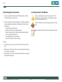
Warnings
Installation Recommendations
Read and adhere to all warnings, cautions, and notices in this guide and
the documentation supplied with the chassis, power supply, and accessory
modules. If the instructions for the chassis and power supply are inconsistent with these instructions or the instructions for accessory modules,
contact the supplier to find out how you can ensure that your computer
meets safety and regulatory requirements.
Ensure you have a stable, clean working environment. Dust and dirt can
get into components and cause a malfunction. Use containers to keep
small components separated.
Adequate lighting and proper tools can prevent you from accidentally
damaging the internal components. Most of the procedures that follow
require only a few simple tools, including the following:
Cautions
Electrostatic discharge (ESD) can damage system components. Do the described procedures only at an ESD workstation. If no such station is available, you can provide some ESD protection by wearing an antistatic wrist
strap and attaching it to a metal part of the computer chassis.
•
•
•
•
Safety Information
Using your fingers can disconnect most of the connections. It is recommended that you do not use needlenose pliers to disconnect connections
as these can damage the soft metal or plastic parts of the connectors.
Before installing and using the device, note the following precautions:
▪▪ Read all instructions carefully.
▪▪ Do not place the unit on an unstable surface, cart, or stand.
▪▪ Follow all warnings and cautions in this manual.
▪▪ When replacing parts, ensure that your service technician uses parts
specified by the manufacturer.
▪▪ Avoid using the system near water, in direct sunlight, or near a heating
device.
▪▪ The load of the system unit does not solely rely for support from the
rackmounts located on the sides. Firm support from the bottom is highly
necessary in order to provide balance stability.
▪▪ The computer is provided with a battery-powered real-time clock circuit.
There is a danger of explosion if battery is incorrectly replaced. Replace
only with the same or equivalent type recommended by the manufacturer. Discard used batteries according to the manufacturer’s instructions.
Copyright © 2011 NEXCOM International Co., Ltd. All Rights Reserved.
A Philips screwdriver
A flat-tipped screwdriver
A grounding strap
An anti-static pad
ix
APPC 1220T/1221T/1520T/1521T/1720T/1721T User Manual
Preface
Safety Precautions
12. If the equipment is not used for a long time, disconnect it from the
power source to avoid damage by transient overvoltage.
1.
2. Keep this User Manual for later reference.
13. Never pour any liquid into an opening. This may cause fire or electrical shock.
3. Disconnect this equipment from any AC outlet before cleaning. Use a
damp cloth. Do not use liquid or spray detergents for cleaning.
14. Never open the equipment. For safety reasons, the equipment should
be opened only by qualified service personnel.
4. For plug-in equipment, the power outlet socket must be located near
the equipment and must be easily accessible.
15. If one of the following situations arises, get the equipment checked
by service personnel:
5. Keep this equipment away from humidity.
a. The power cord or plug is damaged.
6. Put this equipment on a stable surface during installation. Dropping
it or letting it fall may cause damage.
b. Liquid has penetrated into the equipment.
c. The equipment has been exposed to moisture.
7.
d. The equipment does not work well, or you cannot get it to work
according to the user’s manual.
e. The equipment has been dropped and damaged.
8. The openings on the enclosure are for air convection to protect the
equipment from overheating. DO NOT COVER THE OPENINGS.
f. The equipment has obvious signs of breakage.
9. Make sure the voltage of the power source is correct before connecting the equipment to the power outlet.
17. The unit uses a three-wire ground cable which is equipped with a
third pin to ground the unit and prevent electric shock. Do not defeat
the purpose of this pin. If your outlet does not support this kind of
plug, contact your electrician to replace your obsolete outlet.
Read these safety instructions carefully.
Do not leave this equipment in either an unconditioned environment
or in a above 40oC storage temperature as this may damage the
equipment.
16. Do not place heavy objects on the equipment.
10. Place the power cord in a way so that people will not step on it. Do
not place anything on top of the power cord. Use a power cord that
has been approved for use with the product and that it matches the
voltage and current marked on the product’s electrical range label.
The voltage and current rating of the cord must be greater than the
voltage and current rating marked on the product.
18. CAUTION: DANGER OF EXPLOSION IF BATTERY IS INCORRECTLY
REPLACED. REPLACE ONLY WITH THE SAME OR EQUIVALENT TYPE
RECOMMENDED BY THE MANUFACTURER. DISCARD USED BATTERIES ACCORDING TO THE MANUFACTURER’S INSTRUCTIONS.
11. All cautions and warnings on the equipment should be noted.
Copyright © 2011 NEXCOM International Co., Ltd. All Rights Reserved.
19. The computer is provided with CD drives that comply with the appropriate safety standards including IEC 60825.
x
APPC 1220T/1221T/1520T/1521T/1720T/1721T User Manual
Preface
Technical Support and Assistance
Conventions Used in this Manual
1. For the most updated information of NEXCOM products, visit NEXCOM’s website at www.nexcom.com.
Warning: Information about certain situations, which if not
observed, can cause personal injury. This will prevent injury to
yourself when performing a task.
2. For technical issues that require contacting our technical support team
or sales representative, please have the following information ready
before calling:
Caution: Information to avoid damaging components or losing
data.
– Product name and serial number
– Detailed information of the peripheral devices
– Detailed information of the installed software (operating system,
version, application software, etc.)
– A complete description of the problem
– The exact wordings of the error messages
Note: Provides additional information to complete a task easily.
Warning!
1. Handling the unit: carry the unit with both hands and handle it with
care.
2. Maintenance: to keep the unit clean, use only approved cleaning products or clean with a dry cloth.
3. CompactFlash: Turn off the unit’s power before inserting or removing a
CompactFlash storage card.
Copyright © 2011 NEXCOM International Co., Ltd. All Rights Reserved.
xi
APPC 1220T/1221T/1520T/1521T/1720T/1721T User Manual
Preface
Global Service Contact Information
Headquarters
Taiwan
Germany
Leopoldstrase Business Centre, Leopoldstrase 244 80807
Munich, Germany
Tel: +49-89-208039-278
Fax: +49-89-208039-279
http://www.nexcom.eu
18F, No. 716, Chung-Cheng Rd., Zhonghe Dist., New Taipei City 235,
Taiwan, R.O.C.
Tel: +886-2-8228-0606
Fax: +886-2-8228-0501
http://www.nexcom.com.tw
Italy
USA
Via Gaudenzio Ferrari 29, 21047 Saronno (VA) Italia
Tel: +39 02 9628 0333
Fax: +39 02 9619 8846
http://www.nexcom.eu
3758 Spinnaker Court,
Fremont, CA 94538, USA
Tel: +1-510-656-2248
Fax: +1-510-656-2158
http://www.nexcom.com
United Kingdom
10 Vincent Avenue, Crownhill Business Centre
Milton Keynes, Buckinghamshire, MK8 0AB
United Kingdom
Tel: +44-1908-267121
Fax: +44-1908-262042
http://www.nexcom.eu
France
Z.I. des Amandiers, 17, Rue des entrepreneurs
78420 Carrières sur Seine, France
Tel: +33 (0)1 71 51 10 20
Fax: +33 (0)1 71 51 10 21
http://www.nexcom.eu
Copyright © 2011 NEXCOM International Co., Ltd. All Rights Reserved.
xii
APPC 1220T/1221T/1520T/1521T/1720T/1721T User Manual
Preface
China-Beijing
Japan
Room 301, Block E, Power Creative Building, No. 1
Shangdi East Rd. Haidian Dist., Beijing, 100085, China
Tel: +86-10-5885-6655
Fax: +86-10-5885-1066
http://www.nexcom.cn
9F, Tamachi Hara Bldg.,
4-11-5, Shiba Minato-ku Tokyo,
Japan 108-0014
Tel: +81-3-5419-7830
Fax: +81-3-5419-7832
http://www.nexcom-jp.com
China-Shanghai Office
Room 1505, Greenland He Chuang Building, No. 450
Caoyang Rd. Shanghai, 200063, China
Tel: +86-21-6150-8008
Fax: +86-21-3251-6358
http://www.nexcom.cn
China-Nanjing Office
Room 1206, Hongde Building, No. 20 Yunnan Rd.
Nanjing, 210018, China
Tel: +86-25-8324-9606
Fax: +86-25-8324-9685
http://www.nexcom.cn
China-Shenzhen Office
Western Room 708, Block 210, Tairan Industry & Trading Place,
Futian Area, Shenzhen, China 518040
TEL: +86-755-833 27203
FAX: +86-755-833 27213
http://www.nexcom.cn
Copyright © 2011 NEXCOM International Co., Ltd. All Rights Reserved.
xiii
APPC 1220T/1221T/1520T/1521T/1720T/1721T User Manual
Preface
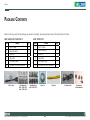
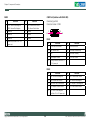
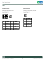
Package Contents
Before continuing, verify that the package you received is complete. Your package should have all the items listed in the table.
APPC 1220T/1221T/1520T/1521T
Item
1
Name
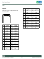
APPC 1720T/1721T
Qty
Item
1
1
PS/2 Y Cable
1
Panel Mount Kit
12
PS/2 Y Cable
Name
Qty
2
Panel Mount Kit
10
2
3
Driver CD
1
3
Driver CD
1
4
Touch Pen
1
4
Touch Pen
1
5
DC Power Cable
1
5
DC Power Cable
1
4
6
Flat Head for HDD Installation
4
6
Flat Head for HDD Installation
PS/2 Y Cable
Panel Mount Kit
APPC 1220T/1221T
APPC 1520T/1521T
Copyright © 2011 NEXCOM International Co., Ltd. All Rights Reserved.
Panel Mount Kit
APPC 1720T/1721T
Driver CD
xiv
Touch Pen
DC Power Cable
Flat Head for
HDD Installation
APPC 1220T/1221T/1520T/1521T/1720T/1721T User Manual
Preface
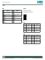
Ordering Information
The following provides ordering information for the Applied Panel PC series.
APPC 1720T (P/N: 10IA1720T00X0)
-17” TFT LED Panel PC with Intel® Atom™ D525 1.8GHz, touch screen,
1GB DDR3, COM#1/#2
• Barebone
APPC 1220T (P/N: 10IA1220T00X0)
-12.1” TFT LED Panel PC with Intel® Atom™ D525 1.8GHz, touch
screen, 1GB DDR3, COM#1/#2
APPC 1721T (P/N: 10IA1721T00X0)
-17” TFT LED Panel PC with Intel® Atom™ D525 1.8GHz, touch screen,
1GB DDR3, COM#1/#2 w/ isolation, COM#3/#4, GPIO (CAN bus optional)
APPC 1221T (P/N: 10IA1221T00X0)
-12.1” TFT LED Panel PC with Intel® Atom™ D525 1.8GHz, touch
screen, 1GB DDR3, COM#1/#2 w/ isolation, COM#3/#4, GPIO (CAN
bus optional)
• Option
12V, 60W AC/DC power adapter w/o power cord
(P/N:7400060002X00)
APPC 1520T (P/N: 10IA1520T00X0)
-15” TFT LED Panel PC with Intel® Atom™ D525 1.8GHz, touch screen,
1GB DDR3, COM#1/#2
APPC 1521T (P/N: 10IA1521T00X0)
-15” TFT LED Panel PC with Intel® Atom™ D525 1.8GHz, touch screen,
1GB DDR3, COM#1/#2 w/ isolation, COM#3/#4, GPIO (CAN bus optional)
Copyright © 2011 NEXCOM International Co., Ltd. All Rights Reserved.
xv
APPC 1220T/1221T/1520T/1521T/1720T/1721T User Manual
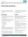
Chapter 1: Product Introduction
Chapter 1: Product Introduction
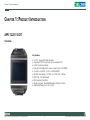
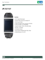
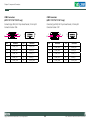
APPC 1220T/1221T
Overview
Key Features
• 4:3 12.1” Fanless LED Panel Computer
• Intel® Atom™ D525, Dual Core, Low Consumption CPU
• Full Flat 5-wire Touch Screen
• Dual GbE, 2nd Display VGA, Line-in, Line-out, Mic-in, PS/2 KB/MS
• 4 x USB, 2 x mini-PCIe, 1 x CF, 2 x RS232/422/485
• Optional Wi-Fi Module, 2.5” HDD, 2 x COMs, GPIO, CAN Bus
• DDR3 1GB, 2.5” HDD Bracket
• IP65 Compliant Front Panel
• Mounting Support: Panel/Wall/Stand/VESA 100mm x 100mm
• Wide Range Power Input: 12V~ 30V DC
Copyright © 2011 NEXCOM International Co., Ltd. All Rights Reserved.
1
APPC 1220T/1221T/1520T/1521T/1720T/1721T User Manual
Chapter 1: Product Introduction
• LED Size: 12.1”, 4:3
• Resolution: SVGA, 800x600
• Luminance: 350 cd/m2
• Contrast ratio: 300
• LCD color: 262K
• Viewing angle: 50(U), 60(D), 70(L), 70(R)
• Backlight: LED
• Touch screen: Full flat 5-wire resistive
• Touch light transmission: 80%
• Touch interface: USB
Rear I/O
• CAN BUS (optional for APPC 1221T only)
• GPIO: 4 x digital in / 4 x digital out (APPC 1221T only)
• COM1: RS232/422/485 (APPC 1221T w/ 2.5kv isolated)
• COM2: RS232/422/485 (APPC 1221T w/ 2.5kv isolated)
• COM3 and COM4: RS232 (APPC 1221T only)
• Ethernet: 2 x RJ45
• 2nd display VGA port: 1 x DB15
• Audio port: 1 x Line-out, 1 x Line-in, 1 x Mic-in
• USB: 4 x USB 2.0
• PS2 keyboard/ mouse
• Power switch
• Reset button
• CPU: Intel® Atom™ D525, 1.8GHz
• BIOS: AMI BIOS
• System chipset: Intel® ICH8M
• System memory: 1x 204-pin DDR3 SODIMM socket, 1G DDR3 (default),
Supports up to 2GB DDR3 800, Non-ECC and Unbuffered
• SSD: one external locked CF socket by IDE; supports Type I/II
CompactFlash card
• Hard drive bay: optional 2.5” SATA HDD or SATA DOM
• Watchdog timer: Watchdog timeout can be programmable by software
from 1 second to 255 seconds and from 1 minute to 255 minutes (Tolerance 15% under room temperature 25oC)
• H/W status monitor: monitors system temperature and voltage
• Expansion: 2 x mini-PCIe sockets
• NEXCOM Xcare platform system management supported
Copyright © 2011 NEXCOM International Co., Ltd. All Rights Reserved.
Audio
• AC97 codec: Realtek ALC888
• Audio interface: Line-out, Line-in and Mic-in audio jacks
Ethernet
• LAN chip: Dual Intel 82574L Gigabit LAN
• Ethernet interface: 10/100/1000 Based-Tx Ethernet compatible
Mechanical and Environment
• Color: Pantone black
• IP protection: IP65 front
• Mounting: Panel/Wall/Stand/VESA 100mm x 100mm
• Power input: 12V~30V DC
• Power adapter: Optional AC to DC power adapter (+12V, 60W)
2
APPC 1220T/1221T/1520T/1521T/1720T/1721T User Manual
Chapter 1: Product Introduction
• Vibration
- IEC 68 2-64 (w/ HDD)
- 0.5Grms @sine, 5~500Hz, 1hr/axis (HDD operating)
- 2.2Grms @ random condition, 5~500Hz, 0.5hr/axis (Non-operating)
• Shock
- IEC 68 2-27
- HDD: 20G@wall mount, half sine, 11ms
• Operating Temperature: -5°C to 50°C
• Storage temperature: -20 to 75°C
• Operating humidity: 10%~90% relative humidity, non-condensing
• Dimensions: 317 x 243 x 65mm
• Weight: 3.8kg
Certifications
• CE approval
• FCC Class A
Copyright © 2011 NEXCOM International Co., Ltd. All Rights Reserved.
3
APPC 1220T/1221T/1520T/1521T/1720T/1721T User Manual
Chapter 1: Product Introduction
APPC 1520T/1521T
Key Features
• 4:3 15” Fanless LED Panel Computer
• Intel® Atom™ D525, Dual Core, Low Consumption CPU
• Full Flat 5-wire Touch Screen
• Dual GbE, 2nd Display VGA, Line-in, Line-out, Mic-in, PS2 KB/ MS
• 4 x USB, 2 x mini-PCIe, 1 x CF, 2 x RS232/422/485
• Optional Wi-Fi Module, 2.5”HDD, 2 x COMs, GPIO, CAN Bus
• DDR3 1GB, 2.5” HDD Bracket
• IP65 Compliant Front Panel
• Mounting Support: Panel/Wall/Stand/VESA 100mm x 100mm
• Wide Range Power Input: 12V~ 30V DC
Copyright © 2011 NEXCOM International Co., Ltd. All Rights Reserved.
4
APPC 1220T/1221T/1520T/1521T/1720T/1721T User Manual
Chapter 1: Product Introduction
Specifications
Rear I/O
• CAN BUS (optional for APPC 1521T only)
• GPIO: 4 x digital in / 4 x digital out (APPC 1521T only)
• COM1: RS232/422/485 (APPC 1521T w/ 2.5kv isolated)
• COM2: RS232/422/485 (APPC 1521T w/ 2.5kv isolated)
• COM3 and COM4: RS232 (APPC 1521T only)
• Ethernet: 2 x RJ45
• 2nd display VGA port: 1 x DB15
• Audio port: 1 x Line-out, 1 x Line-in, 1 x Mic-in
• USB: 4 x USB 2.0
• PS2 keyboard/ mouse
• Power switch
• Reset button
Panel
• LED Size: 15”, 4:3
• Resolution: XGA 1024x768
• Luminance: 350cd/m2
• Contrast ratio: 500
• LCD color: 16.2M
• Viewing Angle: 65(U), 55(D), 65(L), 65(R)
• Backlight: LED
• Touch screen: Full Flat 5-wire resistive
• Touch light transmission: 80%
• Touch interface: USB
System
• CPU: Intel® Atom™ D525, 1.8GHz
• BIOS: AMI BIOS
• System chipset: Intel® ICH8M
• System memory: 1x 204-pin DDR3 SODIMM socket, 1G DDR3 (default),
Supports up to 2GB DDR3 800, Non-ECC and Unbuffered
• SSD: one external locked CF socket by IDE; supports Type I/II
CompactFlash card
• Hard drive bay: optional 2.5” SATA HDD or SATA DOM
• Watchdog timer: Watchdog timeout can be programmable by software
from 1 second to 255 seconds and from 1 minute to 255 minutes (Tolerance 15% under room temperature 25oC)
• H/W status monitor: monitors system temperature and voltage
• Expansion: 2 x mini-PCIe sockets
• NEXCOM Xcare platform system management supported
Copyright © 2011 NEXCOM International Co., Ltd. All Rights Reserved.
Audio
• AC97 codec: Realtek ALC888
• Audio interface: Line-out, Line-in, Mic-in audio jacks
Ethernet
• LAN chip: Dual Intel 82574L Gigabit LAN
• Ethernet interface: 10/100/1000 Based-Tx Ethernet compatible
Mechanical and Environment
• Color: Pantone black
• IP protection: IP65 front
• Mounting: Panel/Wall/Stand/VESA 100mm x 100mm
• Power input: 12V~30V
• Power adapter: Optional AC to DC power adapter (+12V, 60W)
5
APPC 1220T/1221T/1520T/1521T/1720T/1721T User Manual
Chapter 1: Product Introduction
• Vibration
- IEC 68 2-64 (w/ HDD)
- 0.5Grms @sine, 5~500Hz, 1hr/axis (HDD operating)
- 2.2Grms @ random condition, 5~500Hz, 0.5hr/axis (Non-operating)
• Shock
- IEC 68 2-27
- HDD: 20G@wall mount, half sine, 11ms
• Operating Temperature: -5°C to 50°C
• Storage temperature: -20 to 75°C
• Operating humidity: 10%~90% relative humidity, non-condensing
• Dimensions: 409 x 309 x 62.5mm
• Weight: 5.3kg
Certifications
• CE approval
• FCC Class A
Copyright © 2011 NEXCOM International Co., Ltd. All Rights Reserved.
6
APPC 1220T/1221T/1520T/1521T/1720T/1721T User Manual
Chapter 1: Product Introduction
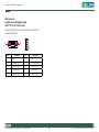
APPC 1720T/1721T
Key Features
• 4:3 17” Fanless Panel Computer
• Intel® Atom™ D525, Dual Core, Low Consumption CPU
• Flush Panel by 5-wire Touch Screen
• Dual GbE, 2nd Display VGA, Line-in, Line-out, Mic-in, PS2 KB/ MS
• 4 x USB, 2 x mini-PCIe, 1 x CF, 2 x RS232/422/485
• Optional Wi-Fi Module, 2.5”HDD, 2 x COMs, GPIO, CAN Bus
• DDR3 1GB, 2.5” HDD Bracket
• IP65 Compliant Front Panel
• Mounting Support: Panel/Wall/Stand/VESA 100mm x 100mm
• Wide Range Power Input: 12V~ 30V DC
Copyright © 2011 NEXCOM International Co., Ltd. All Rights Reserved.
7
APPC 1220T/1221T/1520T/1521T/1720T/1721T User Manual
Chapter 1: Product Introduction
Specifications
Rear I/O
• CAN BUS (optional for APPC 1721T only)
• GPIO: 4 x digital in / 4 x digital out (APPC 1721T only)
• COM1: RS232/422/485 (APPC 1721T w/ 2.5kv isolated)
• COM2: RS232/422/485 (APPC 1721T w/ 2.5kv isolated)
• COM3 and COM4: RS232 (APPC 1721T only)
• Ethernet: 2 x RJ45
• 2nd display VGA port: 1 x DB15
• Audio port: 1 x Line-out; 1 x Line-in; 1 x Mic-in
• USB: 4 x USB 2.0
• PS2 keyboard/ mouse
• Power switch
• Reset button
Panel
• LED Size: 17”, 4:3
• Resolution: SXGA 1280x1024
• Luminance: 380cd/m2
• Contrast ratio: 1000
• LCD color: 16.7M
• Viewing Angle: 80(U), 80(D), 85(L), 85(R)
• Backlight: CCFL
• Touch screen: 5-wire resistive (flush panel type)
• Touch light transmission: 81%
• Touch interface: USB
System
• CPU: Intel® Atom™ D525, 1.8GHz
• BIOS: AMI BIOS
• System chipset: Intel® ICH8M
• System memory: 1x 204-pin DDR3 SODIMM socket, 1G DDR3 (default),
Supports up to 2GB DDR3 800, Non-ECC and Unbuffered
• SSD: one external locked CF socket by IDE; supports Type I/II
CompactFlash card
• Hard drive bay: optional 2.5” SATA HDD or SATA DOM
• Watchdog timer: Watchdog timeout can be programmable by software
from 1 second to 255 seconds and from 1 minute to 255 minutes (Tolerance 15% under room temperature 25oC)
• H/W status monitor: monitors system temperature and voltage
• Expansion: 2 x mini-PCIe sockets
• NEXCOM Xcare platform system management supported
Copyright © 2011 NEXCOM International Co., Ltd. All Rights Reserved.
Audio
• AC97 codec: Realtek ALC888
• Audio interface: Line-out, Line-in, Mic-in audio jacks
Ethernet
• LAN chip: Dual Intel 82574L Gigabit LAN
• Ethernet interface: 10/100/1000 Based-Tx Ethernet compatible
Mechanical and Environment
• Color: Pantone black
• IP protection: IP65 front
• Mounting: Panel/Wall/Stand/VESA 100mm x 100mm
• Power input: 12V~30V
• Power adapter: Optional AC to DC power adapter (+12V, 60W)
8
APPC 1220T/1221T/1520T/1521T/1720T/1721T User Manual
Chapter 1: Product Introduction
• Vibration
- IEC 68 2-64 (w/ HDD)
- 0.5Grms @sine, 5~500Hz, 1hr/axis (HDD operating)
- 2.2Grms @ random condition, 5~500Hz, 0.5hr/axis (Non-operating)
• Shock
- IEC 68 2-27
- HDD: 20G@wall mount, half sine, 11ms
• Operating Temperature: -5°C to 50°C
• Storage temperature: -20 to 75°C
• Operating humidity: 10%~90% relative humidity, non-condensing
• Dimensions: 410.4 x 340.4 x 75.79mm
• Weight: 6.3 kg
Certifications
• CE approval
• FCC Class A
Copyright © 2011 NEXCOM International Co., Ltd. All Rights Reserved.
9
APPC 1220T/1221T/1520T/1521T/1720T/1721T User Manual
Chapter 1: Product Introduction
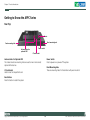
Getting to Know the APPC Series
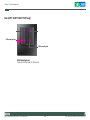
Rear Top
Reset
Panel mounting hole
Panel mounting hole
Antenna holes for
optional WiFi
Power switch
CF card socket
Power Switch
Press to power-on or power-off the system.
Antenna Holes for Optional WiFi
The 2 external antenna mounting holes are used to mount and connect
optional WiFi antennas.
Panel Mounting Hole
These are mounting holes for Panel Mount with panel mount kit.
CF Card Socket
Used to insert a CompactFlash card.
Reset Button
Press this button to restart the system.
Copyright © 2011 NEXCOM International Co., Ltd. All Rights Reserved.
10
APPC 1220T/1221T/1520T/1521T/1720T/1721T User Manual
Chapter 1: Product Introduction
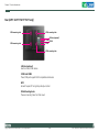
Rear Bottom
Line-out
PS/2 KB/MS
Line-in
Mic-in
LAN1 USB COM1
VGA
COM2 12V-30V
LAN2
DC Input
Used to connect an audio device, such as a CD player.Used to connect a
headphone or a speaker.
Used to connect an external microphone.
Used to connect the system to a local area network.
Used to connect USB 2.0/1.1 devices.
These COM ports support RS232/422/485 compatible serial devices. APPC
1221T/1521T/1721T are with 2.5kV isolation.
Used to connect a PS/2 keyboard and a PS/2 mouse via a cable.
Used to connect an analog VGA monitor.
Used to plug a DC power cord.
Copyright © 2011 NEXCOM International Co., Ltd. All Rights Reserved.
11
APPC 1220T/1221T/1520T/1521T/1720T/1721T User Manual
Chapter 1: Product Introduction
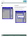
Rear (APPC 1220T/1520T/1720T only)
VESA mounting hole
VESA mounting hole
VESA Mounting Holes
These are mounting holes for VESA mount.
Copyright © 2011 NEXCOM International Co., Ltd. All Rights Reserved.
12
APPC 1220T/1221T/1520T/1521T/1720T/1721T User Manual
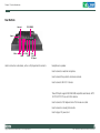
Chapter 1: Product Introduction
Rear (APPC 1221T/1521T/1721T only)
VESA mounting hole
VESA mounting hole
COM3
VESA mounting hole
GPIO
CAN bus (optional)
COM4
VESA mounting hole
CAN Bus (optional)
Used to connect CAN devices.
COM3 and COM4
These COM ports support RS232 compatible serial devices.
GPIO
General Purpose I/O for digital input/output control.
VESA Mounting Holes
These are mounting holes for VESA mount.
Copyright © 2011 NEXCOM International Co., Ltd. All Rights Reserved.
13
APPC 1220T/1221T/1520T/1521T/1720T/1721T User Manual
Chapter 1: Product Introduction
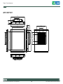
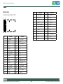
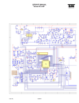
Mechanical Dimensions
APPC 1220T/1221T
299,50
134,45
RESET
45,50
10,20
65,00
317,00
8,00
246,00
270,00
28,00
100,00
28,55
243,00
183,30 225,65
173,90
100,00
184,50
1
2
COM1
COM2
DC IN 12V~30V
Copyright © 2011 NEXCOM International Co., Ltd. All Rights Reserved.
14
APPC 1220T/1221T/1520T/1521T/1720T/1721T User Manual
Chapter 1: Product Introduction
APPC 1520T/1521T
389,50
134,45
RESET
43,00
9,50
409,00
270,00
62,50
334,70
25,50
100,00
6,20
181,90
309,00
257,60
173,90
100,00
289,50
1
2
COM1
COM2
DC IN 12V~30V
Copyright © 2011 NEXCOM International Co., Ltd. All Rights Reserved.
15
APPC 1220T/1221T/1520T/1521T/1720T/1721T User Manual
Chapter 1: Product Introduction
APPC 1720T/1721T
392,40
134,45
RESET
56,40
11,80
75,79
410,42
270,00
38,90
338,92
100,00
6,00
173,90
181,90
340,42
271,34
322,38
1
2
COM1
COM2
DC IN 12V~30V
Copyright © 2011 NEXCOM International Co., Ltd. All Rights Reserved.
100,00
16
APPC 1220T/1221T/1520T/1521T/1720T/1721T User Manual
Chapter 2: Jumpers and Connectors
Chapter 2: Jumpers and Connectors
tronic components. Humid environment tend to have less static electricity than dry environments. A grounding strap is warranted whenever
danger of static electricity exists.
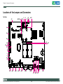
This chapter describes the jumpers and connectors on the motherboard.
Note that information in this chapter applies to APPC 1220T/1221T/1520T/
1521T/1720T/1721T.
Before You Begin
Precautions
• Ensure you have a stable, clean working environment. Dust and dirt can
Computer components and electronic circuit boards can be damaged by
discharges of static electricity. Working on the computers that are still connected to a power supply can be extremely dangerous.
get into components and cause a malfunction. Use containers to keep
small components separated.
Follow the guidelines below to avoid damage to your computer or yourself:
• Adequate lighting and proper tools can prevent you from accidentally
damaging the internal components. Most of the procedures that follow
require only a few simple tools, including the following:
• Always disconnect the unit from the power outlet whenever you are
working inside the case.
• A Philips screwdriver
• A flat-tipped screwdriver
• If possible, wear a grounded wrist strap when you are working inside
• A set of jewelers Screwdrivers
the computer case. Alternatively, discharge any static electricity by
touching the bare metal chassis of the unit case, or the bare metal body
of any other grounded appliance.
• A grounding strap
• An anti-static pad
• Using your fingers can disconnect most of the connections. It is recom-
• Hold electronic circuit boards by the edges only. Do not touch the com-
mended that you do not use needle-nosed pliers to disconnect connections as these can damage the soft metal or plastic parts of the connectors.
ponents on the board unless it is necessary to do so. Don’t flex or stress
the circuit board.
• Leave all components inside the static-proof packaging that they
• Before working on internal components, make sure that the power
shipped with until they are ready for installation.
is off. Ground yourself before touching any internal components, by
touching a metal object. Static electricity can damage many of the elec-
Copyright © 2011 NEXCOM International Co., Ltd. All Rights Reserved.
• Use correct screws and do not over tighten screws.
17
APPC 1220T/1221T/1520T/1521T/1720T/1721T User Manual
Chapter 2: Jumpers and Connectors
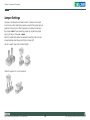
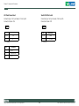
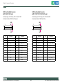
Jumper Settings
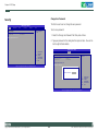
A jumper is the simplest kind of electric switch. It consists of two metal
pins and a cap. When setting the jumpers, ensure that the jumper caps are
placed on the correct pins. When the jumper cap is placed on both pins,
the jumper is short. If you remove the jumper cap, or place the jumper
cap on just one pin, the jumper is open.
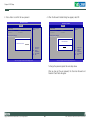
Refer to the illustrations below for examples of what the 2-pin and 3-pin
jumpers look like when they are short (on) and open (off).
Two-Pin Jumpers: Open (Left) and Short (Right)
Three-Pin Jumpers: Pins 1 and 2 Are Short
Copyright © 2011 NEXCOM International Co., Ltd. All Rights Reserved.
18
APPC 1220T/1221T/1520T/1521T/1720T/1721T User Manual
Chapter 2: Jumpers and Connectors
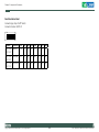
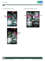
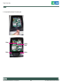
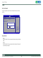
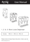
Locations of the Jumpers and Connectors
Top View
J1
SWITCH1
J3
JP1
JP4 JP2
CON1
6
JP3
1
1
FAN1
1
JP4
1
3
JP1
2
1
JP2
H2
H1
2
3
1
4
1
J1
C10
C7
C8
C9
CON1
R8
3
1
BAT1
1
7
BAT1
20
R9
JP5
B
E
R17
R18
19
J3
C
B
Q3
R534
C15
E
CN1
H3
Q4
C
C37
C39
C40
C29
C30
A
U5
C49
C48
9
8
16
15
7
14
13
5
4
6
3
12
11
10
2
2
1
1
C28
C27
R24
H6
D
E
20
F
G
H
CN2
J
K
P
N M L
K J
H G
F E
U8
D C B A
L
SW1
M
1
R
P
2
R123
R118
R114
R108
R105
R103
10
12
R135
R132
20
R
T
U
J
V
AP-D525-D
G
F
E
D
C
B
A
8
9
11
19
P
M
L
K
6
7
H
2
N
N
3
4
5
1
13
14
9 8 7
REV:C
W
Y
4BI0D525A2X10
RN5
AA
AB
MADE IN TAIWAN
AC
R765
R766
R767
3 2 1
2
1
R
C90
CN2
T
C84
AL
AK
AJ
AH
AG
AE
AD
AC
AB
AA
Y
W
V
T
P
N
M
L
K
J
H
G
F
E
D
C
B
A
C
R70
R71
R72
R73
R74
R75
R76
RN3
R77
C59
R78
R79
R80
RN4
R81
R69
C57
C58
C55
C56
RN2
R64
R65
R66
R67
R68
RN1
R61
R62
R63
B
19
AD
AE
H8
AF
16
AG
AH
CN3
AJ
BZ1
RN8
C163
C
2
R227
R228
H9
1
CN4
M9
51
G
17
15
1
CN4
51
JP6
3
JP6
J4
J4
6
5
1
39
64
3
65
CN5
38
52
18
16
2
52
18
16
2
1
1
JP7
J5
JP8
C162
Q8
CN3
C155
9
6
J5
J6
MH3
MH4
102
1
1
1
R477
1
C351
C380
CN6
J10
JP9
10
1
2
9
1
C374
2
10
1
9
G
H12
10
2
U40
C373
2
1
CN7
5
C359
9
S
11
U39
L10
C381
7
8
JP9
J10
MH5
MH5
MH6
1
MH6
J7
J8
MH4
L7
1
128
103
2
J9
1
9
H
C418
H13
4
5
8
1
4
1
2
FB43
8
COM1
5
1
COM2
4
6
5
3
1
CN10
15
1
16
2
4
9
6
9
KM1
6
6
5
LAN1
LAN2
USB1
USB2
COM1
COM2
J9
Copyright © 2011 NEXCOM International Co., Ltd. All Rights Reserved.
19
KM1
CN6
5
11
15
CN9
2
3
1
1
USB2
7
LAN2
LAN1
1
USB1
CN9
2
7
5
8
5
2
8
CN8
3
8
FB42
2
6
G
H11
5
1
1
VGA1
CN7
CN8
APPC 1220T/1221T/1520T/1521T/1720T/1721T User Manual
Chapter 2: Jumpers and Connectors
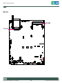
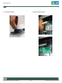
Bottom View
1
4
1
3
1
2
2
1
C448
R543
C449
C450
C452
C451
204
C453
1
6
4
R545
C454
1
1
C455
C456
C457
R541
R542
1
C458
3
C459
3
1
DIMM1
74
2
72
DDR3 SODIMM
R544
73
71
1
203
R550
C471
C464
C468
C466
C465
C469
C467
C470
CF card socket
50
25
26
C515
3
6
5
1
3
1
1
1
9
6
C613
C614
C612
R657
1
1
7
8
1
C659
10
2
9
10
2
1
C660
9
1
2
1
C665
5
8
5
8
1
4
1
4
1
11
10
9
12
11
10
9
8
R727
CP8
R726
R725
CP7
5
R721
CP6
R732
7
R733
1
R736
7
R735
1
4
R734
2
8
R737
2
R738
8
R719
R720
CP5
1
2
6
2
5
1
3
5
1
15
12
16
3
1
1
6
2
2
3
4
12 8
3
9
6
1
14 10
9
6
6
5
5
15
11
2
13 9
4
20
7
Copyright © 2011 NEXCOM International Co., Ltd. All Rights Reserved.
5
APPC 1220T/1221T/1520T/1521T/1720T/1721T User Manual
Chapter 2: Jumpers and Connectors
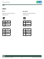
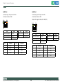
Jumpers
RTC Clear
Power Type Select
Connector type:1x3 3-pin header, 2.54 mm pitch
Connector location: JP4
Connector type: 1x3 3-pin header, 2.54 mm pitch
Connector location: JP5
3
1
Pin
Settings
1-2 On
Normal
2-3 On
CMOS Clear
Pin
1-2 On: default
Pin
3
1
Definition
1-2 On
AT Mode
2-3 On
ATX Mode
2-3 On: default
Definition
Pin
Definition
1
NC
1
AUTO (AT MODE)
2
RTC Power
2
PWRBT In
3
GND
3
Manual ( ATX MODE)
Copyright © 2011 NEXCOM International Co., Ltd. All Rights Reserved.
21
APPC 1220T/1221T/1520T/1521T/1720T/1721T User Manual
Chapter 2: Jumpers and Connectors
LCD Panel Power Select
Touch 4/5/8 Wire Select
Connector type: 1x3 3-pin header, 2.54 mm pitch
Connector location: JP6
Connector type: 1x3 3-pin header, 2.54 mm pitch
Connector location: JP8
3
1
3
1
Pin
Definition
1-2 On
3.3V
1-2 On
5 wire
2-3 On
5V
2-3 On
4/8 wire
1-2 On: default
Pin
1-2 On: default
Definition
1
VCC3
2
Power for VDD
3
VCC5
Copyright © 2011 NEXCOM International Co., Ltd. All Rights Reserved.
22
APPC 1220T/1221T/1520T/1521T/1720T/1721T User Manual
Chapter 2: Jumpers and Connectors
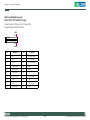
Panel Resolution Select
1
2
3
4
5
6
7
8
O
N
Connector type: 8-pin On/Off Switch
Connector location: SWITCH1
SW2
SW3
SW4
SW5
SW6
SW7
SW8
APPC1220T
APPC1221T
Model
Resolution
800x600
SW1
ON
ON
ON
OFF
OFF
OFF
OFF
OFF
APPC1520T
APPC1521T
1024x768
OFF
OFF
ON
OFF
ON
ON
OFF
OFF
APPC1720T
APPC1721T
1280x1024
OFF
OFF
OFF
OFF
ON
ON
ON
OFF
Copyright © 2011 NEXCOM International Co., Ltd. All Rights Reserved.
23
APPC 1220T/1221T/1520T/1521T/1720T/1721T User Manual
Chapter 2: Jumpers and Connectors
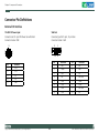
Connector Pin Definitions
External I/O Interface
12V-30V DC Power Input
VGA Port
Connector size: DC 4-pin DIN Power Jack with Shield
Connector location: CN8
Connector type: DB-15 port, 15-pin D-Sub
Connector location: VGA1
5
2
4
1
3
Pin
DC+
2
DC+
3
DC-
4
DC-
5
GND
Copyright © 2011 NEXCOM International Co., Ltd. All Rights Reserved.
1
15
11
Pin
Definition
1
5
1
24
Definition
Pin
Definition
Red
9
+5V
2
Green
10
GND
3
Blue
11
N/C
4
N/C
12
DDC Data
5
GND
13
HSYNC
6
GND
14
VSYNC
7
GND
15
DDC Clock
8
GND
16
N/C
APPC 1220T/1221T/1520T/1521T/1720T/1721T User Manual
Chapter 2: Jumpers and Connectors
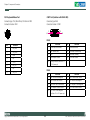
PS/2 Keyboard/Mouse Port
COM1 Port (Isolation with RS422/485)
Connector type: PS/2, Mini-DIN-6, JST-2.0mm-M-180
Connector location: KM1
Connector type: DB-9
Connector location: COM1
6
3
8
5
2 1
Pin
1
6
5
9
RS232
Pin
Definition
1
KB_DATA
2
MS_DATA
3
GND
4
NC
5
VCC5
6
KB_CLK
7
NC
8
MS_CLK
1
Pin
2
Definition
RXD#: Receive Data
3
TXD: Transmit Data
4
DTR#: Data Terminal Ready
5
GND
6
DSR#: Data Set Ready
7
RTS#: Request To Send
8
CTS#: Clear To Send
9
RI#: Ring Indicator (could be a 5V
or 12V power pin)
RS422
Pin
1
Copyright © 2011 NEXCOM International Co., Ltd. All Rights Reserved.
Definition
DCD#: Data Carrier Detect
25
Definition
TXD-: Transmit Data Negative
Pin
2
Definition
TXD+: Transmit Data Positive
3
RXD+: Receive Data Positive
4
RXD-: Receive Data Negative
5
GND DCD#: Data Carrier Detect
6
RTS-: Request To Send Negative
7
RTS+: Request To Send Positive
8
CTS+: Clear to Send Positive
9
CTS-: Clear To Send Negative
(could be a 5V or 12V power pin)
APPC 1220T/1221T/1520T/1521T/1720T/1721T User Manual
Chapter 2: Jumpers and Connectors
RS485
COM2 Port (Isolation with RS422/485)
Pin
Definition
Pin
Connector type: DB-9
Connector location: COM2
Definition
1
TXD-: Transmit Data Negative
RXD-: Receive Data Negative
2
TXD+: Transmit Data Positive
RXD+: Receive Data Positive
3
Reserved
4
Reserved
5
Reserved
6
Reserved
7
Reserved
8
Reserved
9
Reserved (could be a 5V or 12V
power pin)
1
6
5
9
RS232
Pin
1
Definition
DCD#: Data Carrier Detect
Pin
2
Definition
RXD#: Receive Data
3
TXD: Transmit Data
4
DTR#: Data Terminal Ready
5
GND
6
DSR#: Data Set Ready
7
RTS#: Request To Send
8
CTS#: Clear To Send
9
RI#: Ring Indicator (could be a 5V
or 12V power pin)
RS422
Pin
1
Copyright © 2011 NEXCOM International Co., Ltd. All Rights Reserved.
26
Definition
TXD-: Transmit Data Negative
Pin
2
Definition
TXD+: Transmit Data Positive
3
RXD+: Receive Data Positive
4
RXD-: Receive Data Negative
5
GND DCD#: Data Carrier Detect
6
RTS-: Request To Send Negative
7
RTS+: Request To Send Positive
8
CTS+: Clear to Send Positive
9
CTS-: Clear To Send Negative
(could be a 5V or 12V power pin)
APPC 1220T/1221T/1520T/1521T/1720T/1721T User Manual
Chapter 2: Jumpers and Connectors
RS485
USB Ports
Pin
Definition
Pin
Connector type: Dual USB port
Connector location: USB1 and USB2
Definition
1
TXD-: Transmit Data Negative
RXD-: Receive Data Negative
2
TXD+: Transmit Data Positive
RXD+: Receive Data Positive
3
Reserved
4
Reserved
5
Reserved
6
Reserved
7
Reserved
8
Reserved
9
Reserved (could be a 5V or 12V
power pin)
USB1
Pin
Definition
Pin
Definition
1
VCC5
5
VCC5
2
USB0-
6
USB1-
3
USB0+
7
USB1+
4
GND
8
GND
USB2
Pin
Copyright © 2011 NEXCOM International Co., Ltd. All Rights Reserved.
27
Definition
Pin
Definition
1
VCC5
5
VCC5
2
USB2-
6
USB3-
3
USB2+
7
USB3+
4
GND
8
GND
APPC 1220T/1221T/1520T/1521T/1720T/1721T User Manual
Chapter 2: Jumpers and Connectors
LAN1 Port
LAN2 Port
Connector type: RJ45 port with LEDs
Connector location: LAN1
Connector type: RJ45 port with LEDs
Connector location: LAN2
Link
Note: LAN2 supports Wake On LAN (WOL)
Act
Link
Act
Status
Green Always Lighted
Link
1000M
Orange Blinking
Data Activity
Orange Always Lighted
100M
Off
No Acitivity
Off
10M or No Link
Pin
Status
Definition
Pin
Act
Link
Status
Act
Status
Green Always Lighted
1000M
Orange Blinking
Data Activity
Orange Always Lighted
100M
Off
No Acitivity
Off
10M or No Link
Definition
1
MDI0+
5
MDI2-
Pin
2
MDI0-
6
MDI1-
1
MDI0+
5
MDI2-
3
MDI1+
7
MDI3+
2
MDI0-
6
MDI1-
4
MDI2+
8
MDI3-
3
MDI1+
7
MDI3+
4
MDI2+
8
MDI3-
Copyright © 2011 NEXCOM International Co., Ltd. All Rights Reserved.
28
Definition
Pin
Definition
APPC 1220T/1221T/1520T/1521T/1720T/1721T User Manual
Chapter 2: Jumpers and Connectors
Line-out Jack
Connector type: 1x5 5-pin header, 2.0 mm pitch
Connector location: CN9
Pin
Definition
1
LOUT_R
2
JD
3
NC
4
LOUT_L
5
GND
6
GND
Copyright © 2011 NEXCOM International Co., Ltd. All Rights Reserved.
29
APPC 1220T/1221T/1520T/1521T/1720T/1721T User Manual
Chapter 2: Jumpers and Connectors
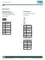
Internal Connectors
Xilinx Programming Connector
(APPC 1720T/1721T/1520T/1521T only)
Panel Backlight Connector
Connector size: 1x6 6-pin JST, 2.54 mm pitch
Connector location: J4
Connector type: 1x6 6-pin header, 2.54 mm pitch
Connector location: JP7
1
6
1
Pin
6
Definition
1
VCC3
2
GND
Pin
Definition
3
TCK
1
BKCTRL
4
TDO
2
GND
5
TDI
3
12V
TMS
4
GND
5
BKLEN
6
VCC5
6
Pin 1 BKCTRL Functional Status
Copyright © 2011 NEXCOM International Co., Ltd. All Rights Reserved.
30
Percentage
Voltage Level
100%
3.4V
80%
2.7V
60%
1.9V
40%
1.1V
APPC 1220T/1221T/1520T/1521T/1720T/1721T User Manual
Chapter 2: Jumpers and Connectors
LVDS Panel Backlight Connector
(APPC 1220T/1221T only)
LVDS Panel Backlight Connector
(APPC 1720T/1721T/1520T/1521T only)
Connector type: 2x10 20-pin, LCD-1.25mm-M-180
Connector location: CN1 (from Pineview)
Connector type: 2x10 20-pin, LCD-1.25mm-M-180
Connector location: CN2 (from Xilinx)
MH1
MH1
1
19
1
19
2
20
2
20
MH2
Pin
Definition
MH2
Pin
Definition
Pin
Definition
Pin
Definition
1
NC
11
RXCLK+
1
NC
11
RXCLK+ (ODD)
2
NC
12
RX1-
2
NC
12
RX1- (ODD)
3
VDD
13
RXCLK-
3
VDD
13
RXCLK- (ODD)
4
RX0+
14
GND
4
RX0+ (ODD)
14
GND
5
NC
15
GND
5
RX3+ (ODD)
15
GND
6
RX0-
16
12V
6
RX0- (ODD)
16
12V
7
NC
17
RX2+
7
RX3- (ODD)
17
RX2+ (ODD)
8
VDD
18
12V
8
VDD
18
12V
9
GND
19
RX2-
9
GND
19
RX2- (ODD)
10
RX1+
20
GND
10
RX1+ (ODD)
20
GND
Copyright © 2011 NEXCOM International Co., Ltd. All Rights Reserved.
31
APPC 1220T/1221T/1520T/1521T/1720T/1721T User Manual
Chapter 2: Jumpers and Connectors
LVDS Panel Backlight Connector
(APPC 1720T/1721T/1520T/1521T only)
Connector type: 2x10 20-pin, LCD-1.25mm-M-180
Connector location: CN3 (from Xilinx)
MH1
1
19
2
20
MH2
Pin
Definition
Pin
Definition
1
NC
11
RXCLK+ (EVEN)
2
NC
12
RX1- (EVEN)
3
VDD
13
RXCLK- (EVEN)
4
RX0+ (EVEN)
14
GND
5
RX3+ (EVEN)
15
GND
6
RX0- (EVEN)
16
12V
7
RX3+ (EVEN)
17
RX2+ (EVEN)
8
VDD
18
12V
9
GND
19
RX2- (EVEN)
10
RX1+ (EVEN)
20
GND
Copyright © 2011 NEXCOM International Co., Ltd. All Rights Reserved.
32
APPC 1220T/1221T/1520T/1521T/1720T/1721T User Manual
Chapter 2: Jumpers and Connectors
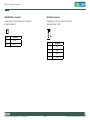
Power Button Connector
Reset Button
Connector type:1x2 2-pin header, JST 2.0 mm pitch
Connector location: J7
Connector type:1x2 2-pin header, 2.0 mm pitch
Connector location: J8
1
1
2
Pin
Definition
2
Pin
Definition
1
PWRBT
1
PWRBT
2
GND
2
GND
Copyright © 2011 NEXCOM International Co., Ltd. All Rights Reserved.
33
APPC 1220T/1221T/1520T/1521T/1720T/1721T User Manual
Chapter 2: Jumpers and Connectors
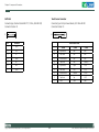
SATA DOM Power Connector
SATA Power Connector
Connector type:1x2 2-pin header, JST 2.0 mm pitch
Connector location: J1
Connector type: 1x4 4-pin Wafer, 2.54 mm pitch
Connector location: CON1
1
1
2
Pin
4
Definition
1
PWRBT
2
GND
Copyright © 2011 NEXCOM International Co., Ltd. All Rights Reserved.
Pin
34
Definition
1
+12V
2
GND
3
GND
4
VCC5
APPC 1220T/1221T/1520T/1521T/1720T/1721T User Manual
Chapter 2: Jumpers and Connectors
SATA Port
Touch Sensor Connector
Connector type: Standard Serial ATAII 7P (1.27mm, SATA-M-180)
Connector location: J3
Connector type:1x9 9-pin boxed header, JST-2.0mm-M-180
Connector location: J5
7
1
1
9
Pin
Definition
1
GND
2
TX+
9
Right Sense
N/A
N/A
3
TX-
8
Left Sense
N/A
N/A
4
GND
7
Bottom Sense
N/A
N/A
5
RX-
6
Top Sense
N/A
Sense (S)
6
RX+
5
Right Excite
Right
LR (X)
7
GND
4
Left Excite
Left
LL (L)
3
Bottom Excite
Bottom
UR (H)
2
Top Excite
Top
UL (Y)
1
GND
GND
GND
Copyright © 2011 NEXCOM International Co., Ltd. All Rights Reserved.
Touch Screen Lines
8-Wire
35
4-Wire
5-Wire
APPC 1220T/1221T/1520T/1521T/1720T/1721T User Manual
Chapter 2: Jumpers and Connectors
USB Connector
Connector size: 1x6 6-pin JST wafer, 2.54 mm pitch
Connector location: J6
6
1
Pin
Definition
1
+5V
2
USB4-
3
USB4+
4
USB5-
5
USB5+
6
GND
Copyright © 2011 NEXCOM International Co., Ltd. All Rights Reserved.
36
APPC 1220T/1221T/1520T/1521T/1720T/1721T User Manual
Chapter 2: Jumpers and Connectors
CompactFlash
Pin
Description
Pin
Connector type: 1x50 50-pin with Ejector, CompactFlash Type 2
Connector location: IDE1
15
GND
40
N/C
Pin
Description
16
GND
41
CF_RESET#
17
GND
42
+3.3V
18
PDAddress2
43
PDDREQ
19
PDAddress1
44
PDDACK
20
PDAddress0
45
IDE_ACT#
21
PDData0
46
N/C
22
PDData1
47
PD Data8
23
PDData2
48
PD Data9
Description
Pin
Description
24
N/C
49
PD Data10
1
GND
26
CF_DETECT
25
GND
50
GND
2
PD Data3
27
PD Data11
3
PD Data4
28
PD Data12
4
PD Data5
29
PD Data13
5
PD Data6
30
PD Data14
6
PD Data7
31
PD Data15
7
-PCS0
32
-PCS1
8
GND
33
N/C
9
GND
34
-PDIOR
10
GND
35
-PDIOW
11
GND
36
+5V
12
GND
37
IRQ14
13
+5V
38
+5V
14
GND
39
GND
Copyright © 2011 NEXCOM International Co., Ltd. All Rights Reserved.
37
APPC 1220T/1221T/1520T/1521T/1720T/1721T User Manual
Chapter 2: Jumpers and Connectors
Power LED Connector
Connector type:1x2 2-pin header, 2.54 mm pitch
Connector location: JP1
Connector type:1x2 2-pin header, 2.54 mm pitch
Connector location: JP2
2
1
Pin
2
1
Definition
Pin
Definition
1
+5V
1
+5V
2
GND
2
HD_LED#
Copyright © 2011 NEXCOM International Co., Ltd. All Rights Reserved.
38
APPC 1220T/1221T/1520T/1521T/1720T/1721T User Manual
Chapter 2: Jumpers and Connectors
Mini-PCIe Slots
Pin
Connector location: CN4 and CN5
31
PCIE_TX2N
1
51
2
52
Pin
Definition
Pin
Definition
1
WAKE0#
2
+V3.3_MINI
3
NC
4
GND
5
NC
6
+V1.5S_MINI
7
NC
8
NC
9
GND
10
NC
11
GPP_CLK0_N
12
NC
13
GPP_CLK0_P
14
NC
15
GND
16
NC
17
NC
18
GND
19
NC
20
MINICARD1_DIS#
21
GND
22
PCIE_RST#
23
PCIE_RX2N
24
+V3.3A_MINI
25
PCIE_RX2P
26
GND
27
GND
28
+V1.5S_MINI
29
GND
30
SMB_CLK
Copyright © 2011 NEXCOM International Co., Ltd. All Rights Reserved.
39
Definition
Pin
32
Definition
SMB_DAT
33
PCIE_TX2P
34
GND
35
GND
36
USB_6N
37
GND
38
USB_6P
39
+V3.3A_MINI
40
GND
41
+V3.3A_MINI
42
NC
43
GND
44
NC
45
NC
46
NC
47
NC
48
+V1.5S_MINI
49
NC
50
GND
51
NC
52
+V3.3A_MINI
APPC 1220T/1221T/1520T/1521T/1720T/1721T User Manual
Chapter 2: Jumpers and Connectors
COM3 Connectors
(APPC 1721T/1521T/1221T only)
COM4 Connectors
(APPC 1721T/1521T/1221T only)
Connector type:DB-9; 2x5 10-pin boxed header, 2.0 mm pitch
Connector location: CN6
Connector type:DB-9; 2x5 10-pin boxed header, 2.0 mm pitch
Connector location: CN7
6
1
5
2
1
9
10
9
6
1
5
2
1
9
10
9
Pin
Definition
Pin
Definition
Pin
Definition
Pin
1
COM3_DCD
6
COM3_DSR
1
COM4_DCD
6
COM4_DSR
2
COM3_RXD
7
COM3_RTS
2
COM4_RXD
7
COM4_RTS
3
COM3_TXD
8
COM3_CTS
3
COM4_TXD
8
COM4_CTS
4
COM3_DTR
9
COM3_RI
4
COM4_DTR
9
COM4_RI
5
COM3_GND
10
COM3_GND
5
COM4_GND
10
COM4_GND
Copyright © 2011 NEXCOM International Co., Ltd. All Rights Reserved.
40
Definition
APPC 1220T/1221T/1520T/1521T/1720T/1721T User Manual
Chapter 2: Jumpers and Connectors
GPIO Connector
4 digital input and 4 digital output
(APPC 1721T/1521T/1221T only)
Connector type:DB-15; 2x5 10-pin header, 2.0 mm-M-180
Connector location: J9
6
1
5
Pin
1
2
9
10
10
Definition
Pin
Definition
1
+5V
2
GND
3
GPIO24 (GPO)
4
GPIO20 (GPI)
5
GPIO25 (GPO)
6
GPIO21 (GPI)
7
GPIO26 (GPO)
8
GPIO22 (GPI)
9
GPIO27 (GPO)
10
GPIO23 (GPI)
Copyright © 2011 NEXCOM International Co., Ltd. All Rights Reserved.
41
APPC 1220T/1221T/1520T/1521T/1720T/1721T User Manual
Chapter 2: Jumpers and Connectors
Line-in/Mic-in Connector
Speaker-out Connector
Connector type:2x4 8-pin header, 2.54 mm
Connector location: JP9
Connector type: 1x4 4-pin header, 2.54 mm pitch
Connector location: J10
2
1
Line-in
Pin
Pin
Mic-in
Definition
4
1
8
7
Pin
Definition
1
OUT-L+
Definition
2
OUT-L-
1
LINE IN-LP
2
MIC1_L3
3
OUT-R+
3
LINE IN -JD
4
MIC_JD
4
OUT-R-
5
GND
6
GND
7
LINE IN-RP
8
MIC1_R3
Copyright © 2011 NEXCOM International Co., Ltd. All Rights Reserved.
42
APPC 1220T/1221T/1520T/1521T/1720T/1721T User Manual
Chapter 2: Jumpers and Connectors
Block Diagram
APPC 1720T/1520T
Copyright © 2011 NEXCOM International Co., Ltd. All Rights Reserved.
43
APPC 1220T/1221T/1520T/1521T/1720T/1721T User Manual
Chapter 2: Jumpers and Connectors
APPC 1721T/1521T
Copyright © 2011 NEXCOM International Co., Ltd. All Rights Reserved.
44
APPC 1220T/1221T/1520T/1521T/1720T/1721T User Manual
Chapter 2: Jumpers and Connectors
APPC 1220T
Copyright © 2011 NEXCOM International Co., Ltd. All Rights Reserved.
45
APPC 1220T/1221T/1520T/1521T/1720T/1721T User Manual
Chapter 2: Jumpers and Connectors
APPC 1221T
Copyright © 2011 NEXCOM International Co., Ltd. All Rights Reserved.
46
APPC 1220T/1221T/1520T/1521T/1720T/1721T User Manual
Chapter 3: System Setup
Chapter 3: System Setup
Installing a SATA Hard Drive
Prior to removing the chassis cover, make sure the unit’s power is
off and disconnected from the power sources to prevent electric
shock or system damage.
1. Remove the mounting screws around the chassis cover and then remove the cover.
The dots denote the locations of the screws.
Copyright © 2011 NEXCOM International Co., Ltd. All Rights Reserved.
47
APPC 1220T/1221T/1520T/1521T/1720T/1721T User Manual
Chapter 3: System Setup
2. Remove the mounting screws of the drive bay.
3. Remove the drive bay. The drive bay is used to hold a SATA hard drive.
Mounting
screw
SATA power cable
and SATA cable
Copyright © 2011 NEXCOM International Co., Ltd. All Rights Reserved.
48
APPC 1220T/1221T/1520T/1521T/1720T/1721T User Manual
Chapter 3: System Setup
4. Place the SATA hard drive on the drive bay.
5. Align the mounting holes that are on the sides of the SATA drive with
the mounting holes on the drive bay and then use the provided mounting screws to secure the drive in place.
SATA drive
Mounting
screw
Drive bay
Copyright © 2011 NEXCOM International Co., Ltd. All Rights Reserved.
49
APPC 1220T/1221T/1520T/1521T/1720T/1721T User Manual
Chapter 3: System Setup
6. Place the SATA drive in the chassis and then use the provided mounting
screws to secure the drive in the chassis.
Connect the SATA data cable and SATA power cable to the connectors
on the SATA drive.
SATA drive
SATA power cable
Copyright © 2011 NEXCOM International Co., Ltd. All Rights Reserved.
50
APPC 1220T/1221T/1520T/1521T/1720T/1721T User Manual
Chapter 3: System Setup
Installing a CompactFlash Card
1. The CompactFlash card socket is located on the rear top side of the
chassis.
2. Remove the mounting screws of the CompactFlash socket’s cover.
CF card socket
Copyright © 2011 NEXCOM International Co., Ltd. All Rights Reserved.
Mounting
screw
51
APPC 1220T/1221T/1520T/1521T/1720T/1721T User Manual
Chapter 3: System Setup
3. With the CompactFlash card’s label facing up, insert the card until it is
completely seated in the socket.
4. Push the Eject button to remove the CompactFlash card.
CompactFlash card
Copyright © 2011 NEXCOM International Co., Ltd. All Rights Reserved.
52
APPC 1220T/1221T/1520T/1521T/1720T/1721T User Manual
Chapter 3: System Setup
Installing a SODIMM
APPC 1720T/1721T
1. Remove the mounting screws around the panel and then remove the
panel cover.
APPC 1220T/1221T
APPC 1520T/1521T
Copyright © 2011 NEXCOM International Co., Ltd. All Rights Reserved.
53
APPC 1220T/1221T/1520T/1521T/1720T/1721T User Manual
Chapter 3: System Setup
2. Insert the module into the socket at an approximately 30 degrees
angle. Apply firm even pressure to each end of the module until it slips
into the socket. The gold-plated connector on the edge of the module
will almost completely disappear inside the socket.
3. Push the module down until the clips on both sides of the socket lock
into position. You will hear a distinctive “click”, indicating the module
is correctly locked into position.
SODIMM
Copyright © 2011 NEXCOM International Co., Ltd. All Rights Reserved.
SODIMM
socket
54
APPC 1220T/1221T/1520T/1521T/1720T/1721T User Manual
Chapter 3: System Setup
Installing a SATA DOM
1. Remove the drive bay bracket. The SATA connector is readily accessible
upon removing the bracket.
2. Remove the screw.
SATA connector
Copyright © 2011 NEXCOM International Co., Ltd. All Rights Reserved.
55
APPC 1220T/1221T/1520T/1521T/1720T/1721T User Manual
Chapter 3: System Setup
3. The SATA DOM package includes a supporting stud. The stud is used to
stabilize the SATA DOM module.
4. Install the supporting stud. Make sure the stud is fastened in place.
Supporting
stud
Supporting
stud
Cable
SATA DOM
Copyright © 2011 NEXCOM International Co., Ltd. All Rights Reserved.
56
APPC 1220T/1221T/1520T/1521T/1720T/1721T User Manual
Chapter 3: System Setup
5. Connect one end of the provided cable to the connector on the module.
6. Install the module to the SATA port via the connector at the solder side
of the module and then secure the module using the mounting screw
you removed in step 2.
Cable
SATA DOM
Connector on
the module
Copyright © 2011 NEXCOM International Co., Ltd. All Rights Reserved.
Mounting
screw
57
APPC 1220T/1221T/1520T/1521T/1720T/1721T User Manual
Chapter 3: System Setup
7. Connect the other end of the cable to the connector on the board.
Copyright © 2011 NEXCOM International Co., Ltd. All Rights Reserved.
58
APPC 1220T/1221T/1520T/1521T/1720T/1721T User Manual
Chapter 3: System Setup
Installing a Mini PCIe Module
1. The Mini PCIe module package includes the following items.
2. Insert the Mini PCIe module into the Mini PCIe slot at a 45 degrees
angle until the gold-plated connector on the edge of the module completely disappears inside the slot.
Mini PCIe
module
Mini PCIe slot
Mini PCIe Module
Antennas
RF Cables
Copyright © 2011 NEXCOM International Co., Ltd. All Rights Reserved.
59
APPC 1220T/1221T/1520T/1521T/1720T/1721T User Manual
Chapter 3: System Setup
3. Secure the module with mounting screws.
4. Attach one end of the RF cables onto the module.
RF cable
Mounting
screw
RF cable
Mounting
screw
Copyright © 2011 NEXCOM International Co., Ltd. All Rights Reserved.
60
APPC 1220T/1221T/1520T/1521T/1720T/1721T User Manual
Chapter 3: System Setup
5. Push the antenna hole cover.
Copyright © 2011 NEXCOM International Co., Ltd. All Rights Reserved.
6. Remove the antenna hole covers.
61
APPC 1220T/1221T/1520T/1521T/1720T/1721T User Manual
Chapter 3: System Setup
7. Insert the antenna jack end of the cable through the antenna hole.
8. Insert the ring onto the antenna jack end of the cable.
Antenna jack
Antenna jack
end of the cable
Ring
Antenna jack
Ring
Copyright © 2011 NEXCOM International Co., Ltd. All Rights Reserved.
62
APPC 1220T/1221T/1520T/1521T/1720T/1721T User Manual
Chapter 3: System Setup
9. Connect external antennas to the antenna jacks.
RF cable
Antenna
Copyright © 2011 NEXCOM International Co., Ltd. All Rights Reserved.
Mini PCIe
module
Antenna
63
APPC 1220T/1221T/1520T/1521T/1720T/1721T User Manual
Chapter 3: System Setup
Plugging the DC Power Cable
1. Plug the DC 4-pin DIN power jack (male) into the DC 4-pin DIN power
jack (female) that is on the system.
2. The table below shows the pin definition of the cable.
Color
Copyright © 2011 NEXCOM International Co., Ltd. All Rights Reserved.
64
Pin Definition
Black
GND
Red&Yellow
DC+
Blue&Black
DC-
APPC 1220T/1221T/1520T/1521T/1720T/1721T User Manual
Chapter 3: System Setup
Panel Mounting
1. Select a place on the panel where you will mount the Panel PC.
7
2. Cut out a shape on the panel that corresponds to the Panel PC’s rear
dimensions.
The thickness of the panel (e.g. steel board, plank, acrylic board, wall,
etc.) where you will mount the Panel PC must not exceed 7mm. If the
distance between the front bezel and panel mount hole is too wide, it
will not fit the panel mount kit.
391,50
7
291,50
APPC 1550T/1551T
304,50
230,00
APPC 1220T/1221T
Copyright © 2011 NEXCOM International Co., Ltd. All Rights Reserved.
65
APPC 1220T/1221T/1520T/1521T/1720T/1721T User Manual
Chapter 3: System Setup
3. Slide the Panel PC through the hole until it is properly fitted against the
panel.
7
4. Position the mounting clamps along the rear edges of the Panel PC.
The first and second clamps must be positioned and secured diagonally
prior to mounting the rest of the clamps. Tighten the clamp’s screw
until it touches the panel. Do not overtighten the screws to prevent
damaging the Panel PC.
399,00
329,00
Clamp
APPC 1770T/1771T
Panel
5. The illustration below shows all clamps properly mounted.
Copyright © 2011 NEXCOM International Co., Ltd. All Rights Reserved.
66
APPC 1220T/1221T/1520T/1521T/1720T/1721T User Manual
Chapter 4: BIOS Setup
Chapter 4: BIOS Setup
The settings made in the setup program affect how the computer performs. It is important, therefore, first to try to understand all the Setup
options, and second, to make settings appropriate for the way you use the
computer.
This chapter describes how to use the BIOS setup program for the APPC
Series. The BIOS screens provided in this chapter are for reference only and
may change if the BIOS is updated in the future.
To check for the latest updates and revisions, visit the NEXCOM Web site
at www.nexcom.com.tw.
When to Configure the BIOS
About BIOS Setup
This program should be executed under the following conditions:
▪▪ When changing the system configuration
The BIOS (Basic Input and Output System) Setup program is a menu driven
utility that enables you to make changes to the system configuration and
tailor your system to suit your individual work needs. It is a ROM-based
configuration utility that displays the system’s configuration status and
provides you with a tool to set system parameters.
▪▪ When a configuration error is detected by the system and you are
prompted to make changes to the Setup program
▪▪ When resetting the system clock
▪▪ When redefining the communication ports to prevent any conflicts
▪▪ When making changes to the Power Management configuration
▪▪ When changing the password or making other changes to the security
These parameters are stored in non-volatile battery-backed-up CMOS RAM
that saves this information even when the power is turned off. When the
system is turned back on, the system is configured with the values found
in CMOS.
setup
Normally, CMOS setup is needed when the system hardware is not consistent with the information contained in the CMOS RAM, whenever the
CMOS RAM has lost power, or the system features need to be changed.
With easy-to-use pull down menus, you can configure such items as:
▪▪ Hard drives, diskette drives, and peripherals
▪▪ Video display type and display options
▪▪ Password protection from unauthorized use
▪▪ Power management features
Copyright © 2011 NEXCOM International Co., Ltd. All Rights Reserved.
67
APPC 1220T/1221T/1520T/1521T/1720T/1721T User Manual
Chapter 4: BIOS Setup
Default Configuration
Legends
Most of the configuration settings are either predefined according to
the Load Optimal Defaults settings which are stored in the BIOS or are
automatically detected and configured without requiring any actions.
There are a few settings that you may need to change depending on your
system configuration.
Key
Entering Setup
When the system is powered on, the BIOS will enter the Power-On Self
Test (POST) routines. These routines perform various diagnostic checks; if
an error is encountered, the error will be reported in one of two different
ways:
▪▪ If the error occurs before the display device is initialized, a series of
beeps will be transmitted.
▪▪ If the error occurs after the display device is initialized, the screen will
display the error message.
Powering on the computer and immediately pressing <Del> allows you
to enter Setup. Another way to enter Setup is to power on the computer
and wait for the following message during the POST:
TO ENTER SETUP BEFORE BOOT
PRESS <CTRL-ALT-ESC>
Press the <Del> key to enter Setup:
Function
Right and Left arrows
Moves the highlight left or right to select a
menu.
Up and Down arrows
Moves the highlight up or down between submenus or fields.
<Esc>
Exits to the BIOS Setup Utility.
+ (plus key)
Scrolls forward through the values or options of
the highlighted field.
- (minus key)
Scrolls backward through the values or options
of the highlighted field.
Tab
Selects a field.
<F1>
Displays General Help.
<F10>
Saves and exits the Setup program.
<Enter>
Press <Enter> to enter the highlighted submenu.
Scroll Bar
When a scroll bar appears to the right of the setup screen, it indicates that
there are more available fields not shown on the screen. Use the up and
down arrow keys to scroll through all the available fields.
Submenu
When “u“ appears on the left of a particular field, it indicates that a
submenu which contains additional options are available for that field. To
display the submenu, move the highlight to that field and press <Enter>.
Copyright © 2011 NEXCOM International Co., Ltd. All Rights Reserved.
68
APPC 1220T/1221T/1520T/1521T/1720T/1721T User Manual
Chapter 4: BIOS Setup
BIOS Setup Utility
Processor
Once you enter the AMI BIOS Setup Utility, the Main Menu will appear on
the screen. The main menu allows you to select from six setup functions
and one exit choices. Use arrow keys to select among the items and press
<Enter> to accept or enter the submenu.
Displays the detected processor information.
System Memory
Displays the detected system memory information.
Main
System Time
The Main menu is the first screen that you will see when you enter the
BIOS Setup Utility.
Main
Advanced
Boot
BIOS SETUP UTILITY
Chipset
PCIPnP
System Overview
AMIBIOS
Version
: 08.00.15
Build Date : 04/01/11
ID
: A525-002
Security
The time format is <hour>, <minute>, <second>. The time is based on the
24-hour military-time clock. For example, 1 p.m. is 13:00:00. Hour displays
hours from 00 to 23. Minute displays minutes from 00 to 59. Second displays seconds from 00 to 59.
Exit
Use [ENTER], [TAB]
or [SHIFT-TAB] to
select a field.
System Date
Use [+] or [-] to
configure system Time.
The date format is <day>, <month>, <date>, <year>. Day displays a day,
from Sunday to Saturday. Month displays the month, from January to December. Date displays the date, from 1 to 31. Year displays the year, from
1980 to 2099.
Processor
Intel (R) Atom(TM) CPU D525 @ 1.80GHz
Speed
:1800MHz
System Memory
Size
:1015MB
System Time
System Date
[14:06:01]
[Tue 04/12/2011]
← →
↑↓ +- Tab F1 F10 ESC Select Screen
Select Item
Change Field
Select Field
General Help
Save and Exit
Exit
v02.61 (C)Copyright 1985-2006, American Megatrends, Inc.
AMI BIOS
Displays the detected BIOS information.
Copyright © 2011 NEXCOM International Co., Ltd. All Rights Reserved.
69
APPC 1220T/1221T/1520T/1521T/1720T/1721T User Manual
Chapter 4: BIOS Setup
Advanced
USB Configuration
The Advanced menu allows you to configure your system for basic operation. Some entries are defaults required by the system board, while others,
if enabled, will improve the performance of your system or let you set
some features according to your preference.
This section is used to configure USB devices.
ACPI Configuration
This section is used to configure the ACPI function.
Setting incorrect field values may cause the system to malfunction.
Main
Advanced
Boot
BIOS SETUP UTILITY
Chipset
PCIPnP
Advanced Settings
WARNING: Setting wrong values in belowsections may
cause system to malfunction.
Security
Super IO Configuration
This section is used to configure the I/O functions supported by the onboard Super I/O chip.
Hardware Health Configuration
Exit
Configure the IDE
devices(s).
This section is used to configure the hardware monitoring events such as
the temperature, fan speed and voltages.
IDE Configuration
USB Configuration
ACPI Configuration
SuperIO Configuration
Hardware Health Configuration
Onboard LAN 1
Onboard LAN 2
LAN Boot ROM
[Enabled]
[Enabled]
[Disabled]
LVDS Mode Configuration [Mode 2]
Onboard LAN 1 and Onboard LAN 2
Enables or disables the onboard LAN.
← →
↑↓ Enter
F1 F10 ESC Select Screen
Select Item
Go to Sub Screen
General Help
Save and Exit
Exit
LAN Boot ROM
Enable this field if you want to use the boot ROM (instead of a disk drive)
to boot-up the system and access the local area network directly. If you
wish to change the boot ROM’s settings, type the <Shift> and <F10> keys
simultaneously when prompted during boot-up. Take note: you will be
able to access the boot ROM’s program (by typing <Shift> + <F10>) only
when this field is enabled.
v02.61 (C)Copyright 1985-2006, American Megatrends, Inc.
IDE Configuration
This section is used to configure the IDE drives.
Copyright © 2011 NEXCOM International Co., Ltd. All Rights Reserved.
70
APPC 1220T/1221T/1520T/1521T/1720T/1721T User Manual
Chapter 4: BIOS Setup
LVDS Mode Configuration
Displays the LVDS mode from Xilinx. The BIOS will automatically detect the
mode.
Mode 1 refers to APPC 1720T/1721T.
Mode 2 refers to APPC 1520T/1521T.
LCD Mode Configuration
Mode
0
Input Display
Output Display
1280x800
Scaling mode for 1280x1024 48 bit
1
1280x1024
Bypass mode for 1280x1024 48 bit
2
Depends on Source solution
Bypass mode for 24bit x2
3
Depends on Source solution
Bypass mode for 18bit x2
Copyright © 2011 NEXCOM International Co., Ltd. All Rights Reserved.
71
APPC 1220T/1221T/1520T/1521T/1720T/1721T User Manual
Chapter 4: BIOS Setup
IDE Configuration
Primary IDE Master to Third IDE Master
This section is used to configure the IDE drives.
When you enter the BIOS Setup Utility, the BIOS will auto detect the existing IDE devices then displays the status of the detected devices. To configure an IDE drive, move the cursor to a field then press <Enter>.
BIOS SETUP UTILITY
Advanced
IDE Configuration
Options
ATA/IDE Configuration
Legacy IDE Channels
[Compatible]
[SATA Pri, PATA Sec]
Primary IDE Master
Secondary IDEMaster
Third IDE Master
: [Hitachi HTS54]
: [Not Detected]
: [Not Detected]
IDE Detect Time Out (Sec)
[35]
BIOS SETUP UTILITY
Advanced
Disabled
Compatible
Enhanced
Device
← →
↑↓ +- F1 F10 ESC Select the type
of device connected
to the system.
Primary IDE Master
:Not Detected
Type
LBA/Large Mode
Block (Multi-Sector Transfer)
PIO Mode
DMA Mode
S.M.A.R.T.
32Bit Data Transfer
Select Screen
Select Item
Change Option
General Help
Save and Exit
Exit
[Auto]
[Auto]
[Auto]
[Auto]
[Auto]
[Auto]
[Disabled]
← →
↑↓ +- F1 F10 ESC v02.61 (C)Copyright 1985-2006, American Megatrends, Inc.
ATA/IDE Configuration
Select Screen
Select Item
Change Option
General Help
Save and Exit
Exit
v02.61 (C)Copyright 1985-2006, American Megatrends, Inc.
Sets the SATA device to Disabled, Compatible or Enhanced mode.
If you selected Compatible, the Legacy IDE Channels field will appear.
The options are SATA Only, SATA Pri, PATA Sec, and PATA Only.
If you selected Enhanced, the Configure SATA As field will appear. The
option displayed is IDE. This will configure the Serial ATA drives as Parallel
ATA physical storage device.
Copyright © 2011 NEXCOM International Co., Ltd. All Rights Reserved.
72
APPC 1220T/1221T/1520T/1521T/1720T/1721T User Manual
Chapter 4: BIOS Setup
Type
DMA Mode
Selects the type of IDE drive connected to the system.
Selects the DMA mode.
LBA/Large Mode
Auto SWDMAn MWDMAn UDMAn Auto The LBA mode will automatically be enabled, that is, if the
LBA mode was not previously disabled.
Disabled Disables the LBA mode.
Automatically detects the DMA mode.
SingleWord DMAn.
MultiWord DMAn.
Ultra DMAn.
S.M.A.R.T.
Block (Multi-Sector Transfer)
The system board supports SMART (Self-Monitoring, Analysis and Reporting Technology) hard drives. SMART is a reliability prediction technology
for ATA/IDE and SCSI drives. The drive will provide sufficient notice to
the system or user to backup data prior to the drive’s failure. SMART is
supported in ATA/33 or later hard drives. The options are Auto (default),
Enabled and Disabled.
Auto Data transfer to and from the device occurs multiple sectors at
a time.
Disabled Data transfer to and from the device occurs one sector at a
time.
PIO Mode
32Bit Data Transfer
Selects the data transfer mode. PIO means Programmed Input/Output.
Rather than have the BIOS issue a series of commands to effect a transfer
to or from the disk drive, PIO allows the BIOS to tell the controller what it
wants and then let the controller and the CPU perform the complete task
by themselves. Your system supports five modes, 0 (default) to 4, which
primarily differ in timing. When Auto is selected, the BIOS will select the
best available mode after checking your drive.
Enables or disables 32-bit data transfer.
IDE Detect Time Out (Sec)
Selects the time out value for detecting ATA/ATAPI devices.
Auto The BIOS will automatically set the system according to your
hard disk drive’s timing.
Mode 0-4 You can select a mode that matches your hard disk drive’s
timing. Caution: Do not use the wrong setting or you will
have drive errors.
Copyright © 2011 NEXCOM International Co., Ltd. All Rights Reserved.
73
APPC 1220T/1221T/1520T/1521T/1720T/1721T User Manual
Chapter 4: BIOS Setup
USB Configuration
USB 2.0 Controller Mode
This section is used to configure USB devices.
Sets the USB 2.0 controller mode to HiSpeed (480 Mbps) or FullSpeed (12
Mbps).
BIOS SETUP UTILITY
BIOS EHCI Hand-Off
Advanced
Enables support for
legacy USB. AUTO
option disables
legacy support if
no USB devices are
connected.
USB Configuration
Module Version - 2.24.3-13.4
USB Devices Enabled:
1 Keyboard
Legacy USB Support
USB 2.0 Controller Mode
BIOS EHCI Hand-Off
Hotplug USB FDD Support
USB
Enable this field when using operating systems without the EHCI hand-off
support.
Hotplug USB FDD Support
[Enabled]
[FullSpeed]
[Enabled]
[Auto]
Enables or disables the USB FDD function.
Mass Storage Device Configuration
← →
↑↓ +- F1 F10 ESC USB Mass Storage Device Configuration
Select Screen
Select Item
Change Option
General Help
Save and Exit
Exit
Configures the USB mass storage class devices.
BIOS SETUP UTILITY
v02.61 (C)Copyright 1985-2006, American Megatrends, Inc.
Advanced
USB Mass Storage Device Configuration
Legacy USB Support
USB Mass Storage Reset Delay
Due to the limited space of the BIOS ROM, the support for legacy USB
keyboard (in DOS mode) is by default set to Disabled. With more BIOS
ROM space available, it will be able to support more advanced features
as well as provide compatibility to a wide variety of peripheral devices.
Device #1
Emulation Type
[20 Sec]
USB Hotplug FDD
[Auto]
If Auto, USB devices
less than 530MB will
be emulated as Floppy
and remaining as hard
drive. Forced FDD
option can be used to
force a HDD formatted
drive to boot as FDD
(Ex. ZIP drive).
← →
↑↓ If a PS/2 keyboard is not available and you need to use a USB keyboard
to install Windows (installation is performed in DOS mode) or run any
program under DOS, set this field to Enabled.
+- F1 F10 ESC Select Screen
Select Item
Change Option
General Help
Save and Exit
Exit
v02.61 (C)Copyright 1985-2006, American Megatrends, Inc.
Copyright © 2011 NEXCOM International Co., Ltd. All Rights Reserved.
74
APPC 1220T/1221T/1520T/1521T/1720T/1721T User Manual
Chapter 4: BIOS Setup
Device #1
ACPI Configuration
Displays the connected device.
This section is used to configure the ACPI configuration.
Emulation Type
BIOS SETUP UTILITY
Advanced
Auto
Forced FDD
Floppy
CDROM
Hard Disk
USB devices that are less than 530MB will be emulated as
a floppy drive and the remaining as hard drives.
Forces an HDD formatted drive to boot as FDD (e.g. ZIP
drive)
The USB device will be emulated as a floppy drive.
The USB device will be emulated as a CD-ROM drive.
The USB device will be emulated as a hard disk drive.
Enable/Disable ACPI
support for operating
system.
ACPI Settings
ACPI Aware O/S
ACPI APIC Support
APIC ACPI SCI IRQ
[Yes]
[Enabled]
[Disabled]
ENABLE: If OS
supports ACPI.
DISABLE: If OS does
not support ACPI.
← →
↑↓ +- F1 F10 ESC Select Screen
Select Item
Change Option
General Help
Save and Exit
Exit
v02.61 (C)Copyright 1985-2006, American Megatrends, Inc.
ACPI Aware OS
Enables or disables the ACPI function of the operating system.
ACPI APIC Support
Enables or disables the ACPI APIC function.
APIC ACPI SCI IRQ
Enables or disables the APIC ACPI SCI IRQ.
Copyright © 2011 NEXCOM International Co., Ltd. All Rights Reserved.
75
APPC 1220T/1221T/1520T/1521T/1720T/1721T User Manual
Chapter 4: BIOS Setup
Super IO Configuration
Serial Port1 IRQ to Serial Port4 IRQ
This section is used to configure the I/O functions supported by the onboard Super I/O chip.
These fields are used to select an IRQ for the onboard serial port 3, 4, 10
or 11.
Serial Port1 Frequency Mode
BIOS SETUP UTILITY
Advanced
Configure ITE8783 Super IO Chipset
Serial Port1 Address
[3F8]
Serial Port1 IRQ
[4]
Serial Port1 Frequency Mode [RS232]
Serial Port2 Address
[2F8]
Serial Port2 IRQ
[3]
Serial Port2 Frequency Mode [RS232]
Serial Port3 Address
[3E8]
Serial Port3 IRQ
[11]
Serial Port4 Address
[2E8]
Serial Port4 IRQ
[10]
BIOS SETUP UTILITY
Allows BIOS to select
Serial Port1 Base
Address.
← →
↑↓ +- F1 F10 ESC Advanced
Configure ITE8783 Super IO Chipset
Serial Port1 Address
[3F8]
Serial Port1 IRQ
[3]
Serial Port1 Frequency Mode [RS232]
Serial Port2 Address
[2F8]
Serial Port2 IRQ
[4]
Serial Port2 Frequency Mode
[RS232]
Options
Serial Port3 Address
[3E8]
Serial Port3 IRQ
[10] RS232
Serial Port4 Address
[2E8]RS422
Serial Port4 IRQ
[11] RS485
Select Screen
Select Item
Change Option
General Help
Save and Exit
Exit
← →
↑↓ +- F1 F10 ESC v02.61 (C)Copyright 1985-2006, American Megatrends, Inc.
Select Screen
Select Item
Change Option
General Help
Save and Exit
Exit
v02.61 (C)Copyright 1985-2006, American Megatrends, Inc.
Serial Port1 Address to Serial Port4 Address
This field is used to select the frequency mode of serial port 1. The options are RS232, RS422 and RS485.
3F8, 3E8, 2E8 Allows you to manually select an I/O address for the on
board serial port.
Disabled
Disables the onboard serial port.
Copyright © 2011 NEXCOM International Co., Ltd. All Rights Reserved.
Allows BIOS to select
Serial Port1 Base
Address.
76
APPC 1220T/1221T/1520T/1521T/1720T/1721T User Manual
Chapter 4: BIOS Setup
If you selected RS485 in the “Serial Port1 Frequency Mode”, the “Serial
Port1 Frequency Select” field will appear prompting you to select the frequency setting. The options are 115200 bps and 921600 bps.
BIOS SETUP UTILITY
Advanced
Configure ITE8783 Super IO Chipset
Serial Port1 Address
Serial Port1 IRQ
Serial Port1 Frequency
Serial Port1 Frequency
Serial Port2 Address
Serial Port2 IRQ
Serial Port2 Frequency
Serial Port2 Frequency
Serial Port3 Address
Serial Port3 IRQ
Serial Port4 Address
Serial Port4 IRQ
Mode
Select
Mode
Select
[3F8]
[3]
[RS232]
[115200 bps]
[2F8]
[4]
[RS232]
Options
[
115200 bps
921600 bps
Allows BIOS to select
Serial Port1 Base
Address.
← →
↑↓ +- F1 F10 ESC Select Screen
Select Item
Change Option
General Help
Save and Exit
Exit
v02.61 (C)Copyright 1985-2006, American Megatrends, Inc.
Copyright © 2011 NEXCOM International Co., Ltd. All Rights Reserved.
77
APPC 1220T/1221T/1520T/1521T/1720T/1721T User Manual
Chapter 4: BIOS Setup
Serial Port2 Frequency Mode
If you selected RS422 or RS485 in the “Serial Port1 Frequency Mode”
and/or “Serial Port2 Frequency Mode” field, the “Serial Port1 Frequency
Select” and/or “Serial Port2 Frequency Select” field will appear prompting you to select the frequency setting. The options are 115200 bps and
921600 bps.
BIOS SETUP UTILITY
Advanced
Configure ITE8783 Super IO Chipset
Serial Port1 Address
[3F8]
Serial Port1 IRQ
[3]
Serial Port1 Frequency Mode [RS232]
Serial Port2 Address
[2F8]
Serial Port2 IRQ
[4]
Serial Port2 Frequency Mode
[RS232]
Options
Serial Port3 Address
[3E8]
Serial Port3 IRQ
[10] RS232
Serial Port4 Address
[2E8]RS422
Serial Port4 IRQ
[11] RS485
Allows BIOS to select
Serial Port1 Base
Address.
BIOS SETUP UTILITY
Advanced
Configure ITE8783 Super IO Chipset
Serial Port1 Address
Serial Port1 IRQ
Serial Port1 Frequency
Serial Port1 Frequency
Serial Port2 Address
Serial Port2 IRQ
Serial Port2 Frequency
Serial Port2 Frequency
Serial Port3 Address
Serial Port3 IRQ
Serial Port4 Address
Serial Port4 IRQ
← →
↑↓ Select Screen
Select Item
+- Change Option
F1 General Help
F10 Save and Exit
ESC Exit
v02.61 (C)Copyright 1985-2006, American Megatrends, Inc.
Mode
Select
Mode
Select
[3F8]
[3]
[RS232]
[115200 bps]
[2F8]
[4]
[RS232]
Options
[
115200 bps
921600 bps
Allows BIOS to select
Serial Port1 Base
Address.
← →
↑↓ +- F1 F10 ESC This field is used to select the frequency mode of serial port 2. The options are RS232, RS422 and RS485.
Select Screen
Select Item
Change Option
General Help
Save and Exit
Exit
v02.61 (C)Copyright 1985-2006, American Megatrends, Inc.
Copyright © 2011 NEXCOM International Co., Ltd. All Rights Reserved.
78
APPC 1220T/1221T/1520T/1521T/1720T/1721T User Manual
Chapter 4: BIOS Setup
Hardware Health Configuration
CPU Core to +12.0V
HW Health Function
Detects and displays the output voltages.
This field is used to enable or disable the hardware monitoring events such
as temperature, fan speed and voltages.
BIOS SETUP UTILITY
Advanced
Hardware Health Configuration
HW Health Function
[Enabled]
CPU Temperature
System Temperature : 29oC/84oF
: 27oC/80oF
FAN1 Speed :
: N/A
CPU Core
+3.3V
+5.00V
+12.0V
: 1.136 V
: 3.189 V
: 4.878 V
: 11.704 V
Enables Hardware
Health Monitoring
Device.
← →
↑↓ +-
F1 F10 ESC Select Screen
Select Item
Change Option
General Help
Save and Exit
Exit
v02.61 (C)Copyright 1985-2006, American Megatrends, Inc.
CPU Temperature and System Temperature
Detects and displays the current temperature of the CPU, chipset and the
internal temperature of the system.
Fan1 Speed
Detects and displays the current fan speed in RPM (Revolutions Per
Minute).
Copyright © 2011 NEXCOM International Co., Ltd. All Rights Reserved.
79
APPC 1220T/1221T/1520T/1521T/1720T/1721T User Manual
Chapter 4: BIOS Setup
Boot
Boot Settings Configuration
Main
Advanced
Boot
BIOS SETUP UTILITY
Chipset
PCIPnP
Boot Settings
Boot
Settings Configuration
This section is used to configure settings during system boot.
Security
Exit
BIOS SETUP UTILITY
Configure settings
during system boot.
Boot
Boot Settings Configuration
Boot Device Priority
Removable Drives
Quick Boot
Quiet Boot
Bootup Num-Lock
PS/2 Mouse Support System Keyboard
Hit ‘DEL’ Message Display
Interrupt 19 Capture
← →
↑↓ Enter F1 F10 ESC Select Screen
Select Item
Go to Sub Screen
General Help
Save and Exit
Exit
[Enabled]
[Disabled]
[On]
[Enabled]
[Present]
[Enabled]
[Disabled]
Allows BIOS to skip
certain tests while
booting. This will
decrease the time
needed to boot the
system.
← →
↑↓ +- F1 F10 ESC v02.61 (C)Copyright 1985-2006, American Megatrends, Inc.
Select Screen
Select Item
Change Option
General Help
Save and Exit
Exit
v02.61 (C)Copyright 1985-2006, American Megatrends, Inc.
Boot Settings Configuration
This section is used to configure settings during system boot.
Quick Boot
Boot Device Priority
When Enabled, the BIOS will shorten or skip some check items during
POST. This will decrease the time needed to boot the system.
This section is used to select the boot priority sequence of the devices.
Removable Drives
This section is used to select the boot priority sequence of the hard disk
drives.
Copyright © 2011 NEXCOM International Co., Ltd. All Rights Reserved.
80
APPC 1220T/1221T/1520T/1521T/1720T/1721T User Manual
Chapter 4: BIOS Setup
Quiet Boot
Boot Device Priority
Enabled Displays OEM logo instead of the POST messages.
Disabled Displays normal POST messages.
This section is used to select the boot priority sequence of all available
devices.
Bootup Num-Lock
BIOS SETUP UTILITY
Boot
This allows you to determine the default state of the numeric keypad. By
default, the system boots up with NumLock on wherein the function of
the numeric keypad is the number keys. When set to Off, the function of
the numeric keypad is the arrow keys.
Boot Device Priority
1st Boot Device
[USB:USB Hotplug FD]
Specifies the boot
sequence from the
available devices.
A device enclosed in
parenthesis has been
disabled in the
corresponding type
menu.
PS/2 Mouse Support
Enables or disables the PS/2 mouse.
← →
↑↓ System Keyboard
+- F1 F10 ESC Detects the presence or absence of the system keyboard.
Hit ‘DEL’ Message Display
Select Screen
Select Item
Change Option
General Help
Save and Exit
Exit
v02.61 (C)Copyright 1985-2006, American Megatrends, Inc.
When enabled, the system displays the “Press DEL to run Setup” message during POST.
1st Boot Device
The BIOS will boot the operating system according to the sequence of
the drive selected.
Interrupt 19 Capture
When enabled, it allows the optional ROM to trap interrupt 19.
Copyright © 2011 NEXCOM International Co., Ltd. All Rights Reserved.
81
APPC 1220T/1221T/1520T/1521T/1720T/1721T User Manual
Chapter 4: BIOS Setup
Removable Drives
This section is used to select the boot priority sequence of the removable
drives.
BIOS SETUP UTILITY
Boot
Removable Drives
1st Drive [USB:USB Hotplug FD]
Specifies the boot
sequence from the
available devices.
← →
↑↓ +- F1 F10 ESC Select Screen
Select Item
Change Option
General Help
Save and Exit
Exit
v02.61 (C)Copyright 1985-2006, American Megatrends, Inc.
Copyright © 2011 NEXCOM International Co., Ltd. All Rights Reserved.
82
APPC 1220T/1221T/1520T/1521T/1720T/1721T User Manual
Chapter 4: BIOS Setup
Chipset
North Bridge Configuration
This section is used to configure the system based on the specific features
of the chipset.
BIOS SETUP UTILITY
Chipset
North Bridge Chipset Configuration
Setting incorrect field values may cause the system to malfunction.
Main
Advanced
BIOS SETUP UTILITY
Boot
Security
Chipset
Advanced Chipset Settings
WARNING: Setting wrong values in belowsections may cause system
to malfunction.
North
South
Options
PCI MMIO Allocation: 4GB to 3072MB
Internal Graphics Mode Select
[Enabled, 8MB]
Exit
Configure North Bridge
features.
PEG Port Configuration
DVMT Mode Select
DVMT/FIXED Memory
[DVMT Mode]
[256MB]
Boot Display Device
Flat Panel Type
LVDS Backlight Control
[CRT + LVDS]
[1024x768 18bit S]
[100%]
Fixed Mode
DVMT Mode
← →
↑↓ +-
F1 F10 ESC Bridge Configuration
Bridge Configuration
Select Screen
Select Item
Change Option
General Help
Save and Exit
Exit
v02.61 (C)Copyright 1985-2006, American Megatrends, Inc.
← →
↑↓ Enter
F1 F10 ESC DVMT Mode Select
Select Screen
Select Item
Go to Sub Screen
General Help
Save and Exit
Exit
Selects the DVMT mode.
DVMT/Fixed Memory
v02.61 (C)Copyright 1985-2006, American Megatrends, Inc.
This field is used to select the graphics memory size used by DVMT/Fixed
mode. The options are 128MB, 256MB and Maximum DVMT.
LVDS Backlight Control
Configures the LVDS backlight. The options are 40%, 60%, 80% and
100%.
Copyright © 2011 NEXCOM International Co., Ltd. All Rights Reserved.
83
APPC 1220T/1221T/1520T/1521T/1720T/1721T User Manual
Chapter 4: BIOS Setup
SMBUS Controller
South Bridge Configuration
Enables or disables the SMBUS controller.
BIOS SETUP UTILITY
Chipset
South Bridge Chipset Configuration
USB Functions
USB 2.0 Controller
HDA Controller
SMBUS Controller
Restore On AC Power Loss
Options
[10 USB Ports]
[Enabled]
[Enabled]
[Enabled]
Restore on AC Power Loss [Power Off]
Power Type [ATX]
Disabled
2 USB Ports
4 USB Ports
6 USB Ports
8 USB Ports
10 USB Ports
Power Off When power returns after an AC power failure, the system’s
power is off. You must press the Power button to power-on
the system.
Power On When power returns after an AC power failure, the system will
automatically power-on.
Last State When power returns after an AC power failure, the system
will return to the state where you left off before power failure
occurs. If the system’s power is off when AC power failure
occurs, it will remain off when power returns. If the system’s
power is on when AC power failure occurs, the system will
power-on when power returns.
PCIE Ports Configuration
Mini PCIE Port1 [Auto]
Mini PCIE Port2 [Auto]
← →
↑↓ +- F1 F10 ESC Select Screen
Select Item
Change Option
General Help
Save and Exit
Exit
v02.61 (C)Copyright 1985-2006, American Megatrends, Inc.
USB Functions
Power Type
Enables or disables the selected USB ports. The options are 2 USB Ports, 4
USB Ports, 6 USB Ports, 8 USB Ports and 10 USB Ports.
Selects the type of power supply. The options are AT and ATX.
Mini PCIE Port1 and Mini PCIE Port2
USB 2.0 Controller
Configures the Mini PCIE ports.
This field is used to enable or disable the Enhanced Host Controller Interface controller.
HDA Controller
Enables or disables the onboard audio.
Copyright © 2011 NEXCOM International Co., Ltd. All Rights Reserved.
84
APPC 1220T/1221T/1520T/1521T/1720T/1721T User Manual
Chapter 4: BIOS Setup
PCIPnP
PCI Latency Timer
This section is used to configure settings for PCI/PnP devices.
This feature is used to select the length of time each PCI device will control the bus before another takes over. The larger the value, the longer
the PCI device can retain control of the bus. Since each access to the
bus comes with an initial delay before any transaction can be made, low
values for the PCI Latency Timer will reduce the effectiveness of the PCI
bandwidth while higher values will improve it.
Setting incorrect field values may cause the system to malfunction.
Main
Advanced
BIOS SETUP UTILITY
Chipset
PCIPnP
Boot
Advanced PCI/PnP Settings
WARNING: Setting wrong values in belowsections may cause system to malfunction.
Plug & Play O/S
[No]
PCI Latency Timer
[64]
IRQ3
IRQ4
IRQ5
IRQ6
IRQ7
IRQ9
IRQ10
IRQ11
IRQ14
IRQ15
[Available]
[Available]
[Available]
[Available]
[Available]
[Available]
[Available]
[Available]
[Available]
[Available]
Security
Exit
IRQ3 to IRQ15
NO: let the BIOS
configure all the
devices in the system.
YES: lets the
operating system
configure Plug and
Play (PnP) devices not
required for boot if
your system has a Plug
and Play operating
system.
← →
↑↓ +- F1 F10 ESC Available The specified IRQ is available for PCI/PnP devices.
Reserved The specified IRQ is reserved for Legacy ISA devices.
Select Screen
Select Item
Change Option
General Help
Save and Exit
Exit
v02.61 (C)Copyright 1985-2006, American Megatrends, Inc.
Plug & Play O/S
Yes Configures Plug and Play (PnP) devices that are not required to boot in
a Plug and Play supported operating system.
No The BIOS configures all the devices in the system.
Copyright © 2011 NEXCOM International Co., Ltd. All Rights Reserved.
85
APPC 1220T/1221T/1520T/1521T/1720T/1721T User Manual
Chapter 4: BIOS Setup
Security
Main
Change User Password
Advanced
Boot
BIOS SETUP UTILITY
Security
Chipset
Security Settings
User Password
: Not Installed
This field is used to set or change the user password.
Exit
To set a new password:
Install or Change the
password.
1. Select the Change User Password field then press <Enter>.
Change Supervisor Password
2. Type your password in the dialog box then press <Enter>. You are limited to eight letters/numbers.
BIOS SETUP UTILITY
Security
← →
↑↓ Select Screen
Select Item
Enter Change
F1 General Help
F10 Save and Exit
ESC Exit
Security Settings
Supervisor Password
User Password
: Installed
: Not Installed
Install or Change the
password.
Change Supervisor Password
Change User Password
v02.61 (C)Copyright 1985-2009, American Megatrends, Inc.
Enter New Password
← →
↑↓ Enter F1 F10 ESC Select Screen
Select Item
Change
General Help
Save and Exit
Exit
v02.67 (C)Copyright 1985-2009, American Megatrends, Inc.
Copyright © 2011 NEXCOM International Co., Ltd. All Rights Reserved.
86
APPC 1220T/1221T/1520T/1521T/1720T/1721T User Manual
Chapter 4: BIOS Setup
3. Press <Enter> to confirm the new password.
4. When the Password Installed dialog box appears, select OK.
BIOS SETUP UTILITY
Security
Security Settings
Supervisor Password
User Password
: Installed
: Not Installed
BIOS SETUP UTILITY
Security
Install or Change the
password.
Install or Change the
password.
Security Settings
Supervisor Password
User Password
Change Supervisor Password
Change User Password
: Installed
: Not Installed
Change Supervisor Password
Change User Password
Password Installed
Confirm New Password
[OK]
← →
↑↓ Select Screen
Select Item
Enter Change
F1 General Help
F10 Save and Exit
ESC Exit
← →
↑↓ Enter F1 F10 ESC v02.67 (C)Copyright 1985-2009, American Megatrends, Inc.
Select Screen
Select Item
Change
General Help
Save and Exit
Exit
v02.67 (C)Copyright 1985-2009, American Megatrends, Inc.
To change the password, repeat the same steps above.
After you have set the user password, the Clear User Password and
Password Check fields will appear.
Copyright © 2011 NEXCOM International Co., Ltd. All Rights Reserved.
87
APPC 1220T/1221T/1520T/1521T/1720T/1721T User Manual
Chapter 4: BIOS Setup
Clear User Password
To clear the password, select Clear User Password then press <Enter>.
Click OK.
BIOS SETUP UTILITY
Security
Immediately clears the
User password.
Security Settings
Supervisor Password
User Password
: Installed
: Not Installed
Change Supervisor Password
Change User Password
Clear User Password
Password Check
Clear User Password?
[OK]
[Cancel]
← →
↑↓ Enter F1 F10 ESC Select Screen
Select Item
Go to Sub Screen
General Help
Save and Exit
Exit
v02.67 (C)Copyright 1985-2009, American Megatrends, Inc.
Password Check
Setup The BIOS checks for the user password whenever accessing the Setup
utility.
Always The BIOS checks for the user password when accessing the Setup utility and booting the system.
Copyright © 2011 NEXCOM International Co., Ltd. All Rights Reserved.
88
APPC 1220T/1221T/1520T/1521T/1720T/1721T User Manual
Chapter 4: BIOS Setup
Exit
Save Changes and Exit
Main
Advanced
BIOS SETUP UTILITY
Boot
Security
Chipset
Exit Options
Save Changes and Exit
Discard Changes and Exit
Discard Changes
Load Optimal Defaults
Load Failsafe Defaults
To save the changes and exit the Setup utility, select this field then press
<Enter>. A dialog box will appear. Confirm by selecting OK.
Exit
Exit system setup
after saving the
changes.
You can also press <F10> to save and exit Setup.
F10 key can be used
for this operation.
Main
Advanced
Boot
BIOS SETUP UTILITY
Security
Chipset
Save Changes and Exit
Discard Changes and Exit
Discard Changes
← →
↑↓ Select Screen
Select Item
Enter Go to Sub Screen
F1 General Help
F10 Save and Exit
ESC Exit
Load Optimal Defaults
Load Failsafe Defaults
F10 key can be used
for this operation.
Save configuration changes and exit setup?
[Ok]
v02.67 (C)Copyright 1985-2009, American Megatrends, Inc.
Exit
Exit system setup
after saving the
changes.
Exit Options
[Cancel]
← →
↑↓ Enter
F1 F10 ESC Select Screen
Select Item
Go to Sub Screen
General Help
Save and Exit
Exit
v02.67 (C)Copyright 1985-2009, American Megatrends, Inc.
Copyright © 2011 NEXCOM International Co., Ltd. All Rights Reserved.
89
APPC 1220T/1221T/1520T/1521T/1720T/1721T User Manual
Chapter 4: BIOS Setup
Discard Changes and Exit
Discard Changes
To exit the Setup utility without saving the changes, select this field then
press <Enter>. A dialog box will appear. Confirm by selecting OK.
To discard the changes, select this field then press <Enter>. A dialog box
will appear. Confirm by selecting OK to discard all changes made and
restore the previously saved settings.
You can also press <ESC> to exit without saving the changes.
You can also press <F7> to discard the changes.
Main
Advanced
BIOS SETUP UTILITY
Boot
Security
Chipset
Save Changes and Exit
Discard Changes and Exit
Discard Changes
Load Optimal Defaults
Load Failsafe Defaults
Exit
Exit system setup
without saving any
changes.
Exit Options
Main
BIOS SETUP UTILITY
Security
Chipset
Load Optimal Defaults
Load Failsafe Defaults
← →
↑↓ Select Screen
Select Item
Enter Go to Sub Screen
F1 General Help
F10 Save and Exit
ESC Exit
Exit
Discards changes
done so far to any of
the setup questions.
Save Changes and Exit
Discard Changes and Exit
Discard Changes
Discard changes and exit setup?
[Cancel]
Boot
Exit Options
ESC key can be used
for this operation.
[Ok]
Advanced
F7 key can be used
for this operation.
Discard Changes?
[Ok]
[Cancel]
← →
↑↓ Enter
F1 F10 ESC Select Screen
Select Item
Go to Sub Screen
General Help
Save and Exit
Exit
v02.67 (C)Copyright 1985-2009, American Megatrends, Inc.
v02.67 (C)Copyright 1985-2009, American Megatrends, Inc.
Copyright © 2011 NEXCOM International Co., Ltd. All Rights Reserved.
90
APPC 1220T/1221T/1520T/1521T/1720T/1721T User Manual
Chapter 4: BIOS Setup
Load Optimal Defaults
Load Failsafe Defaults
To load optimal default values from the BIOS ROM, select this field then
press <Enter>. A dialog box will appear. Confirm by selecting OK.
To load failsafe default values from the BIOS ROM, select this field then
press <Enter>. A dialog box will appear. Confirm by selecting OK.
You can also press <F9> to load optimal default values.
You can also press <F9> to load failsafe default values.
Main
Advanced
BIOS SETUP UTILITY
Boot
Security
Chipset
Exit
Main
Load Optimal Default
values for all the
setup questions.
Exit Options
Save Changes and Exit
Discard Changes and Exit
Discard Changes
[Cancel]
F9 key can be used
for this operation.
Load Optimal Defaults
Load Failsafe Defaults
Load Failsafe Defaults?
← →
↑↓ Enter
F1 F10 ESC Select Screen
Select Item
Go to Sub Screen
General Help
Save and Exit
Exit
[Ok]
v02.67 (C)Copyright 1985-2009, American Megatrends, Inc.
Copyright © 2011 NEXCOM International Co., Ltd. All Rights Reserved.
Exit
Load Optimal Default
values for all the
setup questions.
Save Changes and Exit
Discard Changes and Exit
Discard Changes
Load Optimal Defaults?
[Ok]
BIOS SETUP UTILITY
Boot
Security
Chipset
Exit Options
F9 key can be used
for this operation.
Load Optimal Defaults
Load Failsafe Defaults
Advanced
[Cancel]
← →
↑↓ Enter
F1 F10 ESC Select Screen
Select Item
Go to Sub Screen
General Help
Save and Exit
Exit
v02.67 (C)Copyright 1985-2009, American Megatrends, Inc.
91
APPC 1220T/1221T/1520T/1521T/1720T/1721T User Manual
Appendix A: Watchdog Timer
Appendix A: Watchdog Timer
WDT Programming Guide
Watch Dog Sample Code
APPC Series Watchdog Function Configuration Sequence Description:
#define SUPERIO_PORT 0x2E
#define WDT_SET
0x72
#define WDT_VALUE 0x73
Start
Step 1
void main(void)
{
#Enter SuperIO Configuration
outportb(SUPERIO_PORT, 0x87);
outportb(SUPERIO_PORT, 0x01);
outportb(SUPERIO_PORT, 0x55);
outportb(SUPERIO_PORT, 0x55);
See “SetupWDT” procedure
#Setup Watchdog Timer Environment
Step 2
See “TimeBaseWDT” procedure
#Initial Watchdog Timer
Users can select second or minute
# Set LDN
outportb(SUPERIO_PORT,0x07);
outportb(SUPERIO_PORT+1 ,0x07);
Step 3
See “TimeCountWDT” procedure
#Set Watchdog Timer Time-out Value
Users can set time-out value
# Set WDT setting
outportb(WDT_SET,0xC0);
# Use the second to come down
# If choose the Minute, change
value to 0x40
# Set WDT sec/min
outportb(WDT_VALUE,0x05);
#Set 5 seconds
}
Step 4
See ExitSetup procedure
#Exit Setup Environment
End
Copyright © 2011 NEXCOM International Co., Ltd. All Rights Reserved.
92
APPC 1220T/1221T/1520T/1521T/1720T/1721T User Manual
Appendix B: GPI/O Programming Guide
Appendix B: GPI/O Programming Guide
GPI/O (General Purpose Input/Output) pins are provided for custom system
design. This appendix provides definitions and default settings for the ten
GPI/O pins in the APPC series. The pin definition is shown in the following
table:
Pin
GPI/O
Mode
PowerOn
Default
Address
Pin
GPI/O
Mode
PowerOn
Default
Address
1
VCC
-
-
2
GND
-
-
3
GPO
Low
284h
(Bit4)
4
GPI
High
284h
(Bit0)
5
GPO
Low
284h
(Bit5)
6
GPI
High
284h
(Bit1)
7
GPO
Low
284h
(Bit6)
8
GPI
High
284h
(Bit2)
9
GPO
Low
284h
(Bit7)
10
GPI
High
284h
(Bit3)
J9 - GPIO Connector
Pin
Definition
Pin
Definition
1
+5V
2
GND
3
GPIO24 (GPO)
4
GPIO20 (GPI)
5
GPIO25 (GPO)
6
GPIO21 (GPI)
7
GPIO26 (GPO)
8
GPIO22 (GPI)
9
GPIO27 (GPO)
10
GPIO23 (GPI)
Control the GPO pin (3/5/7/9) level from I/O port 284h bit (4/5/6/7).
The bit Set/Clear indicates output High/Low.
Copyright © 2011 NEXCOM International Co., Ltd. All Rights Reserved.
93
APPC 1220T/1221T/1520T/1521T/1720T/1721T User Manual
Appendix B: GPI/O Programming Guide
GPIO Programming Sample Code
#define GPIO_PORT
0x284
#define GPO3
#define GPO5
#define GPO7
#define GPO9
#define GPO3_HI
#define GPO3_LO
#define GPO5_HI
#define GPO5_LO
#define GPO7_HI
#define GPO7_LO
#define GPO9_HI
#define GPO9_LO
void main(void)
{
GPO3_HI;
GPO5_LO;
GPO7_HI;
GPO9_LO;
}
(0x01 << 4)
(0x01 << 5)
(0x01 << 6)
(0x01 << 7)
outportb(GPIO_PORT, 0x10)
outportb(GPIO_PORT, 0x00)
outportb(GPIO_PORT, 0x20)
outportb(GPIO_PORT, 0x00)
outportb(GPIO_PORT, 0x40)
outportb(GPIO_PORT, 0x00)
outportb(GPIO_PORT, 0x80)
outportb(GPIO_PORT, 0x00)
Copyright © 2011 NEXCOM International Co., Ltd. All Rights Reserved.
94
APPC 1220T/1221T/1520T/1521T/1720T/1721T User Manual
Appendix C: Power Consumption
Appendix C: Power Consumption
Power Consumption Measurement
APPC 1720T/1721T
+12V
Purpose
The purpose of the power consumption test is to verify the power dissipation of the system and the load of the power supply.
Test Equipment
1. PROVA CM-07 AC/DC CLAMP METER
2. Burn-in test ver: 2.0
Full-Loading Mode
3.31A
+24V
+30V
1.66A
1.36A
Total
39.72W
39.84W
40.8W
Standby Mode
1.06A
0.57A
0.47A
Total
12.72W
13.68W
14.1W
APPC 1520T/1521T
+12V
Device Under Test
DUT: Sys #1
Full-Loading Mode
2.7A
+24V
+30V
1.4A
1.13A
Total
32.4W
33.6W
33.9W
Test Procedure
Standby Mode
1.04A
0.54A
0.44A
1.
2.
3.
4.
5.
Total
12.48W
12.96W
13.2W
+12V
+24V
+30V
Power up the DUT and then boot Windows XP.
Enter the standby mode (HDD power down).
Measure the power consumption and record it.
Run the Burn-in test program to apply 100% full loading.
Measure the power consumption and record it.
Copyright © 2011 NEXCOM International Co., Ltd. All Rights Reserved.
APPC 1220T/1221T
95
Full-Loading Mode
1.84A
0.93A
0.75A
Total
22.08W
22.32W
22.5W
Standby Mode
0.93A
0.49A
0.4A
Total
11.16W
11.76W
12W
APPC 1220T/1221T/1520T/1521T/1720T/1721T User Manual