1
Operator Interface Unit
for GE Fanuc GENIUSTM
and Universal Automation
FloPro TM
User Manual
Horner
APG
GENIUS is a trademark of GE Fanuc Automation, North America, Inc.
FloPro is a trademark of Universal Automation
09 FEB 1999
MAN0102-04
FOR
NORTH
AMERICA
MODEL
NUMBER:
SERIAL
NUMBER:
ONLY!
HE693OIU910
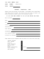
WARRANTY
REGISTRATION
Please fill out this form and return it to Horner Electric.
FORM
This information is vital to Horner Electric,
should warranty service be required. This document is also used to keep you informed of new
product enhancements, software revisions and documentation updates.
IT
IS
IN
YOUR
BEST
INTEREST
TO
FILL
OUT
AND
RETURN
THIS
FORM!
Date of purchase:
Name:
Title:
Company:
Department/Division:
Street Address:
City/State/Zip:
Area Code/Phone Number:
Purchased from (Distributor):
Please indicate the type of application where this product is to be used, check all that apply:
Chemical processing
Demo equipment
Education
Energy management
Food processing
Military
Product assembly/testing
Waste processing
Other (specify)
product:
F O L D
STAMP
Horner APG
APG - Controls Division
640 N. Sherman Drive Street
Indianapolis, Indiana
46201-3899
ATTN:
Warranty Registration Department
F O L D
PREFACE
Page iv
PREFACE
This manual explains how to use the Horner APG Operator Interface Unit
for use with the GE
Fanuc Genius I/O Network and Universal Automation's FloPro.
Copyright (C) 1992 Horner APG, LLC., 640 N. Sherman Drive, Indianapolis Indiana 462013899.
All rights reserved.
No part of this publication may be reproduced, transmitted,
transcribed, stored in a retrieval system, or translated into any language or computer language,
in any form by any means, electronic, mechanical, magnetic, optical, chemical, manual or
otherwise, without the prior agreement and written permission of Horner Electric, Inc.
Information in this document is subject to change without notice and does not represent a
commitment on the part of Horner APG, LLC.
Genius, Logicmaster and Series 90 are trademarks of GE Fanuc Automation North America
Inc.
FloPro is a trademark of Universal Automation.
Page v
PREFACE
LIMITED
WARRANTY
AND
LIMITATION
OF
LIABILITY
Horner APG, LLC. Inc. ("HE") warrants to the original purchaser that the Operator Interface Unit
manufactured by HE is free from defects in material and workmanship under normal use and
service. The obligation of HE under this warranty shall be limited to the repair or exchange of any
part or parts which may prove defective under normal use and service within two years from the
date of manufacture or eighteen (18) months from the date of installation by the original
purchaser whichever occurs first, such defect to be disclosed to the satisfaction of HE after
examination by HE of the allegedly defective part or parts. THIS WARRANTY IS EXPRESSLY
IN LIEU OF ALL OTHER WARRANTIES EXPRESSED OR IMPLIED INCLUDING THE
WARRANTIES OF MERCHANTABILITY AND FITNESS FOR USE AND OF ALL OTHER
OBLIGATIONS OR LIABILITIES AND HE NEITHER ASSUMES, NOR AUTHORIZES ANY
OTHER PERSON TO ASSUME FOR HE, ANY OTHER LIABILITY IN CONNECTION WITH
THE SALE OF THIS OPERATOR INTERFACE UNIT. THIS WARRANTY SHALL NOT APPLY
TO THIS OPERATOR INTERFACE UNIT OR ANY PART THEREOF WHICH HAS BEEN
SUBJECT TO ACCIDENT, NEGLIGENCE, ALTERATION, ABUSE, OR MISUSE. HE MAKES
NO WARRANTY WHATSOEVER IN RESPECT TO ACCESSORIES OR PARTS NOT SUPPLIED BY HE.
THE TERM "ORIGINAL PURCHASER", AS USED IN THIS WARRANTY,
SHALL BE DEEMED TO MEAN THAT PERSON FOR WHOM THE OPERATOR INTERFACE
UNIT IS ORIGINALLY INSTALLED.
THIS WARRANTY SHALL APPLY ONLY WITHIN THE
BOUNDARIES OF THE CONTINENTAL UNITED STATES.
In no event, whether as a result of breach of contract, warranty, tort (including negligence) or
otherwise, shall HE or its suppliers be liable of any special, consequential, incidental or penal
damages including, but not limited to, loss of profit or revenues, loss of use of the products or
any associated equipment, damage to associated equipment, cost of capital, cost of substitute
products, facilities, services or replacement power, down time costs, or claims of original
purchaser's customers for such damages.
To obtain warranty service, return the product to your distributor after obtaining a "Return
Material Authorization".
Include a description of the problem, proof of purchase, post paid,
insured and in a suitable package.
PREFACE
Page vi
ABOUT
THE
PROGRAM
EXAMPLES
The example programs and program segments in this manual are included solely for illustrative
purposes.
Due to the many variables and requirements associated with any particular
installation, Horner Electric cannot assume responsibility or liablity for actual use based on the
examples and diagrams. It is the sole responsibility of the system designer utilizing this software
to appropriately design the end system, to appropriately integrate the Operator Interface Unit
and to make safety provisions for the end equipment as is usual and customary in industrial
applications as defined in any codes or standards which apply.
Page vii
PREFACE
TABLE
CHAPTER
1.1
1.2
1.3
1.4
CHAPTER
OF
1:
CONTENTS
.
.
.
.
.
What You Have
.
.
.
Operator Interface Unit Features .
Hardware Description
.
.
Specifications
.
.
.
.
.
.
.
.
.
.
.
.
.
.
.
Page
Page
Page
Page
.
.
.
.
.
.
.
.
Page 2-1
Page 2-1
.
.
.
.
.
.
.
.
.
.
.
.
.
.
.
Page 2-2
.
Page
.
Page
.
Page
.
Page
2:
INTRODUCTION
.
Page 1-1
1-1
1-1
1-2
1-2
INSTALLATION
2.1
2.2
Mounting Requirements
Power Requirements
2.3
2.4
2.5
2.6
2.7
Genius Network Connector.
RS232 Connector .
.
GENI Configuration .
.
OIU DIP Switches .
.
Logicmaster 90-70 Configuration
APPENDIX
A:
PANEL
APPENDIX
B:
RS-232
APPENDIX
C:
DISPLAYABLE
APPENDIX
D:
TECHNICAL
.
.
CUTOUT
CABLE
PINOUT
CHARACTERS
INFORMATION
2-2
2-3
2-5
2-6
CHAPTER
1:
INTRODUCTION
CHAPTER
1:
Page 1-1
INTRODUCTION
Congratulations on your purchase of the Operator Interface Unit. This unit has been designed using state-of-the-art electronic components and incorporates a sophisticated firmware package that gives the Original Equipment Manufacturer (OEM) the ability to utilize this
unit with the powerful FloPro Development Package from Universal Automation.
1.1
What
You
Have
The Operator Interface Unit (OIU) comes complete with the following items:
1.2
A.
Assembled OIU module and mounting hardware, including the
Genius T M Network Interface board (GENI).
B.
Aluminum Rear Cover for OIU (Available January, 1993).
C.
This manual.
Operator
Interface
Unit
Features
The Horner Operator Interface Unit provides the following features:
A.
Gasketed NEMA 4-12 panel with a rugged Lexan T M overlay, mounting hard
ware included.
B.
Four line by 20 character dot-matrix vacuum-fluorescent display.
C.
Tactile feel keypad with numeric support plus special function keys.
D.
Integrated Genius Network Interface board (GENI) for communications on
GE Fanuc's Genius Distributed I/O Network.
E.
Acts as a high-performance FloPro Remote Message Unit by communicating
.
.
over a high speed I/O network instead of a slower, serial based connection.
F.
Standard 9-pin RS232 communications port, for connection to a GE Fanuc
PowerMate Motion Controller.
G.
Optional Auxiliary RS232 communications port for communications with a
second GE Fanuc PowerMate Motion Controller.
Page 1-2
1.3
CHAPTER
Hardware
1:
INTRODUCTION
Description
The Operator Interface Unit (HE693OIU910) consists of six main components, and one
optional component. They are:
A)
Keypad / Mounting plate.
B)
Main Circuit Board.
C)
Vacuum Fluorescent Display Circuit Board.
D)
Power Supply Circuit Board.
E)
Genius Network Interface (GENI) Board.
F)
Aluminum Rear Cover.
G)
(Optional)
Auxiliary RS232 Circuit Board. (HE-BUS architecture).
The OIU is a microprocessor-based high-performance communications device. The core of
the Main Circuit Board is the Intel 80C152 microprocessor running at 11.0592 MegaHertz.
The “firmware” memory is contained in a 27C256 EPROM device. The Main Circuit Board is
also equipped with 32K bytes of high-speed static RAM memory. There is no retained
memory on the unit. The OIU incorporates a Genius Network Interface board (GENI) that
provides the link to the Genius network. The initial OIU power supply accepts a wide AC
input range. A standard 24VDC power supply will be standard after January 1, 1993.
1.4
Specifications
Mounting
Requirements:
Panel Mounting, NEMA 4-12
Communications:
Genius Network Interface (GENI)
Additional
Standard RS232 for PowerMate.
Optional Auxiliary RS232 for PowerMate
Power
Communications:
Requirements:
DC Version
Operating
Non-Volatile
Environment:
Memory:
12.5-32 VDC, 14 Watts power max.
0 to 60° C. (32 to 140° F).
0 to 95% humidity (non-condesing).
None
CHAPTER
2:INSTALLATION
CHAPTER 2:
2.1
Mounting
Page 2-1
INSTALLATION
Requirements
The OIU is designed for permanent panel mounting.
To install the OIU:
A.
Cut the host panel as described by the drawing in Appendix
A.
B.
Make sure all terminal connectors are removed from the OIU.
C.
Remove the aluminum back cover (if installed), by removing the screws
securing it to the OIU. Carefully lift the cover off the rear of the OIU a few
inches, disconnecting the power terminal from the power supply circuit board.
The rear cover should now be completely free of the OIU.
D.
Remove the six #6-32 hex nuts and washers from the outer mounting studs
on the rear of the OIU panel.
E.
Insert the OIU module through the front panel cutout.
should lie between the host panel and the OIU panel.
The gasket material
F.
Install the six #6-32 nuts and lock-washers on the six mounting studs of the
OIU. Tighten these nuts until the gasket material forms a tight seal, do not
overtighten.
G.
Re-install the rear cover (if present).
Be sure to re-connect the power
terminal to the power supply circuit board. Re-connect all terminal
connectors (power and Genius network terminals). This completes the mechanical installation of the OIU module.
2.2
Power Requirements
The OIU power supply requires a DC supply voltage between 12 and 32 volts. A maximum
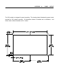
of 14 watts will be drawn by the OIU. The OIU power supply features a 3-position,
removeable terminal block. See Figure 2-1 for connector location. The pinout for this
connector is shown below in Table 2-1.
Table 2-1.
DC connector pinout
Pin
Signal
1
Frame Ground
2
DC Common
3
+12-32VDC
Page 2-2
CHAPTER
2:
INSTALLATION
RS-232
Connector
DB-9S
Optional
RS-232
Connector
DB-9S
Genius Bus
Connector
Power
Connector
(on lower
board)
Figure 2-1.
2.3
Genius
Network
Connectors
Connector
The OIU is also equipped with a 4-pin Genius bus connector. The mating connector provides screw terminals for each circuit. The pinout for this connector is as follows:
Pin
Table 2-2.
2.4
RS232
Signal
1
Serial 1
2
Serial 2
3
Shield Out
4Genius Network
Shield
In
Connector
Pinout
Connector(s)
The 9-pin “D” connectors on the main circuit board and optional auxiliary port provide RS232
interfaces to two GE Fanuc PowerMate Motion Controllers. The OIU-to-PowerMate cable
pinout is shown in Appendix B. For more technical information on the communications
between the OIU and the PowerMate, see Appendix D.
CHAPTER
2:INSTALLATION
2.5
Configuration
GENI
Page 2-3
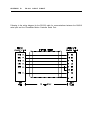
The GENI board (located on the rear of the OIU module) is equipped with a bank of 8 “DIP”
switches. DO NOT CONFUSE THIS DIP SWITCH WITH THE 6-POSITION DIP SWITCH
ON THE MAIN CIRCUIT BOARD DESCRIBED LATER. These switches are used to configure the Genuis “bus” address or “Device Number” for the OIU module, and to set the
module’s Genius baud rate.
Each device on the Genius network must have a unique “Device Number” (0 to 31). The OIU
may be configured for any device number, however the following conventions should be
followed when chosing the device number for the OIU:
A.
B.
C.
The bus controller is usually configured as device number 31.
The redundant bus controller (if any) is usually configured as device number
30.
The Hand-Held monitor is usually configured as device number 0.
When shipped from the factory, the OIU dip switches are configured for device number 29,
and for communication baud rate of 153.6K standard. Multiple OIUs may reside on the
network, provided that they have unique device numbers. Available dip switch settings are
illustrated in Figure 2-2.
Page 2-4
8
CHAPTER
7
2:
INSTALLATION
6
5
4
3
2
1
5
4
3
2
1
addres
5
4
3
2
1
addres
CLOSD
CLOSD
CLOSD
CLOSD
CLOSD
0
OPEN
CLOSD
CLOSD
CLOSD
CLOSD
16
CLOSD
CLOSD
CLOSD
CLOSD
OPEN
1
OPEN
CLOSD
CLOSD
CLOSD
OPEN
17
CLOSD
CLOSD
CLOSD
OPEN
CLOSD
2
OPEN
CLOSD
CLOSD
OPEN
CLOSD
18
CLOSD
CLOSD
CLOSD
OPEN
OPEN
3
OPEN
CLOSD
CLOSD
OPEN
OPEN
19
CLOSD
CLOSD
OPEN
CLOSD
CLOSD
4
OPEN
CLOSD
OPEN
CLOSD
CLOSD
20
CLOSD
CLOSD
OPEN
CLOSD
OPEN
5
OPEN
CLOSD
OPEN
CLOSD
OPEN
21
CLOSD
CLOSD
OPEN
OPEN
CLOSD
6
OPEN
CLOSD
OPEN
OPEN
CLOSD
22
CLOSD
CLOSD
OPEN
OPEN
OPEN
7
OPEN
CLOSD
OPEN
OPEN
OPEN
23
CLOSD
OPEN
CLOSD
CLOSD
CLOSD
8
OPEN
OPEN
CLOSD
CLOSD
CLOSD
24
CLOSD
OPEN
CLOSD
CLOSD
OPEN
9
OPEN
OPEN
CLOSD
CLOSD
OPEN
25
CLOSD
OPEN
CLOSD
OPEN
CLOSD
10
OPEN
OPEN
CLOSD
OPEN
CLOSD
26
CLOSD
OPEN
CLOSD
OPEN
OPEN
11
OPEN
OPEN
CLOSD
OPEN
OPEN
27
CLOSD
OPEN
OPEN
CLOSD
CLOSD
12
OPEN
OPEN
OPEN
CLOSD
CLOSD
28
CLOSD
OPEN
OPEN
CLOSD
OPEN
13
OPEN
OPEN
OPEN
CLOSD
OPEN
29
CLOSD
OPEN
OPEN
OPEN
CLOSD
14
OPEN
OPEN
OPEN
OPEN
CLOSD
30
CLOSD
OPEN
OPEN
OPEN
OPEN
15
OPEN
OPEN
OPEN
OPEN
OPEN
31
7
6
CLOSD
CLOSD
CLOSD
OPEN
38.4K
OPEN
CLOSD
76.8K
OPEN
OPEN
ALWAYS
Figure 2-2 .
baud
153.6K
153.6K
rate
extended
standard
OPEN
GENI DIP Switch Assignments
CHAPTER
2:
INSTALLATION
Page 2-5
2.6
OIU DIP Switches
The MAIN circuit board is equipped with a bank of 6 “DIP” switches. These switches are
accessable by removal of the metal back cover. The user should never need to change
the default position(s). The default positions are indicated in BOLD below. These
switches are used to configure the following OIU options:
6
5
4
3
2
1
Always
CLOSED
Always
CLOSED
Always
CLOSED
Firmware Size (CLOSED=64K,
Watchdog
RS-232
Figure 2-3 .
2.7
Logicmaster
90-70
Enable
Mode
OPEN=32K)
(CLOSED=enable,
(CLOSED=normal,
OPEN=disable)
OPEN=test)
MAIN board DIP Switch Assignments
Configuration
The 90-70 Genius Bus Controller must be configured by Logicmaster to communicate with
the OIU. The proper settings are as follows:
GENI-based device
Config Mode:
manual
To:
(bit type memory)*
Input Length:
8
2.8
FloPro
*the proper bit memory type
(%I, %M, %G, etc.) will be
determined by GE Fanuc and
Universal Automation
Configuration
Consult documentation provided with Universal Automation FloPro for the configuration of
Remote Message Units (OIUs) in FloPro. Future editions of this manual may provide this
information for convenience.
APPENDIX
A:
PANEL
CUTOUT
The OIU module is designed for panel mounting. The drawing below illustrates the panel cutout
required for OIU module mounting. All dimensions shown in brackets are in millimeters, and
those shown without brackets are in inches.
APPENDIX
B:
RS-232
CABLE
PINOUT
Following is the wiring diagram for the RS-232 cable for communications between the OIU910
serial port and the PowerMate Motion Controller Serial Port..
APPENDIX
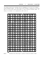
The following chart lists the characters which
vacuum fluorescent display. The ASCII code
digit 0-F in hex) and the column (second digit
instance, the character "q" is represented by
2nd
1st
DISPLAYABLE
CHARACTERS
are displayable by the 4-line by 20 character
for each character is indicated by the row (first
0-F in hex) in which the character resides. For
ASCII code 17H.
0 1 2 3 4 5 6 7 8 9 A B C D E F
p Ç É á
α § À
≤
1 A Q a
q
ü æ
í
β
È
≥
"
2 B R b
r
é Æ ó
γ
Ù
≠
Ë
⊥
0
DP
1
DC
!
2
DC
0 @ P
`
3
DE
#
3 C S c
s
â
ô
ú
∆
4
DI
$
4 D T
d
t
ä
ö
ñ
ε
5
% 5 E U e
u
à
ò Ñ η
6
& 6 F V
v
å
û
θ
7
'
7 G W g w
ç
ù
λ
ÿ
¿ µ
f
∫
∞
Â
≈
²
Ê
≡
³
Î
⊕
Ô
θ
8
BS
(
8 H X h
x
ê
9
HT
)
9
I
Y
i
y
ë Ö
Π √ Û
←
A
LF
*
:
J
Z
j
z
è Ü ¬
ρ
→
B
+
;
K
[
k
{
ï
¢ ½ σ
C
,
< L
\
l
|
î
£ ¼ τ
-
= M
] m
}
ì
¥
.
> N
^
n
~ Ä
/
? O _
o
D
CR
E
F
Note:
C:
RS
Å ƒ
±
Γ
φ
UF
« Ω
UF
Σ
UF
¡
»
°
Characters with second digit "E" (column E above) are Russian Letters
APPENDIX
D:
TECHNICAL
INFORMATION
APPENDIX
D:
TECHNICAL
INFORMATION
APPENDIX
D:
TECHNICAL
INFORMATION
APPENDIX
D:
TECHNICAL
INFORMATION
APPENDIX
D:
TECHNICAL
INFORMATION
APPENDIX
D:
TECHNICAL
INFORMATION
APPENDIX
D:
TECHNICAL
INFORMATION
APPENDIX
D:
TECHNICAL
INFORMATION
APPENDIX
D:
TECHNICAL
INFORMATION
APPENDIX
D:
TECHNICAL
INFORMATION
APPENDIX
D:
TECHNICAL
INFORMATION
APPENDIX
D:
TECHNICAL
INFORMATION
APPENDIX
D:
TECHNICAL
INFORMATION
APPENDIX
D:
TECHNICAL
INFORMATION
APPENDIX
D:
TECHNICAL
INFORMATION
APPENDIX
D:
TECHNICAL
INFORMATION
APPENDIX
D:
TECHNICAL
INFORMATION