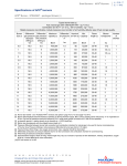
1
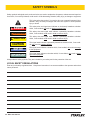
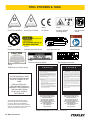
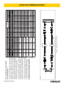
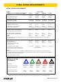
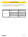
WS10
HYDRAULIC
WELD SHEAR
USER MANUAL
Safety, Operation and Maintenance
© 2014 Stanley Black & Decker, Inc.
New Britain, CT 06053
U.S.A.
28860 2/2015 Ver. 13
DECLARATION OF CONFORMITY
DECLARATION OF CONFORMITY
ÜBEREINSTIMMUNGS-ERKLARUNG
DECLARATION DE CONFORMITE CEE
DECLARACION DE CONFORMIDAD
DICHIARAZIONE DI CONFORMITA
Hydraulic Tools
______________________________________________________________________
I, the undersigned:
Ich, der Unterzeichnende:
Je soussigné:
El abajo firmante:
lo sottoscritto:
Weisbeck, Andy
Surname and First names/Familiennname und Vornamen/Nom et prénom/Nombre y apellido/Cognome e nome
hereby declare that the equipment specified hereunder:
bestätige hiermit, daß erklaren Produkt genannten Werk oder Gerät:
déclare que l’équipement visé ci-dessous:
Por la presente declaro que el equipo se especifica a continuación:
Dichiaro che le apparecchiature specificate di seguito:
1.
Category:
Kategorie:
Catégorie:
Categoria:
Categoria:
Weld Shear, Hydraulic
2.
Make/Marke/Marque/Marca/Marca
Stanley
3.
Type/Typ/Type/Tipo/Tipo:
WS1032101A, WS1022001A
4.
Serial number of equipment:
Seriennummer des Geräts:
Numéro de série de l’équipement:
Numero de serie del equipo:
Matricola dell´attrezzatura:
All
Has been manufactured in conformity with
Wurde hergestellt in Übereinstimmung mit
Est fabriqué conformément
Ha sido fabricado de acuerdo con
E’ stata costruita in conformitá con
Directive/Standards
Richtlinie/Standards
Directives/Normes
Directriz/Los Normas
Direttiva/Norme
No.
Nr
Numéro
No
n.
Approved body
Prüfung durch
Organisme agréé
Aprobado
Collaudato
Machinery Directive
EN ISO
2006/42/EC:2006
12100:2010
Self
Self
5.
Special Provisions:
None
Spezielle Bestimmungen:
Dispositions particulières:
Provisiones especiales:
Disposizioni speciali:
6.
Representative in the Union: Patrick Vervier, Stanley Dubuis 17-19, rue Jules Berthonneau-BP 3406 41034 Blois Cedex, France.
Vertreter in der Union/Représentant dans l’union/Representante en la Union/Rappresentante presso l’Unione
Done at/Ort/Fait à/Dado en/Fatto a Stanley Hydraulic Tools, Milwaukie, Oregon USA
Signature/Unterschrift/Signature/Firma/Firma
Position/Position/Fonction/Cargo/Posizione
2 ► WS10 User Manual
Director of Product Development
Date/Datum/le/Fecha/Data
1-10-11
TABLE OF CONTENTS
DECLARATION OF CONFORMITY...........................................................................................................................2
SAFETY SYMBOLS...................................................................................................................................................4
SAFETY PRECAUTIONS...........................................................................................................................................5
TOOL STICKERS & TAGS.........................................................................................................................................6
TOOL HOSE INFORMATION.....................................................................................................................................7
HOSE RECOMMENDATIONS ..................................................................................................................................8
HTMA REQUIREMENTS ...........................................................................................................................................9
OPERATION ............................................................................................................................................................10
EQUIPMENT PROTECTION & CARE ....................................................................................................................12
TROUBLESHOOTING.............................................................................................................................................13
SPECIFICATIONS....................................................................................................................................................14
ACCESSORIES.......................................................................................................................................................14
PARTS ILLUSTRATION WS10321..........................................................................................................................15
PARTS LIST WS10321............................................................................................................................................16
PARTS ILLUSTRATION WS10220..........................................................................................................................17
PARTS LIST WS10220............................................................................................................................................18
IMPORTANT
To fill out a Product Warranty Validation form, and for information on your warranty,
visit Stanleyhydraulics.com and select the Company tab, Warranty.
(NOTE: The warranty Validation record must be submitted to validate the warranty).
SERVICING: This manual contains safety, operation, and routine maintenance instructions. Stanley Hydraulic Tools
recommends that servicing of hydraulic tools, other than routine maintenance, must be performed by an authorized
and certified dealer. Please read the following warning.
WARNING
SERIOUS INJURY OR DEATH COULD RESULT FROM THE IMPROPER REPAIR OR SERVICE OF THIS
TOOL.
REPAIRS AND / OR SERVICE TO THIS TOOL MUST ONLY BE DONE BY AN AUTHORIZED AND
CERTIFIED DEALER.
For the nearest authorized and certified dealer, call Stanley Hydraulic Tools at the number listed on the back of this
manual and ask for a Customer Service Representative.
WS10 User Manual ◄ 3
SAFETY SYMBOLS
Safety symbols and signal words, as shown below, are used to emphasize all operator, maintenance and repair actions which, if not strictly followed, could result in a life-threatening situation, bodily injury or damage to equipment.
This is the safety alert symbol. It is used to alert you to potential personal injury
hazards. Obey all safety messages that follow this symbol to avoid possible
injury or death.
DANGER
This safety alert and signal word indicate an imminently hazardous situation
which, if not avoided, will result in death or serious injury.
WARNING
This safety alert and signal word indicate a potentially hazardous situation
which, if not avoided, could result in death or serious injury.
CAUTION
This safety alert and signal word indicate a potentially hazardous situation
which, if not avoided, could result in death or serious injury.
CAUTION
This signal word indicates a potentially hazardous situation which, if not avoided, may result in property damage.
NOTICE
This signal word indicates a situation which, if not avoided, will result in damage
to the equipment.
IMPORTANT
This signal word indicates a situation which, if not avoided, may result in damage to the equipment.
Always observe safety symbols. They are included for your safety and for the protection of the tool.
LOCAL SAFETY REGULATIONS
Enter any local safety regulations here. Keep these instructions in an area accessible to the operator and maintenance personnel.
4 ► WS10 User Manual
SAFETY PRECAUTIONS
Tool operators and maintenance personnel must always
comply with the safety precautions given in this manual
and on the stickers and tags attached to the tool and
hose.
These safety precautions are given for your safety. Review them carefully before operating the tool and before
performing general maintenance or repairs.
Supervising personnel should develop additional precautions relating to the specific work area and local
safety regulations. If so, place the added precautions in
the space provided in this manual.
The model WS10 Hydraulic Weld Shear will provide
safe and dependable service if operated in accordance
with the instructions given in this manual. Read and understand this manual and any stickers and tags attached
to the pressure washer and hose before operation. Failure to do so could result in personal injury or equipment
damage.
The operator must start in a work area without bystanders. Flying debris can cause serious injury.
• Do not operate the tool unless thoroughly trained or
under the supervision of an instructor. Establish a training program for all operators to ensure safe operation.
• Always wear safety equipment such as goggles, ear
and head protection, and safety shoes at all times when
operating the tool.
• The operator must be familiar with all prohibited work
areas such as excessive slopes and dangerous terrain
conditions.
• Always connect hoses to the tool hose couplers before
energizing the hydraulic power source. Be sure all hose
connections are tight and are in good condition.
• Do not operate the tool at oil temperatures above
140°F/60°C. Operation at higher temperatures can
cause higher than normal temperatures at the tool which
can result in operator discomfort.
• Never wear loose clothing that can get entangled in the
working parts of the tool.
• To avoid personal injury or equipment damage, all tool
repair, maintenance and service must only be performed
by authorized and properly trained personnel.
• The hydraulic circuit control valve must be in the OFF
position when coupling or uncoupling the tool. Wipe all
couplers clean before connecting. Failure to do so may
result in damage to the quick couplers and cause overheating. Use only lint-free cloths.
• Never transport or carry the tool with the unit energized.
• Keep all parts of your body away from the cylinders
and shear blades. Long hair or loose clothing can become drawn into moving components.
• Do not use a shear blade that is cracked, chipped or
otherwise damaged. Always inspect shear blades for
possible damage before installation or use.
• Do not operate a damaged, improperly adjusted or incompletely assembled tool.
• Do not exceed the rated limits of the tool or use the tool
for applications beyond its design capacity.
• Always keep critical tool markings, such as labels and
warning stickers legible.
• Eye injury and cutting or severing of body parts is possible if proper procedures are not followed.
• Do not inspect, clean or replace the sher baldes while
the hydraulic power source is connected. Do not inspect
or clean the tool while the hydraulic power source is connected. Accidental engagement of the tool can cause
serious injury.
WS10 User Manual ◄ 5
TOOL STICKERS & TAGS
11207
11206
28322
31064
31049
Circuit Type D Sticker
Circuit Type C Sticker
CE Sticker
Crushing Hazard
Warning Sticker
Eye Protection
Sticker
35294
25610
372037
28788
No Hammer Sticker
Railroad Help Desk Sticker
Serial Number Plate
Manual Sticker
29188
17572
35295
Pinch Point Warning Sticker
Roller Adjustment Sticker
GPM/Pressure Caution Sticker
D A N G E R
1.
NOTE:
THE INFORMATION LISTED
ON THE STICKERS SHOWN,
MUST BE LEGIBLE AT ALL
TIMES.
REPLACE DECALS IF
THEY BECOME WORN OR
DAMAGED. REPLACEMENTS
ARE AVAILABLE FROM
YOUR LOCAL STANLEY
DISTRIBUTOR.
The safety tag (P/N 15875) at right is
attached to the tool when shipped from
the factory. Read and understand the
safety instructions listed on this tag before
removal. We suggest you retain this tag and
attach it to the tool when not in use.
FAILURE TO USE HYDRAULIC HOSE LABELED AND CERTIFIED AS NON-CONDUCTIVE WHEN USING HYDRAULIC
TOOLS ON OR NEAR ELECTRICAL LINES MAY RESULT IN
DEATH OR SERIOUS INJURY.
BEFORE USING HOSE LABELED AND CERTIFIED AS NONCONDUCTIVE ON OR NEAR ELECTRIC LINES BE SURE THE
HOSE IS MAINTAINED AS NON-CONDUCTIVE. THE HOSE
SHOULD BE REGULARLY TESTED FOR ELECTRIC CURRENT LEAKAGE IN ACCORDANCE WITH YOUR SAFETY
DEPARTMENT INSTRUCTIONS.
2.
A HYDRAULIC LEAK OR BURST MAY CAUSE OIL INJECTION INTO THE BODY OR CAUSE OTHER SEVERE
PERSONAL INJURY.
A.
DO NOT EXCEED SPECIFIED FLOW AND PRESSURE
FOR THIS TOOL. EXCESS FLOW OR PRESSURE MAY
CAUSE A LEAK OR BURST.
B.
DO NOT EXCEED RATED WORKING PRESSURE OF
HYDRAULIC HOSE USED WITH THIS TOOL. EXCESS
PRESSURE MAY CAUSE A LEAK OR BURST.
C. CHECK TOOL HOSE COUPLERS AND CONNECTORS
DAILY FOR LEAKS. DO NOT FEEL FOR LEAKS WITH
YOUR HANDS. CONTACT WITH A LEAK MAY RESULT
IN SEVERE PERSONAL INJURY.
D A N G E R
D. DO NOT LIFT OR CARRY TOOL BY THE HOSES. DO
NOT ABUSE HOSE. DO NOT USE KINKED, TORN OR
DAMAGED HOSE.
3.
MAKE SURE HYDRAULIC HOSES ARE PROPERLY CONNECTED TO THE TOOL BEFORE PRESSURING SYSTEM.
SYSTEM PRESSURE HOSE MUST ALWAYS BE CONNECTED TO TOOL “IN” PORT. SYSTEM RETURN HOSE
MUST ALWAYS BE CONNECTED TO TOOL “OUT” PORT.
REVERSING CONNECTIONS MAY CAUSE REVERSE
TOOL OPERATION WHICH CAN RESULT IN SEVERE
PERSONAL INJURY.
4.
DO NOT CONNECT OPEN-CENTER TOOLS TO CLOSEDCENTER HYDRAULIC SYSTEMS. THIS MAY RESULT IN
LOSS OF OTHER HYDRAULIC FUNCTIONS POWERED BY
THE SAME SYSTEM AND/OR SEVERE PERSONAL INJURY.
5.
BYSTANDERS MAY BE INJURED IN YOUR WORK AREA.
KEEP BYSTANDERS CLEAR OF YOUR WORK AREA.
6.
WEAR HEARING, EYE, FOOT, HAND AND HEAD PROTECTION.
7.
TO AVOID PERSONAL INJURY OR EQUIPMENT DAMAGE,
ALL TOOL REPAIR MAINTENANCE AND SERVICE MUST
ONLY BE PERFORMED BY AUTHORIZED AND PROPERLY
TRAINED PERSONNEL.
I M P O R T A N T
I M P O R T A N T
READ OPERATION MANUAL AND
SAFETY INSTRUCTIONS FOR THIS
TOOL BEFORE USING IT.
READ OPERATION MANUAL AND
SAFETY INSTRUCTIONS FOR THIS
TOOL BEFORE USING IT.
USE ONLY PARTS AND REPAIR
PROCEDURES APPROVED BY
STANLEY AND DESCRIBED IN THE
OPERATION MANUAL.
USE ONLY PARTS AND REPAIR
PROCEDURES APPROVED BY
STANLEY AND DESCRIBED IN THE
OPERATION MANUAL.
TAG TO BE REMOVED ONLY BY
TOOL OPERATOR.
TAG TO BE REMOVED ONLY BY
TOOL OPERATOR.
SEE OTHER SIDE
SEE OTHER SIDE
SAFETY TAG P/N 15875 (Shown smaller then actual size)
6 ► WS10 User Manual
TOOL HOSE INFORMATION
The rated working pressure of the hydraulic hose must be equal to or higher than the relief valve setting on the hydraulic system. There are three types of hydraulic hose that meet this requirement and are authorized for use with
Stanley Hydraulic Tools. They are:
Certified non-conductive — constructed of thermoplastic or synthetic rubber inner tube, synthetic fiber braid
reinforcement, and weather resistant thermoplastic or synthetic rubber cover. Hose labeled certified nonconductive is the only hose authorized for use near electrical conductors.
Wire-braided (conductive) — constructed of synthetic rubber inner tube, single or double wire braid reinforcement, and weather resistant synthetic rubber cover. This hose is conductive and must never be used near
electrical conductors.
Fabric-braided (not certified or labeled non-conductive) — constructed of thermoplastic or synthetic rubber inner tube, synthetic fiber braid reinforcement, and weather resistant thermoplastic or synthetic rubber cover. This
hose is not certified non-conductive and must never be used near electrical conductors.
HOSE SAFETY TAGS
To help ensure your safety, the following DANGER tags are attached to all hose purchased from Stanley Hydraulic
Tools. DO NOT REMOVE THESE TAGS.
If the information on a tag is illegible because of wear or damage, replace the tag immediately. A new tag may be
obtained from your Stanley Distributor.
D A N G E R
D A N G E R
1.
FAILURE TO USE HYDRAULIC HOSE LABELED AND CERTIFIED AS NON-CONDUCTIVE
WHEN USING HYDRAULIC TOOLS ON OR NEAR ELECTRIC LINES MAY RESULT IN
DEATH OR SERIOUS INJURY.
FOR PROPER AND SAFE OPERATION MAKE SURE THAT YOU HAVE BEEN PROPERLY TRAINED IN CORRECT PROCEDURES REQUIRED FOR WORK ON OR AROUND
ELECTRIC LINES.
2.
BEFORE USING HYDRAULIC HOSE LABELED AND CERTIFIED AS NON-CONDUCTIVE
ON OR NEAR ELECTRIC LINES. WIPE THE ENTIRE LENGTH OF THE HOSE AND FITTING WITH A CLEAN DRY ABSORBENT CLOTH TO REMOVE DIRT AND MOISTURE AND
TEST HOSE FOR MAXIMUM ALLOWABLE CURRENT LEAKAGE IN ACCORDANCE WITH
SAFETY DEPARTMENT INSTRUCTIONS.
3.
DO NOT EXCEED HOSE WORKING PRESSURE OR ABUSE HOSE. IMPROPER USE
OR HANDLING OF HOSE COULD RESULT IN BURST OR OTHER HOSE FAILURE.
KEEP HOSE AS FAR AWAY AS POSSIBLE FROM BODY AND DO NOT PERMIT DIRECT
CONTACT DURING USE. CONTACT AT THE BURST CAN CAUSE BODILY INJECTION
AND SEVERE PERSONAL INJURY.
4.
HANDLE AND ROUTE HOSE CAREFULLY TO AVOID KINKING, ABRASION, CUTTING, OR
CONTACT WITH HIGH TEMPERATURE SURFACES. DO NOT USE IF KINKED. DO NOT
USE HOSE TO PULL OR LIFT TOOLS, POWER UNITS, ETC.
5.
CHECK ENTIRE HOSE FOR CUTS CRACKS LEAKS ABRASIONS, BULGES, OR DAMAGE TO COUPLINGS IF ANY OF THESE CONDITIONS EXIST, REPLACE THE HOSE
IMMEDIATELY. NEVER USE TAPE OR ANY DEVICE TO ATTEMPT TO MEND THE HOSE.
6.
AFTER EACH USE STORE IN A CLEAN DRY AREA.
SEE OTHER SIDE
SIDE 1
SEE OTHER SIDE
(Shown smaller than actual size)
DO NOT REMOVE THIS TAG
DO NOT REMOVE THIS TAG
THE TAG SHOWN BELOW IS ATTACHED TO “CERTIFIED NON-CONDUCTIVE” HOSE
SIDE 2
D A N G E R
D A N G E R
1.
DO NOT USE THIS HYDRAULIC HOSE ON OR NEAR ELECTRIC LINES. THIS HOSE IS
NOT LABELED OR CERTIFIED AS NON-CONDUCTIVE. USING THIS HOSE ON OR NEAR
ELECTRICAL LINES MAY RESULT IN DEATH OR SERIOUS INJURY.
5.
CHECK ENTIRE HOSE FOR CUTS CRACKS LEAKS ABRASIONS, BULGES, OR DAMAGE TO
COUPLINGS IF ANY OF THESE CONDITIONS EXIST, REPLACE THE HOSE IMMEDIATELY.
NEVER USE TAPE OR ANY DEVICE TO ATTEMPT TO MEND THE HOSE.
2.
FOR PROPER AND SAFE OPERATION MAKE SURE THAT YOU HAVE BEEN PROPERLY
TRAINED IN CORRECT PROCEDURES REQUIRED FOR WORK ON OR AROUND ELECTRIC LINES.
6.
AFTER EACH USE STORE IN A CLEAN DRY AREA.
3.
DO NOT EXCEED HOSE WORKING PRESSURE OR ABUSE HOSE. IMPROPER USE OR
HANDLING OF HOSE COULD RESULT IN BURST OR OTHER HOSE FAILURE. KEEP HOSE
AS FAR AWAY AS POSSIBLE FROM BODY AND DO NOT PERMIT DIRECT CONTACT
DURING USE. CONTACT AT THE BURST CAN CAUSE BODILY INJECTION AND SEVERE
PERSONAL INJURY.
4.
HANDLE AND ROUTE HOSE CAREFULLY TO AVOID KINKING, CUTTING, OR CONTACT
WITH HIGH TEMPERATURE SURFACES. DO NOT USE IF KINKED. DO NOT USE HOSE TO
PULL OR LIFT TOOLS, POWER UNITS, ETC.
DO NOT REMOVE THIS TAG
DO NOT REMOVE THIS TAG
THE TAG SHOWN BELOW IS ATTACHED TO “CONDUCTIVE” HOSE.
SEE OTHER SIDE
SEE OTHER SIDE
SIDE 1
SIDE 2
(Shown smaller than actual size)
WS10 User Manual ◄ 7
8 ► WS10 User Manual
All hydraulic hose must meet or exceed
specifications as set forth by SAE J517.
All hydraulic hose must have at least a rated
minimum working pressure equal to the maximum hydraulic system relief valve setting.
This chart is intended to be used for hydraulic
tool applications only based on Stanley Hydraulic Tools tool operating requirements and
should not be used for any other applications.
The chart to the right shows recommended
minimum hose diameters for various hose
lengths based on gallons per minute (gpm)/
liters per minute (lpm). These recommendations are intended to keep return line pressure
(back pressure) to a minimum acceptable level to ensure maximum tool performance.
Tool to Hydraulic Circuit Hose
Recommendations
15-34
MM
Inside Diameter
INCH
USE
(Press/Return)
PSI
up to 10
up to 3
3/8
10
Both
2250
49-60
13-16
FLOW >>>
RETURN
<<< FLOW
PRESSURE
26-100
up to 25
100-200
51-100
up to 50
100-300
51-100
up to 50
26-100
up to 25
8-30
up to 8
30-60
15-30
up to 15
30-90
15-30
up to 15
7.5-30
up to 7.5
Figure 1. Typical Hose Connections
49-60
38-49
10-13
13-16
19-40
5-10.5
38-49
19-40
5-10.5
10-13
19-40
5-10.5
38-49
15-23
10-13
15-23
4-6
19
25.4
16
19
19
25.4
5/8
3/4
3/4
1
19
3/4
1
16
3/4
16
19
3/4
5/8
16
5/8
5/8
16
13
13
10
5/8
1/2
1/2
3/8
Return
Pressure
Return
Pressure
Return
Pressure
Return
Pressure
Both
Return
Pressure
Both
Both
Both
Both
2500
2500
2500
2500
2500
2500
2500
2500
2500
2500
2500
2500
2500
2500
2500
175
175
175
175
175
175
175
175
175
175
175
175
175
175
175
155
BAR
Min. Working Pressure
Certified Non-Conductive Hose - Fiber Braid - for Utility Bucket Trucks
METERS
Hose Lengths
FEET
Conductive Hose - Wire Braid or Fiber Braid -DO NOT USE NEAR ELECTRICAL CONDUCTORS
4-6
4-9
LPM
Oil Flow
GPM
HOSE RECOMMENDATIONS
HTMA / EHTMA REQUIREMENTS
HTMA / EHTMA REQUIREMENTS
HTMA
HYDRAULIC SYSTEM REQUIREMENTS
TYPE I
Nominal Operating Pressure
(at the power supply outlet)
4-6 gpm
(15-23 lpm)
1500 psi
(103 bar)
TOOL TYPE
TYPE II
TYPE RR
7-9 gpm
(26-34 lpm)
1500 psi
(103 bar)
9-10.5 gpm
(34-40 lpm)
1500 psi
(103 bar)
System relief valve setting
(at the power supply outlet)
2100-2250 psi
(145-155 bar)
2100-2250 psi
(145-155 bar)
2200-2300 psi
(152-159 bar)
2100-2250 psi
(145-155 bar)
Maximum back pressure
(at tool end of the return hose)
250 psi
(17 bar)
250 psi
(17 bar)
250 psi
(17 bar)
250 psi
(17 bar)
Measured at a max. fluid viscosity of:
(at min. operating temperature)
400 ssu*
400 ssu*
400 ssu*
400 ssu*
(82 centistokes) (82 centistokes) (82 centistokes) (82 centistokes)
Temperature: Sufficient heat rejection
capacity to limit max. fluid temperature to:
(at max. expected ambient temperature)
140° F
(60° C)
Flow Range
140° F
(60° C)
140° F
(60° C)
TYPE III
11-13 gpm
(42-49 lpm)
1500 psi
(103 bar)
140° F
(60° C)
3 hp
5 hp
6 hp
7 hp
Min. cooling capacity at a temperature
(2.24 kW)
(3.73 kW)
(5.22 kW)
(4.47 kW)
difference of between ambient and fluid
40° F
40° F
40° F
40° F
temps
(22° C)
(22° C)
(22° C)
(22° C)
NOTE:
Do not operate the tool at oil temperatures above 140° F (60° C). Operation at higher temperatures can cause operator
discomfort at the tool.
Filter
Min. full-flow filtration
Sized for flow of at least:
(For cold temp. startup and max.
dirt-holding capacity)
25 microns
30 gpm
(114 lpm)
Hydraulic fluid Petroleum based
(premium grade, anti-wear, non-conductive)
Viscosity (at min. and max. operating temps)
100-400 ssu*
25 microns
30 gpm
(114 lpm)
25 microns
30 gpm
(114 lpm)
100-400 ssu*
100-400 ssu*
(20-82 centistokes)
25 microns
30 gpm
(114 lpm)
100-400 ssu*
NOTE:
When choosing hydraulic fluid, the expected oil temperature extremes that will be experienced in service determine the
most suitable temperature viscosity characteristics. Hydraulic fluids with a viscosity index over 140 will meet the requirements
over a wide range of operating temperatures.
*SSU = Saybolt Seconds Universal
EHTMA
HYDRAULIC SYSTEM
REQUIREMENTS
CLASSIFICATION
B
C
D
Nominal Operating Pressure
(at the power supply outlet)
3.5-4.3 gpm
(13.5-16.5 lpm)
1870 psi
(129 bar)
4.7-5.8 gpm
(18-22 lpm)
1500 psi
(103 bar)
7.1-8.7 gpm
(27-33 lpm)
1500 psi
(103 bar)
9.5-11.6 gpm
(36-44 lpm)
1500 psi
(103 bar)
11.8-14.5 gpm
(45-55 lpm)
1500 psi
(103 bar)
System relief valve setting
(at the power supply outlet)
2495 psi
(172 bar)
2000 psi
(138 bar)
2000 psi
(138 bar)
2000 psi
(138 bar)
2000 psi
(138 bar)
Flow Range
NOTE: These are general hydraulic system requirements. See tool specification page for tool specific requirements
WS10 User Manual ◄ 9
OPERATION
PREPARATION FOR INITIAL USE
On hand pump units, replace the plastic shipping plug
on top of the pump assembly with the breather vent. No
other special unpacking or assembly requirements are
required on either unit prior to usage.
Each unit should be inspected to assure the unit was
not damaged in shipping and does not contain packing
debris.
CHECK HYDRAULIC POWER
SOURCE (POWER UNIT MODEL ONLY)
1. Using a calibrated flowmeter and pressure gauge,
check that the hydraulic power source develops
a flow of 4-10 gpm/15-38 lpm Do Not exceed 140
bar/2000 psi.
2. Make certain the hydraulic power source is equipped
with a relief valve set to open at 2200-2300 psi/151158 bar.
3. Make certain that the power source return pressure
does not exceed 250 psi/17 bar.
4. Check that the hydraulic circuit matches the tool for
open-center (OC) operation.
CHECK TOOL
1. Make sure all tool accessories are correctly installed. Failure to install tool accessories properly
can result in damage to the tool or personal injury.
2. There should be no signs of leaks.
3. The tool should be clean, with all fittings and fasteners tight.
CHECK CONTROL MECHANISM
Hand Pump Models
On hand pump models, check that the directional control
valve operates freely from the neutral position to the forward position and then back to the neutral position and
then to the rearward position. In each position work the
lever to assure movement of the cylinders is free of binding and that the hydraulics are performing as intended.
Power Unit Models
On power unit models, check that the directional control
valve operates freely from the neutral position to the forward position and then through the neutral and rearward
positions.
CONNECT HOSES (Power Unit Model Only)
1. Wipe all hose couplers with a clean lint-free cloth
before making connections.
2. Connect the hoses from the hydraulic power source
10 ► WS10 User Manual
to the hose couplers on the weld shear. It is a good
practice to connect the return hose first and disconnect it last to minimize or avoid trapped pressure
within the cylinders.
3. Observe flow indicators stamped on hose couplers
to be sure that oil will flow in the proper direction.
The female coupler is the inlet coupler.
NOTE::The pressure increase in uncoupled
hoses left in the sun may result in making
them difficult to connect. When possible,
connect the free ends of operating hoses
together.
OPERATING PROCEDURES
POWER UNIT AND HAND PUMP MODELS
CHECKING OPERATION AND
PERFORMANCE
1. Observe all safety precautions.
2. Remove any debris and burrs from the rail joint that
will interfere with the weld shear cutters.
3. Place the weld shear on the rail over the location to
be welded.
4. Adjust the height of the four roller pivots. The pivots
must, once pivoted, be placed under the rail head
with a minimum of clearance to avoid any forcing
during the forward movement of the cutters. This
adjustment is done with the 4 hex nuts.
5. On the power unit model, move the hydraulic circuit
control valve to the "ON" position.
6. On the Weld Shear, move the directional control valve lever to the forward position so that the
shear blade advances. (On hand pump versions,
the shear blade will not advance or retract without
pumping the lever) Check that the shear blade advances without binding. With the cylinders fully extended, there should be a gap of 1/32-1/16 inch between the two shear blades. If this gap is not correct,
do not use the weld shear and have it serviced by an
authorized and certified dealer. If the gap is correct,
retract the shear blade to its most rearward position
by moving the control lever to the rearward position.
The shear blades should now be as far apart as the
tool will permit.
7. Remove the weld shear from the rail.
OPERATION
CUTTING PROCEDURE
1. Proceed with the preparations for welding and put
the molds and accessories in their place.
2. Pour the weld.
3. As soon as permitted by the mold manufacturer's
instructions, remove the two side iron sheets of the
mold. The bottom plate does not need to be removed.
4. Remove any excess sand from the railhead to prevent damage to the cutters.
5. Place the weld shear on the rail so that it straddles
the mold.
6. Pivot the four roller pivots under the rail head by
turning the handle assemblies.
7. Start cutting at the correct time based on the mold
manufacturer's instructions by moving the directional control valve lever forward (hand pump models
require pumping of the lever).
8. Cut to the end of the stroke and hold for approximately 1 to 2 seconds.
9. Move the valve handle to the rearward position for
opening the cutters (hand pump models require
pumping of the lever) and retract the shear blade to
its most rearward position.
10. Pivot the four roller pivots away from the rail and
remove the weld shear from the rail as soon as possible.
11. Quickly remove any excess weld material from the
cutters to prevent overheating.
COLD WEATHER OPERATION
If a power unit model weld shear is to be used during
cold weather, preheat the system hydraulic fluid at low
engine speed.
Power unit models should use normally recommended
fluids with fluid temperature at or above 50° F/10° C
(400 ssu/82 centistokes) before use.
Hand pump models may be warmed by placing them in
a heated compartment.
WS10 User Manual ◄ 11
EQUIPMENT PROTECTION & CARE
NOTICE
In addition to the Safety Precautions found in
this manual, observe the following for equipment
protection and care.
•
Make sure all couplers are wiped clean before connection.
•
The hydraulic circuit control valve must be in the
“OFF” position when coupling or uncoupling hydraulic tools. Failure to do so may result in damage to
the quick couples and cause overheating of the hydraulic system.
•
Do not exceed the rated flow (see Specifications) in this
manual for correct flow rate and model number. Rapid
failure of the internal seals may result.
•
Always keep critical tool markings, such as warning
stickers and tags legible.
•
Tool repair should be performed by experienced personnel only.
•
Always store the tool in a clean dry space, safe from
damage or pilferage.
•
•
Make sure the circuit PRESSURE hose (with male
quick disconnect) is connected to the “IN” port. The
circuit RETURN hose (with female quick disconnect)
is connected to the opposite port. Do not reverse circuit flow. This can cause damage to internal seals.
Make certain that the recommended relief valves are installed in the pressure side of the system.
•
Do not use the tool for applications for which it was not
intended.
•
Always replace hoses, couplings and other parts
with replacement parts recommended by Stanley
Hydraulic Tools. Supply hoses must have a minimum working pressure rating of 2500 psi/172 bar.
12 ► WS10 User Manual
TROUBLESHOOTING
If symptoms of poor performance develop, the following chart can be used as a guide to correct the problem.
When diagnosing problems with operation of the weld shear, always check that the hydraulic power source is supplying the correct hydraulic flow and pressure to the tool as listed in the specifications. Use a flow meter known to
be accurate. Check the flow with the hydraulic oil temperature at least 80 ° F / 27° C.
SYMPTOM
WELD SHEAR DOES NOT OPERATE.
CAUSE
SOLUTION
HYDRAULIC POWER SOURCE NOT
FUNCTIONING.
POWER UNIT MODELS, CHECK POWER
SOURCE FOR PROPER FLOW AND
PRESSURE (3-10 GPM/11-38 LPM AT
2000 PSI/140 BAR).
POWER UNIT MODELS, COUPLERS OR HOSES
BLOCKED
LOCATE AND REMOVE RESTRICTION.
POWER UNIT MODELS, HYDRAULIC LINES
NOT CONNECTED.
CONNECT LINES.
HAND PUMP MODELS, HYDRAULIC PUMP
FAILURE.
LOCATE AND REMOVE RESTRICTION.
CYLINDER SEAL FAILURE.
HAVE INSPECTED AND REPAIRED AT
AN AUTHORIZED STANLEY SERVICE
CENTER.
WS10 User Manual ◄ 13
SPECIFICATIONS
WS10 LIGHTWEIGHT MODELS
Capacity....................................................................................................................................20,000 lb / 89,000 N
Pressure Range........................................................................................................................... 2000 psi / 140 bar
Maximum Back Pressure................................................................................................................. 250 psi / 17 bar
Flow Range ............................................................................................................................ 3-10 gpm / 11-38 lpm
Porting (power unit model)..................................................................................................................-8 SAE O-ring
Couplers (power unit model only).............................................................. HTMA Flush Face Type Male & Female
Hose Whips.................................................................................................................. No (Hand Pump Model Yes)
Weight (hand pump model) .................................................................................................................. 102 lb / 46.2
(power unit model)..................................................................................................................... 90 lb / 41 kg
Overall Length (hand pump model).........................................................................................34.5 inches / 87.6 cm
(power unit model).................................................................................................28 inches / 71 cm
Overall Width (hand pump & power unit models) ...................................................................19.5 inches / 49.5 cm
Overall Height (hand pump model without pump handle)..........................................................12 inches / 30.4 cm
(power unit model)...............................................................................................14 inches / 35.5 cm
Maximum Fluid Temperature................................................................................................................ 140° F/60° C
Sound Pressure Level................................................................................................Less Than 70 dBA @ 1 meter
Vibration Level.........................................................................................................................Less Than 2.5m/sec2
Blade Opening...................................................................................................................................... 6 in/15.2 cm
ACCESSORIES
Description...................................................................................................................................................Part No.
Shear Blade Set A (105-155 lb / yd (47-70 kg / m Rail)*.................................................................................27948
Shear Blade Set B (60-130 lb / yd (41-60 kg / m) Rail)*.................................................................................27989
* Rail Type & Size Determines The Correct Blade Size
Seal kit (For Models WS1022001A, WS102200A, WS10321A, WS1032101A............................................... 73166
Seal Kit (Older Models WS10100, WS10200, WS10301, WS1030101, WS1020001.................................... 28586
Weld Shear Hold Down Kit..............................................................................................................................73394
Kit consists of the following items found on page 17: (Item 13, 34, 35, 40, 41, 55 and 56).
14 ► WS10 User Manual
PARTS ILLUSTRATION
WS10321A, WS1032101A, WS10321AB & WS10321AS
WS10 User Manual ◄ 15
PARTS LIST
WS10321A, WS1032101A, WS10321AB & WS10321AS
ITEM
PART NO.
QTY
DESCRIPTION
1
00285
1
Roll Pin 1/8” OD
2
00757
1
Roll Pin 1/8” OD
3
00936
2
4
01362
3
5
01758
6
02004
7
8
ITEM
PART NO.
QTY
DESCRIPTION
45
-----
2
Shear Blade Set “A, or B” (See Accessories page or this page)
Adapter
46
67305
8
Sheet Metal Screw
O-Ring
47
67996
2
45 Degree Elbow
4
Cap Screw 5/16-18
48
68291
2
Cylinder
2
# 4 x 3/8 Drive Screw
49
68296
1
Frame Weldment
02177
1
O-Ring
50
68297
1
Slide Weldment
02633
1
Ball Knob
51
68306
1
Bottom Cover
9
02901
1
O-Ring
52
68307
1
Top Cover
10
03061
8
LockWasher 1/2” ID
53
68309
2
Tube Assembly, Long
68311
2
45 Tube Assembly
11
03972
1
Coupler, Female (Set 03971)
54
12
03973
1
Coupler, Male (Set 03971)
55
68316
4
Shoulder Screw
69809
4
Roller
13
07492
4
Roll Pin 1/4” OD
56
14
07890
1
Roll Pin 3/16” OD
57
69810
1
Valve Block
15
14090
2
Stanley Logo
58
69904
1
Valve Cap
16
17572
2
Pinch Point Warning Sticker
59
372037
1
Serial Number Plate
17
17924
1
O-Ring
60
02504
4
Cap Screw 1/2-13 x 1-1/2
18
20145
1
Steel Ball
19
20761
2
Bearing Race
20
20762
1
Bearing
21
21318
6
Washer 3/4” ID
22
22374
4
Cap Screw 1/2-13 UNC x 1-1/4
23
24231
3
Grommet
24
24233
1
Shaft
25
24291
1
Rod
26
24297
1
Torsion Spring
27
24300
1
Setscrew
28
24305
9
Spring Washer
29
24313
1
Housing
30
24877
1
Rotor Assy
31
25610
1
Railroad Help Desk Sticker
32
25912
1
Plug
33
25995
8
Hex Jam Nut 3/4-16UNF
34
26196
4
Hex Nut 3/4-10UNC
35
26247
4
Bearing 10FDU12
36
28911
2
Not Pictured, part of valve block assy
37
29188
1
GPM Sticker
38
35294
2
“NO” Hammer Sticker
39
35295
2
Roller Adjustment Sticker
40
67094
4
Roller Pivot
41
67107
4
Handle Assembly
42
67116
4
Elbow
43
67117
1
Tee
44
67124
1
Flow Control Valve
72759
1
Flow Control Valve WS10321AS ONLY
16 ► WS10 User Manual
SEAL KIT P/N-73166
SHEAR BLADES
Shear Blade Set A
(105-155 lb / yd (47-70 kg / m Rail)* P/N-27948
Shear Blade Set B
(60-130 lb / yd (41-60 kg / m) Rail)* P/N-27989
* Rail Type & Size Determins The Correct Blade Size
PARTS ILLUSTRATION
WS10 User Manual ◄ 17
PARTS LIST
WS1022001A & WS102200A
ITEM
PART NO.
QTY
DESCRIPTION
ITEM
PART NO.
QTY
DESCRIPTION
3
71978
2
Hose Assy
49
70792
1
Frame Weldment
4
01362
3
O-Ring
50
68297
1
Slide Weldment
5
01758
4
Cap Screw 5/16-18
51
68306
1
Bottom Cover
6
02004
2
# 4 x 3/8 Drive Screw
52
68307
1
Top Cover
7
02177
1
O-Ring
53
68309
2
Tube Assembly, Long
8
02633
1
Ball Knob
54
68311
2
45 Tube Assembly
9
02901
1
O-Ring
55
68316
4
Shoulder Screw
10
03061
8
LockWasher 1/2” ID
56
69809
4
Roller
11
28322
--
CE Sticker
57
69810
1
Valve Block
13
07492
4
Roll Pin 1/4” OD
58
69904
1
Valve Cap
14
07890
1
Roll Pin 3/16” OD
59
372037
1
Serial Number Plate
15
14090
2
Stanley Logo
60
31049
1
Eye Protection Sticker (CE)
16
31064
4
Crushing Hazard Sticker (CE)
61
00283
2
Washer
17
17924
1
O-Ring
62
28788
1
Manual Sticker (CE)
18
20145
2
Steel Ball
63
12100
3
Steel Ball
19
20761
2
Bearing Race
64
26073
2
Spring
20
20762
1
Bearing
65
08104
1
Hollow Hex Plug
21
21318
6
Washer 3/4” ID
66
01212
1
Pipe Plug
22
22374
4
Cap Screw 1/2-13 UNC x 1-1/4
67
26074
1
Back-up Ring
23
24231
3
Grommet
68
23002
1
O-Ring
24
24233
1
Shaft
69
05043
1
Relief Valve
25
24291
1
Rod
70
25915
1
Plunger
27
24300
1
Setscrew
71
70745
1
Pump Block
28
24305
9
Spring Washer
72
04858
1
Hollow Hex Plug
29
24313
1
Housing
73
26069
1
Piston Seal
30
24877
1
Rotor Assy
74
25916
1
Plug
31
25610
1
Railroad Help Desk Sticker
75
01411
1
O-Ring
32
25912
1
Plug
76
25901
1
Lever
33
25995
8
Hex Jam Nut 3/4-16UNF
77
24289
1
Plug
34
26196
4
Hex Nut 3/4-10UNC
78
01411
1
O-Ring
35
26247
4
Bearing 10FDU12
79
26071
1
Spring
36
28911
2
Not Pictured, part of valve block assy
80
370508
2
Capscrew
37
24876
1
Spring
81
56521
4
Capscrew
38
35294
2
“NO” Hammer Sticker
83
52832
1
Reservoir
39
35295
2
Roller Adjustment Sticker
84
52831
1
Bladder
40
67094
4
Roller Pivot
85
25292
1
Roll Pin
41
67107
4
Handle Assembly
86
26005
1
Master Link
42
67116
4
Elbow
87
02504
4
Cap Screw 1/2-13 UNC x 1-1/2
43
67117
1
Tee
44
71979
1
Port Plug
SEAL KIT P/N-73166
45
-----
1
Shear Blade Set “A, or B” (See Accessories page or this page)
SHEAR BLADES
46
67305
8
Sheet Metal Screw
47
67996
2
45 Degree Elbow
48
68291
2
Cylinder
For Weld Shear Hold Down Kit See Page 14.
18 ► WS10 User Manual
Shear Blade Set A
(105-155 lb / yd (47-70 kg / m Rail)* P/N-27948
Shear Blade Set B
(60-130 lb / yd (41-60 kg / m) Rail)* P/N-27989
* Rail Type & Size Determins The Correct Blade Size
Stanley Hydraulic Tools
3810 SE Naef Road
Milwaukie, Oregon 97267-5698 USA
(503) 659-5660 / Fax (503) 652-1780
www.stanleyhydraulics.com
28860 1/2014 Ver 10