1
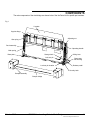
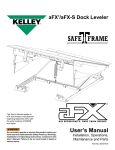
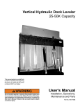
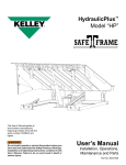
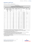
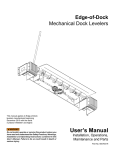
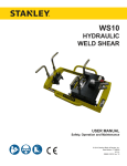
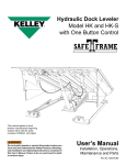
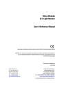
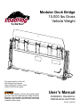
Modular Dock Bridge
15,000 lbs Gross
Vehicle Weight
This manual applies to the LHG
Dock Bridges manufactured
beginning May 2011 with the serial
number 61007869 and higher
Do not install, operate or service this product unless
you have read and understand the Safety Practices,
Warnings, and Installation and Operating Instructions
contained in this manual. Failure to do so could result
in death or serious injury.
User’s Manual
Installation, Operations,
Maintenance and Parts
Part No. 6006333H
Table of contents
Table of Contents .................................................... 2
Introduction . ............................................................ 2
Safety Signal Words................................................. 2
Safety Practices ...................................................... 3
Owner’s Responsibilities ......................................... 4
Components ............................................................ 5
Installation................................................................ 6
Operations.............................................................. 11
Lowering Dock Bridge...................................... 12
Storing Dock Bridge.......................................... 13
End Loading, Storing the Dock Bridge............. 14
Planned Maintenance............................................. 17
Adjustments............................................................ 19
Main Spring ........................................................... 19
Inspect Lip Latch ................................................... 20
Inspect Security Latch ........................................... 21
Troubleshooting Guide........................................... 22
Parts List................................................................ 24
Limited Warranty Information................................. 27
Corporate Contact ................................................. 28
INTRODUCTION
Welcome, and thank you for buying your LoadHog® dock bridge from 4Front Engineered Solutions, Inc.
This manual contains information that you need to operate and maintain the dock bridge safely. It also contains
a complete parts list and information about reordering replacement parts. Please read it before you use your
new dock bridge.
Safety Signal words
You may find safety signal words such as DANGER, WARNING, or CAUTION throughout this User’s Manual.
Their use is explained below:
This is the safety alert symbol. It is used
to alert you to potential personal injury
hazards. Obey all safety messages that
follow this symbol to avoid possible death or injury.
Indicates an imminently hazardous situation which, if
not avoided, will result in death or serious injury.
Indicates a potentially hazardous situation which,
if not avoided may result in minor or moderate
injury.
Indicates a potentially hazardous situation which,
if not avoided, could result in death or serious
injury.
Notice is used to address practices not related to
personal injury.
2
©2013 4Front Engineered Solutions, Inc.
6006333H — Loadhog Modular Dock Bridge
October 2013
SAFETY PRACTICES
Read these safety practices before installing, operating,
or servicing the dock bridges. Failure to follow the safety
practices could result in death or serious injury.
If you do not understand the instructions, ask your supervisor
to explain them to you or call local 4Front Engineered
Solutions distributor.
OPERATION:
Use of dock bridge restricted to trained operators.
Do not use this unit to service trailers outside of its intended
working range which is 6" above dock and 4" below dock.
Do not operate the dock bridge when anyone is in front of
it.
Follow procedures on placard(s) posted near dock bridge.
Stay clear of the dock bridge when it is moving.
KEEP HANDS CLEAR OF HINGES AT ALL TIMES. Do not
use hands to position dock bridge or lip, or to store dock
bridge. Use lifting handle furnished with dock bridge only to
position deck and lip.
Do not use the dock bridge if it appears damaged or does
not operate properly. Inform your supervisor immediately.
Do not stand in the driveway or on the bumper shelf between
the dock bridge and the backing truck.
Chock truck wheels or lock truck into place with truck
restraining device and set brakes before loading or
unloading.
Visually check that the lip is supported by the truck bed or
the dock bridge is fully lowered with the lip folded before
driving on the dock bridge.
Stay clear of the dock bridge unless the lip is supported by
the truck bed or the dock bridge is fully lowered. Unsupported
dock bridge can lower unexpectedly.
Store the dock bridge vertically with the storage latch
engaged and the lip extended vertically after use.
October 2013
Ensure lip avoids contact with trailer sides and cargo. If lip
does not lower to trailer bed, reposition trailer.
Move all equipment, material or people off the dock bridge
and store the dock bridge before allowing the truck to pull
out.
Do not use a fork truck or other material handling equipment
to lower the dock bridge.
Before chocking wheels, or engaging the vehicle restraint,
dump all air from the air ride suspensions and set the parking
brake.
Do not step on the bumper shelf until the trailer is securely
against the dock bumpers and chocked or secured with a
trailer restraint.
INSTALLATION, MAINTENANCE AND SERVICE:
Place barricades on the dock floor around the dock bridge
and in the driveway in front of the dock while installing,
maintaining or repairing the dock.
Do not operate the dock bridge when anyone is standing in
front of the dock or the dock bridge.
Before doing any maintenance, repair, or adjustment on the
dock bridge, store it in a vertical position with lip vertical, and
the lock-out pin engaged through the left base assembly.
Before you disable the spring counter balance system, insert
the lock-out pin through the left base assembly and secure
the lock-out pin with a padlock.
Never adjust or attempt to remove the springs when the dock
bridge is lowered. Never loosen or attempt to remove the nuts
on the anchor bolts when the dock bridge is lowered. The dock
bridge must be stored in a vertical position with the lock-out
pin engaged through the left base assembly.
Never lift the dock bridge by any other means than the
operating handle. If it does not lift, use a suitable lifting device
to raise and insert lock-out pin before troubleshooting.
Failure to follow these instructions could result in death or
serious injury to operators and/or bystanders.
6006333H — Loadhog Modular Dock Bridge
©2013 4Front Engineered Solutions, Inc.
3
OWNER’S RESPONSIBILITIES
The owner’s responsibilities include the following:
The owner should recognize the inherent danger of the
interface between dock and transport vehicle. The owner
should, therefore, train and instruct operators in the safe use
of dock bridges.
When a transport vehicle is positioned as closely as practical
to a dock bridge, there shall be at least 4” of overlap between
the front edge of the lip and the edge of the floor or sill of the
transport vehicle.
Nameplates, cautions, instructions and posted warnings shall
not be obscured from the view of operating or maintenance
personnel for whom such warnings are intended.
Manufacturer’s recommended periodic maintenance and
inspection procedures should be kept.
Dock bridges that are structurally damaged or have
experienced a sudden loss of support while under load,
such as when a transport vehicle is pulled out from under the
dock bridge, shall be removed from service, inspected by
the manufacturer’s authorized representative, and repaired
as needed before being placed back in service.
The owner shall see that all nameplates, caution and
instruction markings or labels are in place and legible and
that the appropriate operating and maintenance manuals
are provided to users.
Modifications or alterations of the dock bridge shall be made
only with written permission of the original manufacturer.
When industrial trucks are driven on and off transport
vehicles during the loading and unloading operation, the
brakes on the transport vehicle shall be applied and wheel
chocks or positive restraints that provide the equivalent of
wheel chocks engaged.
The dock bridge should never be used outside its vertical
working range or outside the manufacturer’s labeled
rated capacity. It must also be compatible with the loading
equipment and other conditions relating to the dock.
4
©2013 4Front Engineered Solutions, Inc.
6006333H — Loadhog Modular Dock Bridge
October 2013
COMPONENTS
The main components of the dock bridge are shown below. See the Parts List for specific part numbers.
Fig. 1
Lip plate
Lip plate hinge
Adjusting nut
Gas spring
Deck assembly
Operating handle
Main spring
Storage latch
Base plate
Lifting lever
Lock-out pin
Base ramp
side housing
Lock-out pin location
Release pedal
Security latch
Bumper assembly
Bumper bridge
October 2013
6006333H — Loadhog Modular Dock Bridge
©2013 4Front Engineered Solutions, Inc.
5
INSTALLATION
INSTALLATION
Before installing the dock bridge, read and follow the
Safety Practices on page 3. Failure to follow the safety
practices could result in death or serious injury.
Dock check
1. Determine the desired location of the dock bridge. Door
opening width recommendation is 8' for 6' wide model,
9' for 6'-6" wide model and 10' for 7' wide model.
Dock bridge check
1. Visually check that the dock bridge is not damaged.
NOTE:
Dock bridges may ship in pairs, examine both dock bridges
carefully.
NOTE:
Front, left and right directions are determined when standing
on the dock and looking out of the doorway. (Same orientation
as a truck backed into the dock.)
1. Mark centerline “A” on the dock floor perpendicular to
the dock face at the center of the desired dock position.
Mark a line “B” perpendicular to the centerline 18-9/16"
from the dock face. See Fig. 2.
NOTE:
The handle side spring cover should have at least 4" from
the door frame to the outside edge of the spring cover for
proper handle clearance from the door frame or nearest
obstruction. See Fig. 2.
Fig. 2
Align with center marks
18-9/16"
Right
Left
Front
CL
Line “A”
Line “B”
36-1/8" (6' model)
39-1/8" (6'-6" model)
42-1/8" (7' model)
8" min.
to door
frame
6
©2013 4Front Engineered Solutions, Inc.
6006333H — Loadhog Modular Dock Bridge
October 2013
INSTALLATION, continued
2. Check that the floor is flat in the base mounting area
(24" x 86") for width of the dock bridge. Remove any
bumps in the concrete. If the floor is higher in the center
it may interfere with proper operation. Continue with the
installation of the dock bridge but refer to step 11 when
inspecting for proper operation.
Wear proper eye and hand protection when cutting steel
banding.
3. Carefully cut the steel banding and remove the bumpers,
bumper shelf, operating handle and hardware tube from
the dock bridge. See Fig. 3.
Fig. 3
4. Use a 15/16" socket wrench to remove the 5/8" nuts (4
each side) from the bolts securing the dock bridge to the
wood shipping skids, and the two bolts from the lip plate
brace. Discard fasteners. See Fig. 3.
Inadequate lifting equipment or practices can cause a
lifted load to fall unexpectedly. Make sure lifting chain
or other lifting devices are in good condition and have
a rated capacity of at least 3500 lbs. for the lifting angle
used. Never allow anyone to stand on or near dock
bridge when it is being lifted or placed onto the dock
floor. Stand clear of the dock bridge when it is being
placed onto the dock floor. Failure to follow this warning
can allow the dock bridge to fall, tip, or swing into people,
resulting in death or serious injury.
NOTE:
Handle one dock assembly at a time.
Lip plate brace
Steel
banding
Shipping
skid
Bolts
5. Install a load centering eye bolt through the lip plate of
the dock bridge. The dock bridge should not be lifted in
any other manner.
6. Place the dock bridge in the desired position at the dock
with the center of the deck aligned with the center of the
opening and the front edge of the base plates 18-9/16"
back from curb angle See Fig. 2.
October 2013
6006333H — Loadhog Modular Dock Bridge
©2013 4Front Engineered Solutions, Inc.
7
INSTALLATION, continued
Fig. 4
Do not remove the lock-out pin from the base assembly
until the dock bridge has been secured to the dock floor.
Failure to follow this warning can allow the dock bridge
to fall, resulting in death or serious injury.
8. Using a 3/4" bit and the holes in the base plates as a
guide, drill four holes at least 5-1/2" deep into the dock
floor. Blow out or vacuum drilling dust from hole. Secure
the dock bridge to the floor with the four 3/4" × 5-1/2"
anchors and hardware provided. Torque the nuts to 110
ft-lb. See Fig. 4.
5-1/2" min.
3/4"
Improper installation of anchoring devices or installation
into aged or unsound concrete could result in death or
serious injury.
9. Install a steel cap to plug the hole in each side frame.
See Fig. 5.
10. Remove the lock-out pin from the left base assembly and
store it in the socket on the deck.
11. Inspect the dock face for installation of the bumpers.
Ensure that the dock face is clear 56" each side of the
dock centerline and 14" below the dock floor.
Fig. 5
Do not stand in front of the dock bridge when removing
the lock-out pin. Failure to follow the safety practices
could result in death or serious injury.
12. Place the operating handle in the socket on the left side
of the dock bridge. Step on the latch release pedal and
gently push the dock bridge forward. It should lower to
the fully lowered position.
13. Cycle the dock bridge going through the operational
steps described on pages 11 through 16. Refer to
the troubleshooting guide on pages 22 and 23 if any
operational problems are encountered.
8
©2013 4Front Engineered Solutions, Inc.
Latch
release
pedal
6006333H — Loadhog Modular Dock Bridge
October 2013
INSTALLATION, continued
Extended springs contain stored energy. Never attempt
to adjust or remove the springs when the dock bridge is
lowered. Never loosen or attempt to remove the nuts on
the anchor bolts when the dock bridge is lowered. The
dock bridge must be stored in a vertical position with the
lock-out pin engaged through the left base assembly.
14. Mark a line on the dock floor at each side of the dock
bridge. Raise the dock bridge to the stored vertical
position and engage the lock-out pin.
15. Measure from the centerline “A” to each of the lines
marked in step 14. Mark a new centerline if the
dimensions are not equal. Mark two vertical lines “E” on
the dock floor 43" each side of the centerline.
16. Locate bumpers as shown in Fig. 6. 6' and 6'-6" models
will position the top plate flush with the dock floor. See
Fig. 6. 7' models will position the top of the positioning
tab flush with the dock floor. See Fig. 6. A positioning tab
is provided on the 7' assembly. Note that there are right
and left bumpers and the brackets on the side must be
toward the center of the dock. See Fig. 6. Secure each
bumper to the dock face with four 3/4" × 5-1/2" anchor
bolts provided. Torque to 110 ft-lb.
Fig. 6
7' models only
Positioning tab
Anchor bolts
(4 per bumper)
86"
October 2013
CL
43"
6006333H — Loadhog Modular Dock Bridge
©2013 4Front Engineered Solutions, Inc.
9
INSTALLATION, continued
17. Using the four 1/2" bolts and hardware supplied, attach
the shelf to the bumpers with the lip edge out. See Fig.
7.
Fig. 7
1/2" UNC x 1-1/2 bolt (4)
18. Permanently mount the dock bridge warning and
operating placard on the wall nearest to the dock bridge.
See Fig. 8.
19. Perform the quarterly maintenance steps on page 17 in
this manual.
Center of dock
Fig. 8
Placard
48"
10 ©2013 4Front Engineered Solutions, Inc.
6006333H — Loadhog Modular Dock Bridge
October 2013
OPERATIONS
Before operating the dock bridge, read and follow the
Safety Practices on page 3. Use of dock bridge restricted
to trained operators. Follow procedures on placard
posted near dock bridge.
DO NOT USE DOCK BRIDGE IF IT LOOKS BROKEN,
OR DOES NOT SEEM TO WORK RIGHT. Inform your
supervisor immediately.
Before chocking wheels or engaging vehicle restraint,
dump air from air ride suspensions and set parking
brake.
Always be certain that the truck is properly restrained,
before loading or unloading. VISUALLY INSPECT
vehicle restraint to make sure truck does not pull away
unexpectedly. Failure to do so could result in death or
serious injury.
Ensure lip avoids trailer sides and cargo when deck
is lowered. If the lip does not lower to the trailer bed,
reposition trailer.
Visually check that the lip is supported by the truck
bed or the dock bridge is fully lowered to the dock floor
with the lip folded before driving or walking on the dock
bridge.
INTRODUCTION
The LoadHog® dock bridge is designed to span and
compensate for space and height differences between a
loading dock and freight carrier to allow safe, efficient freight
transfers.
The dock bridge is spring counter balanced to allow easy
manual lowering and raising.
The dock bridge is stored vertically with the lip extended.
A mechanical latch holds the dock bridge in the stored
position.
Stepping on the foot pedal releases the latch and allows
the dock bridge to be pushed forward so it will lower to the
working position.
The dock bridge is downwardly biased in the working
position.
A security latch prevents the dock bridge from inadvertently
raising above the working range.
After loading, raising the operating handle releases the
security latch and raises the dock bridge.
For end loads the lip can be manually lowered by moving the
operating handle to the socket in the lip plate.
Always return the dock bridge to its latched vertical
stored position with the lip extended vertically before
allowing the truck to leave the dock.
Never lift the dock bridge by any other means than
the operating handle. If it does not lift, use a suitable
lifting device to raise and insert lock-out pin before
troubleshooting.
Failure to follow these instructions could result in death
or serious injury to operators and/or bystanders.
NOTE:
If the truck unexpectedly pulls away leaving the dock bridge
unsupported, the dock bridge will fall to full below dock
level.
October 2013
6006333H — Loadhog Modular Dock Bridge
©2013 4Front Engineered Solutions, Inc.
11
OPERATIONS,
continued
Use these instructions for normal operations.
Always secure the truck with a vehicle restraint or wheel
chocks before operating the dock bridge. Do not operate
dock bridge with anyone standing on or in front of it.
Do not lift the dock bridge lip by hand.
Before doing any maintenance, repair, or adjustment
on the dock bridge, store it in a vertical position with
lip vertical, and the lock-out pin engaged through the
left base assembly.
Always keep hands and feet clear of all moving parts.
Always return the dock bridge to its latched vertical
stored position with the lip extended vertically before
allowing the truck to leave the dock.
Lowering the Dock bridge
1. Before operating the dock bridge, secure the truck with
a vehicle restraint or wheel chocks.
2. To lower the dock bridge, step on the latch release
pedal and gently push the dock bridge forward. See
Fig. 9.
Fig. 9
3. The dock bridge should lower gently to the working
position with the lip supported by the freight carrier. If it
does not lower all the way, walk on the deck to lower
it. See Fig. 10.
Fig. 10
12 ©2013 4Front Engineered Solutions, Inc.
6006333H — Loadhog Modular Dock Bridge
October 2013
OPERATIONS, continued
Storing the Dock bridge
1. To return the dock bridge to the stored vertical position,
raise the operating handle by gently stepping on the
bar protruding from the side of the operating handle
housing. See Fig. 11.
Fig. 11
2. Pull firmly on the operating handle to raise the dock
bridge to the stored position. The dock bridge will raise
and the storage latch will automatically engage. See Fig.
12.
NOTE:
Operating handle contains ratchet feature. While lifting deck,
push forward on the operating handle to obtain additional
lifting advantage and then pull firmly.
3. Push the operating handle forward and it will lock in
the vertical stored position. See Fig. 13.
Fig. 12
Fig. 13
October 2013
6006333H — Loadhog Modular Dock Bridge
©2013 4Front Engineered Solutions, Inc.
13
OPERATIONS,
continued
Use these instructions when end loading a truck.
End Loading
1. Pull the operating handle straight up to remove it from
the lifting lever. Then insert the operating handle into the
socket at the left side of the lip. See Fig. 14.
Fig. 14
2. Lift the operating handle up until the lip moves forward
and the lip latch disengages. The lip will fall slowly to the
retracted position. See Fig. 15.
3. Remove the operating handle from the lip and replace it
in the lifting lever. Then step on the latch release pedal
and gently push the dock bridge forward. It should
fall gently to the working position. See Fig. 16.
4. If the dock bridge does not fall all the way, walk on the
deck to lower it. See Fig. 17.
Fig. 15
Fig. 16
14 ©2013 4Front Engineered Solutions, Inc.
6006333H — Loadhog Modular Dock Bridge
October 2013
OPERATIONS, continued
Fig. 17
End Loading, Storing the Dock Bridge
1. To return the dock bridge to the stored vertical position,
raise the operating handle by gently stepping on
the bar protruding from the side of the lifting handle
housing. See Fig. 18.
Fig. 18
2. Pull firmly on the operating handle to raise the dock
bridge to the stored position. The dock bridge will raise
and the storage latch will automatically engage. See Fig.
19.
NOTE:
Operating handle contains ratchet feature. While lifting deck,
push forward on the operating handle to obtain additional
lifting advantage and then pull firmly.
Fig. 21
October 2013
6006333H — Loadhog Modular Dock Bridge
©2013 4Front Engineered Solutions, Inc.
15
OPERATIONS, continued
storing the lip
1. Pull the operating handle straight up to remove it from
the lifting lever and insert it into the socket at the left side
of the lip. See Fig. 20.
Fig. 20
2. Pull the operating handle back until the lip rotates 60º
allowing the gas springs to lift the lip to its final vertical
position. See Fig. 21.
3. Remove the operating handle from the lip. Replace the
handle in the lifting lever. See Fig. 22.
Fig. 21
Slow
Fast
Fig. 22
16 ©2013 4Front Engineered Solutions, Inc.
6006333H — Loadhog Modular Dock Bridge
October 2013
PREVENTIVE MAINTENANCE
Before servicing the dock bridge, read and follow the
Safety Practices on page 3 and the operations sections
of this manual. Failure to follow the safety practices
could result in death or serious injury.
Before doing any maintenance, repair, or adjustment
on the dock bridge, store it in a vertical position with lip
vertical, and the lock-out pin engaged through the left
base assembly.
Extended springs contain stored energy. Never attempt
to adjust or remove the springs when the dock bridge is
lowered. Never loosen or attempt to remove the nuts on
the anchor bolts when the dock bridge is lowered. The
dock bridge must be stored in a vertical position with
the lock-out pin engaged through the left base assembly.
Weekly
•Clean debris from area around the dock bridge.
Quarterly
• Inspect all warning labels and placards. See page 18.
Replace as necessary.
• Ensure that nothing is in the way of the dock bridge if it
lowers. With the dock bridge in the vertical stored position,
gently push the dock bridge forward. The dock bridge
should not fall forward. If it does then the storage latch
is not engaging. Inspect the latch to ensure that it rotates
freely, and remove any debris from the latch area. If latch
is damaged it must be replaced.
• Inspect and lubricate all points as shown in Fig. 23 on
page 18.
• Lubricate the lip hinge lugs with light oil or chain lube spray.
Do not over lubricate. Use the operating handle to extend
and retract the lip several times. See page 14. Wipe off
excess lubricant.
• Lubricate the ball joints on the gas springs with light oil. Do
not over lubricate. Wipe any excess oil from gas springs.
• Ensure that nothing is in the way of the dock bridge as
it lowers. Step on the latch release pedal and gently
push the dock bridge forward. It should lower toward the
working position and almost stop as it approaches the
working position. It is acceptable if the dock bridge stops
above the working position as a slightly harder push will
ensure that the dock bridge will fully lower. However
when the dock bridge is in the working range (6" above
and 4" below dock floor), it must always lower all the way
to the dock floor. If the dock bridge falls heavily to the
working position, increase the spring tension. If the dock
bridge does not always lower when in the working range
decrease the spring tension. See Adjustments on page 19.
After adjusting the spring, repeat the test.
• With the dock bridge lowered and the lip extended, lift up
on the end of the lip. The dock bridge should feel heavy
and move downward when the lip is released between
0" and 20" above dock. If the dock bridge raises at any
position, the security latch is not properly engaged. See
Adjustments on page 21 for corrective action.
• Inspect dock bumpers. Four inches (4") of bumper
protection is required. Worn, torn, loose or missing
bumpers must be replaced.
October 2013
6006333H — Loadhog Modular Dock Bridge
©2013 4Front Engineered Solutions, Inc.
17
Planned mAINTENANCE, continued
Every 90 days (quarterly) inspect all safety labels and tags
to ensure they are on the dock bridge and are easily legible.
If any are missing or require replacement, please contact
your distributor.
Fig. 23
(ball joints)
(ball joints)
6002120
6002121
Legend
Symbol
Description
Lubricant - Oil
Light oil - SAE 30
OPERATING
INSTRUCTIONS
Lubricant - Grease
Lithium grease
NLGI #2
6002199
Lubricant - Chain
Chain lubricant LPS 2
or equivalent
Visually Inspect
(Oil leaks)
18 ©2013 4Front Engineered Solutions, Inc.
Warning and operation placard
(mounted on wall near dock bridge)
6006333H — Loadhog Modular Dock Bridge
October 2013
ADJUSTMENTS
Use these instructions to adjust the dock bridge.
Before doing any maintenance, repair, or adjustment
on the dock bridge, store it in a vertical position with lip
vertical, and the lock-out pin engaged through the left
base assembly.
Before servicing the dock bridge, read and follow the
Safety Practices on page 3 and the operations sections
of this manual. Failure to follow the safety practices
could result in death or serious injury.
Extended springs contain stored energy. Never attempt
to adjust or remove the springs when the dock bridge is
lowered. Never loosen or attempt to remove the nuts on
the anchor bolts when the dock bridge is lowered. The
dock bridge must be stored in a vertical position with the
lock-out pin engaged through the left base assembly.
Before servicing the dock bridge, always position traffic
cones or a barricade behind the dock bridge to warn
fork truck operators and pedestrians away from the
dock bridge.
Before you disable the spring counter balance system,
insert the lock-out pin through the left base assembly
and secure the lock-out pin with a padlock.
Always position traffic cones or a barricade in front of
the dock bridge to warn against truck traffic.
Always notify a foreman or supervisor that you are
working on the equipment.
The dock bridge is counter balanced by two springs, one on
each side. Spring tension is adjusted by turning the nut on
the eyebolt at the top of each spring as shown in Fig. 24.
ADJUST MAIN SPRINGS
Ensure that nothing is in the way of the dock bridge as it
lowers. Step on the latch release pedal and gently push
the dock bridge forward. It should lower toward the working
position and almost stop as it approaches the working
position. It is acceptable if the dock bridge stops above the
working position as a slightly harder push will ensure that
the dock bridge will fully lower. However when the dock
bridge is in the working range (6" above and 4" below dock
floor), it must always lower all the way to the dock floor. If the
dock bridge falls heavily to the working position, increase
the spring tension. If the dock bridge does not always lower
when in the working range decrease the spring tension.
After adjusting the spring, repeat the test to ensure proper
operation.
Fig. 24
Adjusting nut
Dampening
sleeve
Eye bolt
Main spring
To adjust the spring tension, turn the adjusting nut on both
springs one half turn. Both springs should be adjusted
equally.
Lock-out pin
October 2013
6006333H — Loadhog Modular Dock Bridge
©2013 4Front Engineered Solutions, Inc.
19
ADJUSTMENTS, continued
LIP ASSIST — GAS SPRING
The LoadHog is fitted with two gas springs that support the lip
during operation. The lip must remain firmly extended when
lowered into the truck. Inspect the gas spring for oil leakage
or loss of pressure. Under normal operation the gas spring
assist the lip extension and will lift the lip from 60º to vertical
position. The lift should be a slow rate under control.
INSTALLATION
Proper installation requires the gas spring to be installed with
a pre load. Install the gas spring (cylinder side) to the lower
mounting hole of the gas spring mounting bracket and tighten.
The upper mounting bracket must be installed with the upper
bolt first then with the use of a 1/2" sq. drive ratchet or breaker
bar, rotate the bracket downward compressing the gas spring.
Insert the lower bracket bolt and tighten.
NOTE:
See proper disposal procedures on page 21.
Fig. 25
Ratchet
Bolt
Gas spring
cylinder side
20 ©2013 4Front Engineered Solutions, Inc.
6006333H — Loadhog Modular Dock Bridge
October 2013
ADJUSTMENTS, continued
INSPECT SECURITY LATCH
The security latch is mounted on the left end of the dock
bridge pivot shaft. The security latch is spring biased to
rotate in a clockwise direction and should pivot freely. Move
the security latch forward by hand and ensure that it rotates
backward against the stop on the base plate. If the security
latch does not rotate backward, inspect to see if the spring
is missing and replace the spring if required. If the security
latch does not rotate freely, lubricate the shaft. See Fig. 26.
Fig. 26
Spring link
Lock-out pin
The security latch engages the top of the spring link when
the dock bridge is in the working range. If the dock bridge
becomes upward biased when in the working range, lower
the dock bridge and inspect to see if the security latch
engages the top of the spring link. If the security latch does
not engage properly, replace it.
Handling and disposal of gas springs
• Gas springs are under pressure. They must be drained of
oil prior to disposal.
Security latch
Security latch spring
Deck pivot
pin shaft
• Gas springs are filled with oil. Waste disposal only through
raw materials trade or special refuse points.
• Do not dispose of gas springs in household refuse. Oil
must not get into soil or water.
Fig. 27
3/4"
NOTE:
For waste removal of gas spring the following work must be
performed in compliance with the accidental prevention and
environment protection regulations.
Wear proper eye protection.
5.Collect the oil and dispose of as specified by the relevant
waste disposal regulations.
1.Clamp gas spring in a vice.
2.Drill open units at the specified point with an approximately
1/8" drill bit to allow the gas to escape. Shield the drilling
point to prevent splashes of oil and debris. The hole must
be drilled to a depth of about 3/8". Make a hole about 3/4"
away from bottom of pressure tube as show in Fig. 27.
6.Dispose of the cylinder as metal waste.
3.The gas spring oil is hydraulic oil and can be disposed of
with motor oil/transmission lubricant according to the local
waste disposal regulations.
4.Drain the oil from the gas spring by pumping the piston
rod in and out several times.
October 2013
6006333H — Loadhog Modular Dock Bridge
©2013 4Front Engineered Solutions, Inc.
21
TROUBLESHOOTING GUIDE
Use the Troubleshooting Guide if ever the dock bridge fails to perform properly.
Before doing any maintenance, repair, or adjustment on
the dock bridge, store the leveler in a vertical position
with lip vertical, and the lock-out pin engaged through
the left base assembly.
Problem
Before servicing the dock bridge, read and follow the
Safety Practices on page 3 and the Operating Instruction
section in this manual.
Never lift the dock bridge by any other means than
the operating handle. If it does not lift, use a suitable
lifting device to raise and insert lock-out pin before
troubleshooting.
Possible Cause
1)Lip retracts before the dock bridge
is fully lowered.
Solution
a)Gas spring bracket loose.
a)Inspect the upper gas spring
mounts for loose or missing
fasteners. Replace as required.
b) Gas spring failure(s).
b) Replace gas spring(s).
2)Lip does not stay extended when
the dock bridge is in down position.
a)Lip gas spring(s) is worn or
damaged.
a) Replace gas spring(s).
3)Lip raises too slowly or stops part
way.
a) Lip hinge requires lubrication.
a) Lubricate lip hinge.
b)Lip gas spring(s) is damaged or
binding.
b) Replace gas spring.
4) Dock bridge falls too fast.
a) Main springs require more tension.
a) Adjust main spring tension.
See page 19.
5) Dock bridge raises from truck bed.
a)Main springs have too much
tension.
a) Adjust main spring tension.
See page 19.
b) Security latch is not engaging.
b)Inspect hold down for free
movement and ensure security
latch spring is present. Lubricate
shaft and replace security latch
and spring if required.
a)Security latch does not disengage.
a) Operating handle does not
engage security latch. Inspect
handle assembly and security
latch assembly. Replace any
damaged parts.
b)Main springs require more tension
or a spring or chain is broken.
b)Adjust main springs or replace
broken spring or chain.
See page 19.
6)Dock bridge cannot be raised from
the truck bed.
22 ©2013 4Front Engineered Solutions, Inc.
6006333H — Loadhog Modular Dock Bridge
October 2013
TROUBLESHOOTING GUIDE, continued
Before doing any maintenance, repair, or adjustment on
the dock bridge, store the leveler in a vertical position
with lip vertical, and the lock-out pin engaged through
the left base assembly.
Problem
Before servicing the dock bridge, read and follow the
Safety Practices on page 3 and the Operating Instruction
section in this manual.
Never lift the dock bridge by any other means than
the operating handle. If it does not lift, use a suitable
lifting device to raise and insert lock-out pin before
troubleshooting.
Possible Cause
Solution
7) Dock bridge does not fully raise.
a) Debris caught between coils of the
main spring.
a) Partially lower the dock bridge and
remove debris from spring coils.
8) Dock bridge does not fully lower.
a)Debris on dock floor in front of dock
bridge.
a)Raise the dock bridge to the
latched vertical stored position and
remove debris.
9) Dock bridge bounces/raises off truck
bed during loading and unloading.
a)Lip not being held tight to deck.
a)Inspect the lip and gas spring(s).
If the gas spring is damaged or
lacking pressure the lip will not
remain extended. Replace the
gas spring. See page 20.
b)Main springs require less tension.
b)Adjust (loosen) eyebolt(s) 1/2~1
turn. Test performance. Repeat.
a)Deck weight is resting on latch arm.
a)Pull back on deck while stepping
on release pedal. Then push
forward.
10) Foot pedal release too hard to
depress when lowering deck.
October 2013
6006333H — Loadhog Modular Dock Bridge
©2013 4Front Engineered Solutions, Inc.
23
DOCK BRIDGE PARTS LIST
Use this Parts List to determine the correct replacement part(s) for your dock bridge.
Fig. 28
To ensure proper function, durability and safety of the
product, only 4Front original replacement parts must be
used. Incorporation of replacement parts or modifications
that weaken the structural integrity of the product, or in a
way alter the product from its normal working condition
at the time of purchase from 4Front Engineered Solutions
could result in product malfunction, breakdown,
premature wear, death or serious injury.
36
32
30
29
35
Fig. 28
23
19
28
39
17
47
16
37
21
20
7
14
22
38
6
52
15
2
1
9
26
33
13
34
31
12
24 ©2013 4Front Engineered Solutions, Inc.
6006333H — Loadhog Modular Dock Bridge
October 2013
DOCK BRIDGE PARTS LIST, continued
Fig. 29
18
10
41
11
2
40
3
50
44
27
49
47
2
43
55
1
45 53
43
51
46
56
47
24
45
54
8
25
Part Number
Item Qty
Part Description
LH6LH6-6LH7
1
5
Nylock nut - 1/2-13 unc
214505
214505
214505
2
13
Washer 1/2 - 0.562Id x 1.375 Od
234121
234121
234121
3
2
Hole plug, 2"
6002112
6002112
6002112
4
1
Deck assembly 6006104
6006111
6006117
5
1
Operation placard (not shown)
6002199
6002199
6002199
6
1
Truarc extr. Klipring, 5/8" thin
049060
049060
049060
7
2
Nylock nut - 3/4-10 unc
214558
214558
214558
8
8
Socket head cap screw 3/4"-10unc x 3 1/2"
212328
212328
212328
9
2
Extension spring-l800-cp
333054
333054
333054
10
2
Cam cover paint assy
6002024
6002024
6002024
11
4
Hex socket button cap screw 1/2 - 13 x 7/8
6002078
6002078
6002078
12
2
Pin, cam link
6002099
6002099
6002099
13
2
Spring-cam link assy
6002170
6002170
6002100
14
1
Plate, latch bar
6002106
6002106
6002106
15
1
Plate, handle ratchet
6002107
6002107
6002107
October 2013
6006333H — Loadhog Modular Dock Bridge
©2013 4Front Engineered Solutions, Inc.
25
DOCK BRIDGE PARTS LIST, continued
Part Number
Item Qty
Part Description
LH6LH6-6LH7
16
2
Label, warning, vertical
6002120
6002120
6002120
17
1
Label ,warning, horizontal
6002121
6002121
6002121
18
2
Label, logo and warning stripe
6002123
6002123
6002123
19
1
Label, logo, back
6002124
6002124
6002124
20
1
Safety pin assy
6002155
6002155
6002155
21
1
Serial tag
6009761
6009761
6009761
22
2
Eye bolt, 3/4-10, unc
6002419
6002419
6002419
23
2
Gas spring
6006107
6006107
6006107
24
1
Bumper assy, RH, 26"
6008984
6008984
6008992
25
1
Bumper assy, LH, 26"
6008983
6008983
6008991
26
1
Handle base weldment
6010937
6010937
6010937
27
1
Pre-ramp assembly
6006103
6006110
6006116
28
1
Lip assy
6006105
6006112
6006118
1
Cut down lip assy
6006525
6006526
—
29
1
Lip rod 6006913
6006914
6006915
30
4
Bolt, hex 3/8-16 unc x 1 1/4 lg
000357
000357
000357
31
1
Security latch weldment
6006108
6006108
6006128
32
4
Nylock nut - 3/8-16 unc
214538
214538
214538
33
2
Bearing, deck pivot
6006138
6006138
6006138
34
1
Spring, security latch lh-e3
6006161
6006161
6006161
35
4
Nylock nut - m10x1.5 (metric)
6006234
6006234
6006234
36
2
Lip lug gas spring mount top
6006916
6006916
6006916
37†
1
Assembly, lift handle
6010932
6010932
6010932
38
1
Handle assembly
6010934
6010934
6010934
39
1
Handle, grip, yellow
6007550
6007550
6007550
40
1
Base assembly, lh
6006102
6006102
6006115
41
1
Base assembly, rh
6006101
6006101
6006114
42*
1
Bumper assembly, rh, 13"
6008602
6008602
6008606
43
2
Db13 moulded bumper - for 13" bumpers
391811
391811
391811
4
Db13 moulded bumper - for 26" bumpers
391811
391811
391811
44
1
Frame paint assy, bumper, rh, 13" bumper
6008604
6008604
6008608
45
4
Washer 3/4 - 0.812Id x 2 od - for 13" bumpers
234141
234141
234141
8
Washer 3/4 - 0.812Id x 2 od - for 26" bumpers
234141
234141
234141
46
2
Bolt, hex 3/4-10 unc - 3 1/2" lg - gr
212328
212328
212328
47
12
Anchor bolt, 3/4 x 5 1/2 - for 13" bumpers
6001187
6001187
6001187
20
Anchor bolt, 3/4 x 5 1/2 - for 26" bumpers
6001187
6001187
6001187
48**
1
Bumper assembly, lh, 13"
6008601
6008601
6008605
49
1
Plate, bridge, bumper
6002111
6002111
6002111
50
4
Bolt, hex 1/2-13 unc - 1.25 - Gr5
212204
212204
212204
51
1
Frame paint assy, bumper, lh , 13" bumper
6008603
6008603
6008607
52
1
1/2-13x1.5 HB
6006479
6006479
6006479
53
2
Steel face assy, bumper, 13" (optional)
6006774
6006774
6006774
54
1
Frame paint assy, bumper, lh , 26" bumper
6008985
6008985
6008993
55
1
Frame paint assy, bumper, rh , 26" bumper
6008986
6008986
6008994
56
2
Steel face assy, bumper, 26"
6002188
6002188
6002188
*Includes items 43, 44, 45 and 46.
**Includes items 43, 45, 46 and 51.
†Includes items 38 and 39.
26 ©2013 4Front Engineered Solutions, Inc.
6006333H — Loadhog Modular Dock Bridge
October 2013
LIMITED WARRANTY INFORMATION
4Front Engineered Solutions, Inc. warrants that this DOCK BRIDGE will be free from flaws in material and workmanship
under normal use for a period of one (1) year from the earlier of 1) 60 days after the date of initial shipment by 4Front
Engineered Solutions, Inc., or 2) the date of installation of the DOCK BRIDGE by the original purchaser, provided that the
owner maintains and operates the DOCK BRIDGE in accordance with this User’s Manual.
Main Spring Warranty — All main springs are warranted to cover the cost of replacement parts and freight only for an
extended period of four (4) years after the initial 1 yr. warranty period.
Parts warranty — All spare or replacement parts are warranted to cover the cost of replacement parts and freight only for
ninety (90) days from the date of shipment.
In the event that this DOCK BRIDGE proves deficient in material or workmanship within the applicable limited warranty
period, 4Front Engineered Solutions, Inc. will, at its option:
1. Replace the DOCK BRIDGE, or the deficient portion of either, without charge to the owner; or
2. Alter or repair the DOCK BRIDGE, on site or elsewhere, without charge to the owner.
The limited warranty stated in the preceding paragraph IS EXCLUSIVE AND IT IS IN LIEU OF ANY OTHER GUARANTEES
AND WARRANTIES, EXPRESS OR IMPLIED. The limited warranty does not cover any failure caused by improper
installation, abuse, negligence, or failure to maintain and adjust the DOCK BRIDGE properly. Parts requiring replacement due
to damage resulting from vehicle impact, abuse, or improper operation are not covered by this warranty. 4Front Engineered
Solutions, Inc. disclaims any responsibility or liability for any loss or damage (including, without limitation, direct, indirect or
consequential damages, or lost profits or production time) that results from the use of unauthorized replacement parts or
modification of the DOCK BRIDGE. 4Front Engineered Solutions, Inc. sole obligation with regard to a DOCK BRIDGE that
proves to be deficient in material or workmanship shall be as set forth in its standard warranty above (i.e., 4Front Engineered
Solutions, Inc. will, at its option, repair or replace the DOCK BRIDGE or portion thereof, without charge to the purchaser).
This limited warranty does not cover any failure caused by improper installation, abuse, negligence, or failure to properly
maintain and adjust the DOCK BRIDGE. This limited warranty will be void or of no effect if the original purchaser does
not notify 4Front Engineered Solutions, Inc.’s warranty department within ninety (90) days after the product deficiency is
discovered. Parts requiring replacement due to damage resulting from vehicle impact, abuse, or improper operation are not
covered by this warranty. 4Front Engineered Solutions, Inc. disclaims any responsibility or liability for any loss or damage
that results from the use of unauthorized replacement parts or modification of the DOCK BRIDGE.
THERE ARE NO WARRANTIES, EXPRESS OR IMPLIED, WHICH EXTEND BEYOND THE DESCRIPTION ON THE
FACE HEREOF, AND THERE IS NO WARRANTY OF MERCHANTABILITY OR OF FITNESS FOR A PARTICULAR
PURPOSE.
4Front Engineered Solutions, Inc. warranties extend only to the DOCK BRIDGE itself.
4Front Engineered Solutions, Inc. DISCLAIMS all warranties, express or implied, responsibility or liability for loss
or damage of any kind associated with the installation or maintenance of the DOCK BRIDGE, including any liability
for premature product wear, product failure, property damage or bodily injury arising from improper installation or
maintenance of the DOCK BRIDGE.
October 2013
6006333H — Loadhog Modular Dock Bridge
©2013 4Front Engineered Solutions, Inc.
27
Please direct questions about your dock bridge to your local distributor, or to 4Front Engineered Solutions, Inc.
Corporate Head Office:
Your local distributor is:
1612 Hutton Dr. Suite 140
Carrollton, TX. 75006
Tel. (972) 466-0707
Fax (972) 323-2661
www.theloadhog.com
LoadHog™
Powerfully Simple®
4Front Engineered Solutions®
©2013 4Front Engineered Solutions, Inc.
Part No. 6006333H