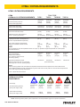
1
GR30
HYDRAULIC
GRINDER
USER MANUAL
Safety, Operation and Maintenance
© 2014 Stanley Black & Decker, Inc.
New Britain, CT 06053
U.S.A.
49237 2/2015 Ver. 5
DECLARATION OF CONFORMITY
DECLARATION OF CONFORMITY
ÜBEREINSTIMMUNGS-ERKLARUNG
DECLARATION DE CONFORMITE CEE
DECLARACION DE CONFORMIDAD
DICHIARAZIONE DI CONFORMITA
Hydraulic Tools
______________________________________________________________________
I, the undersigned:
Ich, der Unterzeichnende:
Je soussigné:
El abajo firmante:
lo sottoscritto:
Weisbeck, Andy
Surname and First names/Familiennname und Vornamen/Nom et prénom/Nombre y apellido/Cognome e nome
hereby declare that the equipment specified hereunder:
bestätige hiermit, daß erklaren Produkt genannten Werk oder Gerät:
déclare que l’équipement visé ci-dessous:
Por la presente declaro que el equipo se especifica a continuación:
Dichiaro che le apparecchiature specificate di seguito:
Grinder, Hydraulic
1.
Category:
Kategorie:
Catégorie:
Categoria:
Categoria:
2.
Make/Marke/Marque/Marca/Marca
3.
Type/Typ/Type/Tipo/Tipo:
4.
Serial number of equipment:
Seriennummer des Geräts:
Numéro de série de l’équipement:
Numero de serie del equipo:
Matricola dell´attrezzatura:
Stanley
GR3070101
All
Has been manufactured in conformity with
Wurde hergestellt in Übereinstimmung mit
Est fabriqué conformément
Ha sido fabricado de acuerdo con
E’ stata costruita in conformitá con
Directive/Standards
Richtlinie/Standards
Directives/Normes
Directriz/Los Normas
Direttiva/Norme
No.
Nr
Numéro
No
n.
Approved body
Prüfung durch
Organisme agréé
Aprobado
Collaudato
EN ISO
ISO
ISO
Machinery Directive
3744:2010
11148-7:2012
28927-4:2010
2006/42/EC:2006
Self
Self
Self
Self
5.
Special Provisions:
None
Spezielle Bestimmungen:
Dispositions particulières:
Provisiones especiales:
Disposizioni speciali:
6.
Representative in the Union: Patrick Vervier, Stanley Dubuis 17-19, rue Jules Berthonneau-BP 3406 41034 Blois Cedex, France.
Vertreter in der Union/Représentant dans l’union/Representante en la Union/Rappresentante presso l’Unione
Done at/Ort/Fait à/Dado en/Fatto a Stanley Hydraulic Tools, Milwaukie, Oregon USA
Signature/Unterschrift/Signature/Firma/Firma
Position/Position/Fonction/Cargo/Posizione
2 ► GR30 User Manual
Director of Product Development
Date/Datum/le/Fecha/Data
1-10-11
TABLE OF CONTENTS
DECLARATION OF CONFORMITY...........................................................................................................................2
SAFETY SYMBOLS...................................................................................................................................................4
SAFETY PRECAUTIONS...........................................................................................................................................5
TOOL STICKERS & TAGS.........................................................................................................................................7
HOSE TYPES.............................................................................................................................................................8
HOSE RECOMMENDATIONS...................................................................................................................................9
FIGURE 1. TYPICAL HOSE CONNECTIONS........................................................................................................9
HTMA REQUIREMENTS..........................................................................................................................................10
OPERATION............................................................................................................................................................. 11
TOOL PROTECTION & CARE.................................................................................................................................15
TROUBLESHOOTING.............................................................................................................................................16
SPECIFICATIONS....................................................................................................................................................18
ACCESSORIES.......................................................................................................................................................18
GR30 PARTS ILLUSTRATION.................................................................................................................................19
GR30 PARTS LIST...................................................................................................................................................20
IMPORTANT
To fill out a Product Warranty Validation form, and for information on your warranty,
visit Stanleyhydraulics.com and select the Company tab, Warranty.
(NOTE: The warranty Validation record must be submitted to validate the warranty).
SERVICING: This manual contains safety, operation, and routine maintenance instructions. Stanley Hydraulic Tools
recommends that servicing of hydraulic tools, other than routine maintenance, must be performed by an authorized
and certified dealer. Please read the following warning.
WARNING
SERIOUS INJURY OR DEATH COULD RESULT FROM THE IMPROPER REPAIR OR
SERVICE OF THIS TOOL.
REPAIRS AND / OR SERVICE TO THIS TOOL MUST ONLY BE DONE BY AN
AUTHORIZED AND CERTIFIED DEALER.
For the nearest authorized and certified dealer, call Stanley Hydraulic Tools at the number listed on the back of this
manual and ask for a Customer Service Representative.
GR30 User Manual ◄ 3
SAFETY SYMBOLS
Safety symbols and signal words, as shown below, are used to emphasize all operator, maintenance and repair actions which, if not strictly followed, could result in a life-threatening situation, bodily injury or damage to equipment.
This is the safety alert symbol. It is used to alert you to potential personal injury
hazards. Obey all safety messages that follow this symbol to avoid possible
injury or death.
DANGER
This safety alert and signal word indicate an imminently hazardous situation
which, if not avoided, will result in death or serious injury.
WARNING
This safety alert and signal word indicate a potentially hazardous situation
which, if not avoided, could result in death or serious injury.
CAUTION
This safety alert and signal word indicate a potentially hazardous situation
which, if not avoided, could result in death or serious injury.
CAUTION
This signal word indicates a potentially hazardous situation which, if not avoided, may result in property damage.
NOTICE
This signal word indicates a situation which, if not avoided, will result in damage
to the equipment.
IMPORTANT
This signal word indicates a situation which, if not avoided, may result in damage to the equipment.
Always observe safety symbols. They are included for your safety and for the protection of the tool.
LOCAL SAFETY REGULATIONS
Enter any local safety regulations here. Keep these instructions in an area accessible to the operator and maintenance personnel.
4 ► GR30 User Manual
SAFETY PRECAUTIONS
Tool operators and maintenance personnel must always
comply with the safety precautions given in this manual
and on the stickers and tags attached to the tool and
hose.
These safety precautions are given for your safety. Review them carefully before operating the tool and before
performing general maintenance or repairs.
Supervising personnel should develop additional precautions relating to the specific work area and local
safety regulations. If so, place the added precautions in
the space provided in this manual.
The GR30 Hydraulic Grinder will provide safe and dependable service if operated in accordance with the instructions given in this manual. Read and understand
this manual and any stickers and tags attached to the
tool and hoses before operation. Failure to do so could
result in personal injury or equipment damage.
•
Operator must start in a work area without bystanders. The operator must be familiar with all prohibited
work areas such as excessive slopes and dangerous terrain conditions.
•
Do not operate a damaged, improperly adjusted, or
incompletely assembled tool.
•
To avoid personal injury or equipment damage, all
tool repair, maintenance and service must only be
performed by authorized and properly trained personnel.
•
Always replace parts with replacement parts recommended by Stanley Hydraulic Tools.
•
Check fastener tightness often and before each use
daily.
•
Do not tighten or loosen the wheel nut by impact.
Hold the shaft with a second wrench on the the flats
behind the wheel and tighten securely.
•
Do not overreach. Maintain proper footing and balance at all times.
•
Always hold the tool with both hands when the unit
is running. Use a firm grip.
•
Keep all parts of your body away from the rotating
wheel.
•
Do not wear loose clothing or unbound long hair
when operating the tool. Loose items can get entangled with the tool and cause serious injury.
•
Supply hoses must have a minimum working pressure rating of 2500 psi/175 bar.
•
The hydraulic circuit control valve must be in the
“OFF” position when coupling or uncoupling the tool.
Wipe all couplers clear before connecting. Failure to
do so may result in damage to the quick couplers
and cause overheating. Use only lint-free cloths.
•
Establish a training program for all operators to ensure safe operation.
•
Do not operate this tool without first reading this
manual.
•
•
Do not operate the tool unless thoroughly trained or
under the supervision of an instructor.
Do not exceed the rated limits of the tool or use the
tool for applications beyond its design capacity.
•
•
Always wear safety equipment such as goggles,
gloves, safety shoes, ear, breathing and head protection at all times when operating the tool.
Always keep critical tool markings, such as labels
and warning stickers, legible.
•
•
Do not inspect or clean the tool while the hydraulic
power source is connected. Accidental engagement
of the tool can cause serious injury.
•
Always connect hoses to the tool hose couplers before energizing the hydraulic power source. Be sure
all hose connections are tight.
•
Do not operate the tool at oil temperatures above
140 °F/60 °C. Operation at higher temperatures can
cause higher than normal temperatures at the tool
which can result in operator discomfort and may
cause damage to the tool.
Warning: Use of this tool on certain materials during
demolition could generate dust potentially containing a variety of hazardous substances such as asbestos, silica or lead. Inhalation of dust containing
these or other hazardous substances could result
in serious injury, cancer or death. Protect yourself
and those around you. Research and understand
the materials you are cutting. Follow correct safety
procedures and comply with all applicable national,
state or provisional health and safety regulations
relating to them, including, if appropriate arranging
for the safe disposal of the materials by a qualified
person.
GR30 User Manual ◄ 5
SAFETY PRECAUTIONS
•
Warning: Hydraulic fluid under pressure could cause
skin injection injury. If you are injured by hydraulic
fluid, get medical attention immediately.
•
Keep the wheel off all surfaces when starting the
grinder.
•
Always carry the tool with the wheel stopped.
•
Make sure the wheel has stopped before setting
down the tool.
•
Keep the handles clean and free of fluid at all times.
•
Always inspect wheels for possible damage before
installation.
•
Never transport or store the tool with the wheel
mounted on the grinder.
•
Never cock, jam or wedge the wheel during operation.
•
Never cause sparks in the vicinity of flammable materials.
•
Do not operate the tool with the wheel guard removed.
•
Do not start grinding until you have a clear work
area and secure footing.
•
Do not allow other persons near the tool when starting or cutting.
•
Never operate the tool when you are tired or fatigued.
6 ► GR30 User Manual
•
Do not use a wheel that is cracked or otherwise
damaged.
•
Always use wheels that conform to the specifications given in the Operation section of this manual.
•
Do not reverse wheel rotation direction by changing
fluid flow direction.
•
Always support and secure items being worked on.
•
Caution when handling the work piece after grinding, object can be hot and have sharp edges, use
your personal protection equipment.
•
Keep your work area clean and clear of tripping hazards, oily surfaces and hoses laying about can be
hazardous.
•
Make sure adequate lighting is always available.
•
Never operate the tool if you cannot be sure that
underground utilities are not present. Underground
electrical utilities present an electrocution hazard.
Underground gas utilities present an explosion hazard. Other underground utilities may present other
hazards.
•
Do not operate this tool in a potentially explosive environment. Do not grind on vessels containing combustible substances.
•
Any use of this tool outside those stated in this manual are forbidden.
TOOL STICKERS & TAGS
OC/CC
FOR USE ON OPEN CENTER AND CLOSED
CENTER HYDRAULIC SYSTEMS, “SET FOR
PROPER SYSTEM BEFORE USE”
11354
OC/CC Sticker
28811
Information Plaque
28409
Composite Decal
D
28322
CE Decal
30 LPM @ 138 B AR
EHTMA CATEGORY
25610
Railroad Help Desk
11207
Circuit Type D Decal
58862
Warning Pressure
60808
GR30 Model Sticker
58863
Warning Grinding Wheel
NOTE:
THE INFORMATION LISTED
ON THE STICKERS SHOWN,
MUST BE LEGIBLE AT ALL
TIMES.
REPLACE DECALS IF
THEY BECOME WORN OR
DAMAGED. REPLACEMENTS
ARE AVAILABLE FROM
YOUR LOCAL STANLEY
DISTRIBUTOR.
The safety tag (P/N 15875) at right is
attached to the tool when shipped from
the factory. Read and understand the
safety instructions listed on this tag before
removal. We suggest you retain this tag and
attach it to the tool when not in use.
D A N G E R
1.
FAILURE TO USE HYDRAULIC HOSE LABELED AND CERTIFIED AS NON-CONDUCTIVE WHEN USING HYDRAULIC
TOOLS ON OR NEAR ELECTRICAL LINES MAY RESULT IN
DEATH OR SERIOUS INJURY.
BEFORE USING HOSE LABELED AND CERTIFIED AS NONCONDUCTIVE ON OR NEAR ELECTRIC LINES BE SURE THE
HOSE IS MAINTAINED AS NON-CONDUCTIVE. THE HOSE
SHOULD BE REGULARLY TESTED FOR ELECTRIC CURRENT
LEAKAGE IN ACCORDANCE WITH YOUR SAFETY DEPARTMENT INSTRUCTIONS.
2.
A HYDRAULIC LEAK OR BURST MAY CAUSE OIL INJECTION
INTO THE BODY OR CAUSE OTHER SEVERE PERSONAL
INJURY.
A.
DO NOT EXCEED SPECIFIED FLOW AND PRESSURE
FOR THIS TOOL. EXCESS FLOW OR PRESSURE MAY
CAUSE A LEAK OR BURST.
B.
DO NOT EXCEED RATED WORKING PRESSURE OF
HYDRAULIC HOSE USED WITH THIS TOOL. EXCESS
PRESSURE MAY CAUSE A LEAK OR BURST.
C. CHECK TOOL HOSE COUPLERS AND CONNECTORS
DAILY FOR LEAKS. DO NOT FEEL FOR LEAKS WITH
YOUR HANDS. CONTACT WITH A LEAK MAY RESULT
IN SEVERE PERSONAL INJURY.
D A N G E R
D. DO NOT LIFT OR CARRY TOOL BY THE HOSES. DO
NOT ABUSE HOSE. DO NOT USE KINKED, TORN OR
DAMAGED HOSE.
3.
MAKE SURE HYDRAULIC HOSES ARE PROPERLY CONNECTED TO THE TOOL BEFORE PRESSURING SYSTEM.
SYSTEM PRESSURE HOSE MUST ALWAYS BE CONNECTED TO TOOL “IN” PORT. SYSTEM RETURN HOSE
MUST ALWAYS BE CONNECTED TO TOOL “OUT” PORT.
REVERSING CONNECTIONS MAY CAUSE REVERSE
TOOL OPERATION WHICH CAN RESULT IN SEVERE
PERSONAL INJURY.
4.
DO NOT CONNECT OPEN-CENTER TOOLS TO CLOSEDCENTER HYDRAULIC SYSTEMS. THIS MAY RESULT IN
LOSS OF OTHER HYDRAULIC FUNCTIONS POWERED BY
THE SAME SYSTEM AND/OR SEVERE PERSONAL INJURY.
5.
BYSTANDERS MAY BE INJURED IN YOUR WORK AREA.
KEEP BYSTANDERS CLEAR OF YOUR WORK AREA.
6.
WEAR HEARING, EYE, FOOT, HAND AND HEAD PROTECTION.
7.
TO AVOID PERSONAL INJURY OR EQUIPMENT DAMAGE,
ALL TOOL REPAIR MAINTENANCE AND SERVICE MUST
ONLY BE PERFORMED BY AUTHORIZED AND PROPERLY
TRAINED PERSONNEL.
I M P O R T A N T
I M P O R T A N T
READ OPERATION MANUAL AND
SAFETY INSTRUCTIONS FOR THIS
TOOL BEFORE USING IT.
READ OPERATION MANUAL AND
SAFETY INSTRUCTIONS FOR THIS
TOOL BEFORE USING IT.
USE ONLY PARTS AND REPAIR
PROCEDURES APPROVED BY
STANLEY AND DESCRIBED IN THE
OPERATION MANUAL.
USE ONLY PARTS AND REPAIR
PROCEDURES APPROVED BY
STANLEY AND DESCRIBED IN THE
OPERATION MANUAL.
TAG TO BE REMOVED ONLY BY
TOOL OPERATOR.
TAG TO BE REMOVED ONLY BY
TOOL OPERATOR.
SEE OTHER SIDE
SEE OTHER SIDE
SAFETY TAG P/N 15875 (shown smaller then actual size)
GR30 User Manual ◄ 7
HOSE TYPES
The rated working pressure of the hydraulic hose must be equal to or higher than the relief valve setting on the hydraulic system. There are three types of hydraulic hose that meet this requirement and are authorized for use with
Stanley Hydraulic Tools. They are:
Certified non-conductive — constructed of thermoplastic or synthetic rubber inner tube, synthetic fiber braid
reinforcement, and weather resistant thermoplastic or synthetic rubber cover. Hose labeled certified nonconductive is the only hose authorized for use near electrical conductors.
Wire-braided (conductive) — constructed of synthetic rubber inner tube, single or double wire braid reinforcement, and weather resistant synthetic rubber cover. This hose is conductive and must never be used near
electrical conductors.
Fabric-braided (not certified or labeled non-conductive) — constructed of thermoplastic or synthetic rubber inner tube, synthetic fiber braid reinforcement, and weather resistant thermoplastic or synthetic rubber cover. This
hose is not certified non-conductive and must never be used near electrical conductors.
HOSE SAFETY TAGS
To help ensure your safety, the following DANGER tags are attached to all hose purchased from Stanley Hydraulic
Tools. DO NOT REMOVE THESE TAGS.
If the information on a tag is illegible because of wear or damage, replace the tag immediately. A new tag may be
obtained from your Stanley Distributor.
D A N G E R
D A N G E R
1.
FAILURE TO USE HYDRAULIC HOSE LABELED AND CERTIFIED AS NON-CONDUCTIVE
WHEN USING HYDRAULIC TOOLS ON OR NEAR ELECTRIC LINES MAY RESULT IN
DEATH OR SERIOUS INJURY.
FOR PROPER AND SAFE OPERATION MAKE SURE THAT YOU HAVE BEEN PROPERLY TRAINED IN CORRECT PROCEDURES REQUIRED FOR WORK ON OR AROUND
ELECTRIC LINES.
2.
BEFORE USING HYDRAULIC HOSE LABELED AND CERTIFIED AS NON-CONDUCTIVE
ON OR NEAR ELECTRIC LINES. WIPE THE ENTIRE LENGTH OF THE HOSE AND FITTING WITH A CLEAN DRY ABSORBENT CLOTH TO REMOVE DIRT AND MOISTURE AND
TEST HOSE FOR MAXIMUM ALLOWABLE CURRENT LEAKAGE IN ACCORDANCE WITH
SAFETY DEPARTMENT INSTRUCTIONS.
3.
DO NOT EXCEED HOSE WORKING PRESSURE OR ABUSE HOSE. IMPROPER USE
OR HANDLING OF HOSE COULD RESULT IN BURST OR OTHER HOSE FAILURE.
KEEP HOSE AS FAR AWAY AS POSSIBLE FROM BODY AND DO NOT PERMIT DIRECT
CONTACT DURING USE. CONTACT AT THE BURST CAN CAUSE BODILY INJECTION
AND SEVERE PERSONAL INJURY.
4.
HANDLE AND ROUTE HOSE CAREFULLY TO AVOID KINKING, ABRASION, CUTTING, OR
CONTACT WITH HIGH TEMPERATURE SURFACES. DO NOT USE IF KINKED. DO NOT
USE HOSE TO PULL OR LIFT TOOLS, POWER UNITS, ETC.
5.
CHECK ENTIRE HOSE FOR CUTS CRACKS LEAKS ABRASIONS, BULGES, OR DAMAGE TO COUPLINGS IF ANY OF THESE CONDITIONS EXIST, REPLACE THE HOSE
IMMEDIATELY. NEVER USE TAPE OR ANY DEVICE TO ATTEMPT TO MEND THE HOSE.
6.
AFTER EACH USE STORE IN A CLEAN DRY AREA.
SEE OTHER SIDE
SIDE 1
SEE OTHER SIDE
(Shown smaller than actual size)
DO NOT REMOVE THIS TAG
DO NOT REMOVE THIS TAG
THE TAG SHOWN BELOW IS ATTACHED TO “CERTIFIED NON-CONDUCTIVE” HOSE
SIDE 2
D A N G E R
D A N G E R
1.
DO NOT USE THIS HYDRAULIC HOSE ON OR NEAR ELECTRIC LINES. THIS HOSE IS
NOT LABELED OR CERTIFIED AS NON-CONDUCTIVE. USING THIS HOSE ON OR NEAR
ELECTRICAL LINES MAY RESULT IN DEATH OR SERIOUS INJURY.
5.
CHECK ENTIRE HOSE FOR CUTS CRACKS LEAKS ABRASIONS, BULGES, OR DAMAGE TO
COUPLINGS IF ANY OF THESE CONDITIONS EXIST, REPLACE THE HOSE IMMEDIATELY.
NEVER USE TAPE OR ANY DEVICE TO ATTEMPT TO MEND THE HOSE.
2.
FOR PROPER AND SAFE OPERATION MAKE SURE THAT YOU HAVE BEEN PROPERLY
TRAINED IN CORRECT PROCEDURES REQUIRED FOR WORK ON OR AROUND ELECTRIC LINES.
6.
AFTER EACH USE STORE IN A CLEAN DRY AREA.
3.
DO NOT EXCEED HOSE WORKING PRESSURE OR ABUSE HOSE. IMPROPER USE OR HANDLING OF HOSE COULD RESULT IN BURST OR OTHER HOSE FAILURE. KEEP HOSE AS FAR
AWAY AS POSSIBLE FROM BODY AND DO NOT PERMIT DIRECT CONTACT DURING USE.
CONTACT AT THE BURST CAN CAUSE BODILY INJECTION AND SEVERE PERSONAL INJURY.
4.
HANDLE AND ROUTE HOSE CAREFULLY TO AVOID KINKING, CUTTING, OR CONTACT
WITH HIGH TEMPERATURE SURFACES. DO NOT USE IF KINKED. DO NOT USE HOSE TO
PULL OR LIFT TOOLS, POWER UNITS, ETC.
SEE OTHER SIDE
SEE OTHER SIDE
SIDE 1
SIDE 2
(Shown smaller than actual size)
8 ► GR30 User Manual
DO NOT REMOVE THIS TAG
DO NOT REMOVE THIS TAG
THE TAG SHOWN BELOW IS ATTACHED TO “CONDUCTIVE” HOSE.
All hydraulic hose must meet or exceed
specifications as set forth by SAE J517.
All hydraulic hose must have at least a rated
minimum working pressure equal to the maximum hydraulic system relief valve setting.
This chart is intended to be used for hydraulic
tool applications only based on Stanley Hydraulic Tools tool operating requirements and
should not be used for any other applications.
The chart to the right shows recommended
minimum hose diameters for various hose
lengths based on gallons per minute (gpm)/
liters per minute (lpm). These recommendations are intended to keep return line pressure
(back pressure) to a minimum acceptable level to ensure maximum tool performance.
Tool to Hydraulic Circuit Hose
Recommendations
15-34
MM
Inside Diameter
INCH
USE
(Press/Return)
PSI
up to 10
up to 3
3/8
10
Both
2250
49-60
13-16
FLOW >>>
RETURN
<<< FLOW
PRESSURE
26-100
up to 25
100-200
51-100
up to 50
100-300
51-100
up to 50
26-100
up to 25
8-30
up to 8
30-60
15-30
up to 15
30-90
15-30
up to 15
7.5-30
up to 7.5
Figure 1. Typical Hose Connections
49-60
38-49
10-13
13-16
19-40
5-10.5
38-49
19-40
5-10.5
10-13
19-40
5-10.5
38-49
15-23
10-13
15-23
4-6
19
25.4
16
19
19
25.4
5/8
3/4
3/4
1
19
3/4
1
16
3/4
16
19
3/4
5/8
16
5/8
5/8
16
13
13
10
5/8
1/2
1/2
3/8
Return
Pressure
Return
Pressure
Return
Pressure
Return
Pressure
Both
Return
Pressure
Both
Both
Both
Both
2500
2500
2500
2500
2500
2500
2500
2500
2500
2500
2500
2500
2500
2500
2500
175
175
175
175
175
175
175
175
175
175
175
175
175
175
175
155
BAR
Min. Working Pressure
Certified Non-Conductive Hose - Fiber Braid - for Utility Bucket Trucks
METERS
Hose Lengths
FEET
Conductive Hose - Wire Braid or Fiber Braid -DO NOT USE NEAR ELECTRICAL CONDUCTORS
4-6
4-9
LPM
Oil Flow
GPM
HOSE RECOMMENDATIONS
GR30 User Manual ◄ 9
HTMA / EHTMA REQUIREMENTS
HTMA / EHTMA REQUIREMENTS
HTMA
HYDRAULIC SYSTEM REQUIREMENTS
TYPE I
Nominal Operating Pressure
(at the power supply outlet)
4-6 gpm
(15-23 lpm)
1500 psi
(103 bar)
TOOL TYPE
TYPE II
TYPE RR
7-9 gpm
(26-34 lpm)
1500 psi
(103 bar)
9-10.5 gpm
(34-40 lpm)
1500 psi
(103 bar)
System relief valve setting
(at the power supply outlet)
2100-2250 psi
(145-155 bar)
2100-2250 psi
(145-155 bar)
2200-2300 psi
(152-159 bar)
2100-2250 psi
(145-155 bar)
Maximum back pressure
(at tool end of the return hose)
250 psi
(17 bar)
250 psi
(17 bar)
250 psi
(17 bar)
250 psi
(17 bar)
Measured at a max. fluid viscosity of:
(at min. operating temperature)
400 ssu*
400 ssu*
400 ssu*
400 ssu*
(82 centistokes) (82 centistokes) (82 centistokes) (82 centistokes)
Temperature: Sufficient heat rejection
capacity to limit max. fluid temperature to:
(at max. expected ambient temperature)
140° F
(60° C)
Flow Range
140° F
(60° C)
140° F
(60° C)
TYPE III
11-13 gpm
(42-49 lpm)
1500 psi
(103 bar)
140° F
(60° C)
3 hp
5 hp
6 hp
7 hp
Min. cooling capacity at a temperature
(2.24 kW)
(3.73 kW)
(5.22 kW)
(4.47 kW)
difference of between ambient and fluid
40° F
40° F
40° F
40° F
temps
(22° C)
(22° C)
(22° C)
(22° C)
NOTE:
Do not operate the tool at oil temperatures above 140° F (60° C). Operation at higher temperatures can cause operator
discomfort at the tool.
Filter
Min. full-flow filtration
Sized for flow of at least:
(For cold temp. startup and max.
dirt-holding capacity)
25 microns
30 gpm
(114 lpm)
Hydraulic fluid Petroleum based
(premium grade, anti-wear, non-conductive)
Viscosity (at min. and max. operating temps)
100-400 ssu*
25 microns
30 gpm
(114 lpm)
25 microns
30 gpm
(114 lpm)
100-400 ssu*
100-400 ssu*
(20-82 centistokes)
25 microns
30 gpm
(114 lpm)
100-400 ssu*
NOTE:
When choosing hydraulic fluid, the expected oil temperature extremes that will be experienced in service determine the
most suitable temperature viscosity characteristics. Hydraulic fluids with a viscosity index over 140 will meet the requirements
over a wide range of operating temperatures.
*SSU = Saybolt Seconds Universal
EHTMA
HYDRAULIC SYSTEM
REQUIREMENTS
CLASSIFICATION
B
C
D
Nominal Operating Pressure
(at the power supply outlet)
3.5-4.3 gpm
(13.5-16.5 lpm)
1870 psi
(129 bar)
4.7-5.8 gpm
(18-22 lpm)
1500 psi
(103 bar)
7.1-8.7 gpm
(27-33 lpm)
1500 psi
(103 bar)
9.5-11.6 gpm
(36-44 lpm)
1500 psi
(103 bar)
11.8-14.5 gpm
(45-55 lpm)
1500 psi
(103 bar)
System relief valve setting
(at the power supply outlet)
2495 psi
(172 bar)
2000 psi
(138 bar)
2000 psi
(138 bar)
2000 psi
(138 bar)
2000 psi
(138 bar)
Flow Range
NOTE: These are general hydraulic system requirements. See tool specification page for tool specific requirements
10 ► GR30 User Manual
OPERATION
PRE-OPERATION PROCEDURES
The GR30 Hydraulic Grinder Requires minimum setup
for operation. When the installation and operation instructions are carefully followed, the tool will provide
years of efficient and reliable service.
GRINDING WHEEL REPLACEMENT
Always disconnect the hydraulic power source from the
grinder before replacing the grinding wheel.
TOOLS, PARTS, AND MATERIALS
•
Open-end or spanner wrenches (two sizes 5/8 in.
and 1in.)
•
Grinding wheel (refer to the Specifications section)
•
Depressed-center wheel adapter, if required (refer
to Parts List)
WARNING
Inspecting the tool or installing parts with the
hydraulic hoses connected can result in severe
personal injury or equipment damage.
To prevent accidental start-up, disconnect the
hydraulic power before beginning any inspection or
installation task.
1. If the hydraulic hoses are connected to the tool:
a. Turn the hydraulic system control valve OFF.
b. Disconnect first the hydraulic input (supply)
hose, then the output (return) hose.
2. Remove the old grinding wheel, if any:
a. Place a 5/8 in. open-end wrench on the flats of
the output shaft.
b. Remove the jam nut from the output shaft.
c. Unscrew the old grinding wheel.
3. Clean the surfaces of the tool to remove any dirt or
grease.
IMPORTANT
Never use a chipped, damaged, or worn grinding
wheel.
4. Check the grinding wheel:
a. Make sure the correct wheel is selected for the
job. The wheel must conform to the specifications listed in this manual.
b. Make sure the wheel is free of dirt and other
foreign particles, especially the surfaces that
contact the tool and jam nut.
c. Check the wheel for damage or wear.
5. If the wheel does not include an integral thread, use
a depressed-center wheel adapter in the hole on the
wheel.
IMPORTANT
Never over-tighten the grinding wheel jam nut by
impacting either wrench with a mallet or hammer.
Sufficient torque is attained by hand tightening the
nut with two open-end wrenches.
6. Install the grinding wheel:
a. Thread the grinding wheel or adapter on the
shaft and tighten using appropriate wrenches.
b. Screw the jam nut on the output shaft.
c. Tighten the nut securely using two open-end
wrenches. Place one wrench on the flats of the
output shaft and the other on the jam nut.
HYDRAULIC HOSE CONNECTION
Proper installation of the hydraulic hoses is extremely
important for safe, reliable operation of the tool. Make
sure the hoses are securely attached to the tool before
turning on the hydraulic power.
NOTE:
If possible, connect the free ends of the hoses together when not in use. The pressure increase in
uncoupled hoses left in the sun may make them difficult to connect.
WARNING
Connecting hydraulic hoses to the tool while the
hydraulic power source in ON can cause personal
injury or damage to the equipment.
Make sure the hydraulic power source is OFF before
connecting or disconnecting the hydraulic hoses.
GR30 User Manual ◄ 11
OPERATION
1. Make sure the hydraulic system control valve is in
the OFF position when coupling or uncoupling the
hoses. Failure to do so may result in damage to the
quick couplers and cause overheating of the hydraulic system.
2. Before installing the hoses, wipe the fittings with a
clean, dry lint-free cloth to remove any dirt or moisture. Dirty connections can contaminate the hydraulic fluid, causing rapid wear and early failure of internal parts.
WARNING
Reversing the direction of hydraulic flow to the tool
can cause severe personal injury or damage to the
equipment.
Make sure the input and output hoses are connected
to the correct port on the tool.
3. If hose couplers are used, check the flow indicators
(arrows) stamped on the couplers to ensure oil flows
in the proper direction. The female coupler on the
tool is the inlet coupler.
4. It is a good practice to connect the output (return)
hose first and disconnect it last to minimize or avoid
trapped pressure within the tool.
a. Connect the output hose to the OUT port on the
tool.
b. Connect the input hose to the IN port.
c. Be sure all hose connections are tight.
TEST
Test the grinder to verify the hoses are connected correctly.
1. Move the hydraulic system control valve to ON.
2. Squeeze the grinder trigger momentarily. If the tool
operates properly, move the hydraulic system control valve to OFF.
OPERATION
PRE-OPERATION CHECKOUT
Careful inspection of the tool and hydraulic system before startup is important for safe, reliable operation of
the tool.
DAILY INSPECTION
The following items should be checked daily at the start
and the end of each work shift.
WARNING
Maintaining or repairing the tool with the hydraulic
system before startup is important for safe, reliable
operation of the tool.
To prevent accidental startup while maintaining or
servicing the tool, disconnect the hydraulic power
before beginning task.
Make sure the hydraulic system control valve is in the
OFF position and the hoses are disconnected before inspecting the grinder.
1. Inspect the grinding wheel and guard:
a. Make sure the correct grinding wheel is installed
for the job. If not, follow the instructions for the
Grinding Wheel Replacement. Refer to the
Specifications Section for the grinding wheel requirements.
b. Inspect the wheel for chips, cracks, or other
damage. For maximum tool performance, replace the wheel if it is worn or defective.
c. Inspect the wheel guard for cracks or other
structural damage and replace if necessary.
d. If necessary, adjust the position of the wheel
guard by loosening the clamp.
e. Check the capscrew(s) on the wheel guard for
tightness.
2. Inspect the cross handle:
a. Make sure the cross handle in screwed tightly
into the main body housing.
b. Clean any oil from the cross handle to ensure
a firm grip.
3. Check the trigger mechanism:
a. Make sure the trigger operates smoothly and is
free to travel between the ON and OFF positions.
b. Make sure the grinder stops when the trigger is
released.
4. The tool should be clean, with all fittings and fasteners tight.
12 ► GR30 User Manual
OPERATION
5. Check the tool for oil leaks. If leaks are observed,
do not use the tool; have the equipment serviced
before use.
IMPORTANT
Check the speed of the motor output shaft after
every 100 hours of operation.
HYDRAULIC POWER SOURCE CHECK
1. Connect the hydraulic hoses in accordance with the
instructions for Hydraulic Hose Connection. Wipe
all hose couplers with a clean, lint-free cloth before
making connections. Dirty couplers can contaminate the hydraulic circuit and prevent a good seal at
the connection.
2. Using a calibrated flowmeter and pressure gauge,
check the hydraulic power source at the tool’s input
port. Make sure the system provides the following
flow requirements:
a. Operating flow of 7–9 gpm / 26–34 lpm
OPEN CENTER/ CLOSED CENTER SETUP
(OC/CC)
This tool can be configured to run on both open center
and closed center systems. Set for proper system before use.
1. Determine system type.
2. Remove hex plug (78) from spring cap using a 3/16
in. hex.
CLOSED CENTER: Using a 3/16 in. Hex, reach
through the hole in the spring cap and turn the selector screw fully clockwise. When the selector screw
bottoms, closed center operation is selected.
OPEN CENTER: Using a 3/16 in. Hex, reach through
the hole in the spring cap and turn the selector screw
counter-clockwise until meeting resistance (from the
retaining ring). Turn the selector clockwise and then
counter-clockwise to be sure the selector is being
stopped by the retaining ring. Do not force the selector screw. Open center Operation is now selected.
3. Reinstall hex plug. Failure to install plug may introduce contaminants to the spool bore resulting in replacement of the valve spool and main housing.
b. At 2000 psi/140 bar pressure
The hydraulic fluid temperature should be at least
80 °F/27 °C for this test. Refer to the Hydraulic System Requirements section for more information.
3. Make sure the hydraulic power source has a relief
valve set at a minimum of 2100 psi/145 bar.
4. Check the tool and hydraulic system for proper operation and performance. If the equipment does not
appear to operate properly, have it serviced before
use.
COLD WEATHER OPERATION
IMPORTANT
Use an oil with the recommended specifications
listed. Using oil that is too viscous (thick) can
damage the hydraulic system or tool.
Before using the tool in cold weather, preheat the hydraulic fluid by operating the power unit at a low speed.
The oil should be at or above 50 °F/10 °C with a viscosity of 400 SSU/82 cs before operating the tool.
CAUTION
To prevent damage to the retaining ring, do not
attempt to force the selector screw counter-clockwise
beyond the point of initial resistance.
TOOL OPERATION
WARNING
Improper operation of this tool can cause severe
personal injury, death, or equipment damage.
Read the safety guidelines and instructions in this
manual before operating the tool.
Observe all safety precautions when operating the tool.
Read the Safety and the HTMA Requirements sections
before operating the tool for the first time. Failure to do
so can result in severe eye injury or injury to other parts
of the body.
GR30 User Manual ◄ 13
OPERATION
STARTUP
CARE AND STORAGE
At the beginning of each shift, or after a new wheel is
installed, run the grinder at operating speed for at least
one minute before starting work.
Clean and inspect the wheel and tool before storing.
•
Move the hydraulic system control valve to the ON
position.
•
Slowly squeeze the trigger.
•
Run the grinder at least one minute.
•
Release the trigger.
If excessive vibration or any other defect is detected,
stop the tool immediately and determine the cause. Do
not use the tool until the problem is corrected.
GENERAL PROCEDURE
1. Grip the tool with both hands at all times during
start-up and operation.
2. Always start the grinder with the wheel away from
the work surface.
3. Make sure you have full balance before starting the
grinder’s plane of rotation.
SHUTDOWN
1. Move the hydraulic system control valve to the OFF
position.
2. Disconnect the hydraulic hoses from the tool: first
the input (supply) hose, then the output (return)
hose.
3. Place dust plugs on the couplers, as applicable.
4. Wipe the tool thoroughly with a clean dry cloth.
5. Clean any foreign matter from the grinding wheel
surfaces.
14 ► GR30 User Manual
GRINDING WHEELS
All grinding wheels are breakable. Exercise care in handling and storage to prevent damage.
1. Clean used wheels to remove any dirt, debris, or
grease.
2. Inspect the wheel for chips, cracks, or other damage. For maximum tool performance, replace the
wheel if it is worn or defective.
TOOL
1. Clean the tool to remove any dirt, debris, or grease.
Dry with compressed air or clean dry cloths.
2. Replace any damaged or missing safety labels and
tags before storing the tool. Otherwise, the tool
might be improperly used by someone who is not
familiar with the safety requirements.
3. Store the tool in a clean, dry, safe place.
TOOL PROTECTION & CARE
NOTICE
In addition to the Safety Precautions found in
this manual, observe the following for equipment
protection and care.
•
Make sure all couplers are wiped clean before connection.
•
The hydraulic circuit control valve must be in the
“OFF” position when coupling or uncoupling hydraulic tools. Failure to do so may result in damage to
the quick couplers and cause overheating of the hydraulic system.
•
Always store the tool in a clean dry space, safe from
damage or pilferage.
•
Make sure the circuit PRESSURE hose (with male
quick disconnect) is connected to the “IN” port. The
circuit RETURN hose (with female quick disconnect)
is connected to the opposite port. Do not reverse circuit flow. This can cause damage to internal seals.
•
•
Do not exceed the rated flow (see Specifications)
page in this manual for correct flow rate and model
number. Rapid failure of the internal seals may result.
•
Always keep critical tool markings, such as warning
stickers and tags legible.
•
Tool repair should be performed by experienced
personnel only.
•
Make certain that the recommended relief valves
are installed in the pressure side of the system.
•
Do not use the tool for applications for which it was
not intended.
Always replace hoses, couplings and other parts
with replacement parts recommended by Stanley
Hydraulic Tools. Supply hoses must have a minimum working pressure rating of 2500 psi/172 bar.
GR30 User Manual ◄ 15
TROUBLESHOOTING
This section describes how to find and resolve problems
users may experience. If a situation occurs that is not
covered, call your Stanley Customer Service representative for assistance.
WARNING
Inspecting the tool or installing parts with the
hydraulic hoses connected can result in severe
personal injury or equipment damage.
If symptoms of poor performance develop, the following
chart can be used as a guide to correct the problem.
When diagnosing faults in operation of the tool, always
check that the hydraulic power source is supplying the
correct hydraulic flow and pressure to the tool as listed in the table. Use a flowmeter known to be accurate.
Check the flow with the hydraulic oil temperature at least
80° F/27° C.
To prevent accidental startup, disconnect the
hydraulic power before beginning any inspection or
installation task.
Symptom
Tool does not operate.
Possible Cause
Solution
Hydraulic control valve OFF.
Turn the hydraulic system control
valve ON.
Hydraulic hoses not connected
properly.
Make sure the hoses are connected
and the couplers are tight.
Hydraulic system not functioning.
Check power unit for proper flow
and pressure (7–9 gpm/26–34 lpm,
1000–2000 psi/70–140 bar).
Couplers or hoses blocked.
Remove restriction.
Mechanical failure.
Disassemble and inspect for damage.
Tool operates in reverse.*
Hoses connected to wrong ports on
tool.
Connect input (supply) line to IN port.
Connect output (return) to OUT port.
Low performance
Incorrect hydraulic flow.
Check power unit for proper flow
and pressure (7–9 gpm/26–34 lpm,
1000–2000 psi/70–140 bar).
Defective quick disconnects.
Check quick disconnects.
Capscrews loose.
Contact an authorized Stanley
distributor to seal and tighten to
recommended torque value.
Face O-ring worn or missing.
Replace as required.
Motor cap or main body assemblies
damaged.
Replace as required.
Damaged O-rings
Contact an authorized Stanley
distributor.
Wrong hydraulic fluid. Circuit too hot.
See HTMA Requirements section.
Hoses connected to wrong ports on
tool.
Connect input (supply) line to IN port.
Connect output (return) to OUT port.
Hoses connected to wrong ports on
tool.
Connect input (supply) line to IN port.
Connect output (return) to OUT port.
Excessive back pressure.
If back pressure is greater than 250
psi /17 bar, correct the return line
obstruction or restriction.
Fluid leak at motor cap face.
Fluid leaks.
Trigger difficult to operate.
16 ► GR30 User Manual
TROUBLESHOOTING
Symptom
Fluid gets hot, power unit
working hard.
Possible Cause
Solution
Open-center tool on closed-center
circuit.
Tool designed for open-center
hydraulic system.
Too much fluid going through tool.
Adjust flow for 9 gpm/34 lpm maximum.
Circuit generating high heat with flow Use pump and rpm for producing
controls, open relief valve, etc.
needed flow only.
Circuit contaminants caused pump Contact your authorized Stanley disand valve wear, and high heat opera- tributor for pump and valve replacetion.
ment. Install large clean filter and keep
circuit fluid clean.
Grinding wheel comes to abrupt Porting spool incorrectly installed.
stop after release of trigger.
Mechanical failure.
Contact your authorized Stanley distributor.
Contact your authorized Stanley distributor.
* Grinding wheel should rotate CCW when viewed from the shaft end.
GR30 User Manual ◄ 17
SPECIFICATIONS
Flow Range.................................................................................................................................. 7–9 gpm/26–34 lpm
LPM Optimum flow................................................................................................................................. 8 gpm/30 lpm
Pressure............................................................................................................................ 1000–2000 psi/70–140 bar
RPM.............................................................................................................................. 5800 at 8 gpm/5800 at 30 lpm
HTMA Class I................................................................................................................................4–6 gpm @2000 psi
EHTMA Category......................................................................................................................... 20 lpm @ 138 bar
HTMA Class II..............................................................................................................................7–9 gpm @ 2000 psi
EHTMA Category......................................................................................................................... 30 lpm @ 138 bar
Porting Size......................................................................................................................................................#8 SAE
Weight (with Wheel Guard)......................................................................................................................10 lbs/4.5 kg
Length...................................................................................................................................................... 8 in/20.3 cm
Width...................................................................................................................................................... 10 in/25/4 cm
This tool is for land use only. Contact your authorized Stanley distributor for information about the GR29 underwater
model.
SOUND POWER AND VIBRATION DECLARATION
Test conducted on GR3070101, operated at 8 gpm input
Measured A-weighted sound power level, Lwa (ref. 1pW) in decibels
113 dBA
Uncertainty, Kwa, in decibels
3 dBA
Measured A-weighted sound pressure level, Lpa (ref. 20 µPa) at operator’s position, in decibels
Uncertainty, Kpa, in decibels
105.3 dBA
3 dBA
Values determined according to noise test code given in ISO 15744, using the basic standard
ISO 3744
NOTE: The sum of a measured noise emission value and its associated uncertainty represents
an upper boundary of the range of values which is likely to occur in measurements.
Declared vibration emission value in accordance with EN 12096
Measured vibration emission value (Main Handle): a
3.6 m/sec²
Uncertainty: K
1.2 m/sec²
Measured vibration emission value (Assist Handle): a
2.6 m/sec²
Uncertainty: K
1.0 m/sec²
Values determined according to ISO 7505, ISO 8662-4, ISO 5349-1,2
ACCESSORIES
DESCRIPTION
PART NUMBER
Grinding Wheel for Metal: 9 in. Diameter × 5/8-11 THD Arbor...........................................................................02587
Grinding Wheel for Masonry: 9 in. Diameter × 5/8-11 THD Arbor......................................................................02588
Grinding Wheel: 7 in. Diameter × 5/8-11 THD Arbor..........................................................................................03691
Depressed Center Wheel Adapter......................................................................................................................05194
18 ► GR30 User Manual
58
32
72
5
36
60
71
34
29
3
40
35
28
30
8
9
39
31
64
65
75
18
27
61
31
59
45
69
77
37
15
74
23
4
43
22
7
73
68
1
70
48
62
26
16
54
25
44
24
79
12
66
17
53
41
19
49
46
10
21
16
20
1
47
56
63
13
38
11
76
67
2
78
6
42
14
51
50
GR30 PARTS ILLUSTRATION
GR30 Parts Illustration
57
55
52
33
20
GR30 User Manual ◄ 19
GR30 PARTS LIST
ITEM
PART NO.
QTY
DESCRIPTION
ITEM
PART NO.
QTY
DESCRIPTION
1
00026
2
O-RING 3/16 × 5/16 × 1/16 -008
37
13995
1
2
00231
6
LOCKWASHER 5/16" ID
TEFLON BACK-UP RING 1/2 ×
3/32
3
00285
1
ROLL PIN 1/8 OD × .625 LG
(GR3070101 ONLY)
38
16070
1
RETAINING RING
39
16494
1
4
00354
1
O-RING 1/2 × 11/16 × 3/32 -112
DRIVE FLANGE
(GR3070101 ONLY)
5
00358
2
RIVET 1/8 #42
(GR3070101 ONLY)
40
16495
1
HUB NUT (GR3070101 ONLY)
41
16607
2
HOLLOW HEX PLUG -10 SAE
6
00713
2
DOWEL PIN
42
18206
6
HSHCS 5/16-18UNC × 1-3/4 SST
7
00717
1
O-RING 1/4 × 3/8 × 1/16 -010
43
20758
1
BUSHING
8
00720
1
SETSCREW 1/4-20 × 3/8
(GR3070101 ONLY)
44
20760
1
BUSHING
45
20767
1
SEAL BACK-UP WASHER
46
20769
1
IDLER GEAR ASSY
(INCL ITEM 44)
9
00803
2
HSHCS 10-24 × 5/8
10
01262
1
O-RING 1-3/4 × 1-7/8 × 1/16 -031
11
02324
1
CAP & PLUG 1/2"
(GR30701SUP ONLY)
47
20770
1
MOTOR CAP ASSY
(INCL ITEMS 6, 16)
12
02436
1
STEEL BALL 5/16
48
20782
1
IDLER SHAFT
13
03044
1
HEX NIPPLE 3/8NPT
49
20788
1
MAIN SHAFT
14
03288
1
CAP & PLUG 3/8"
(GR30701SUP ONLY)
50
03972
1
3/8 FLUSHFACE COUPLER
BODY 3/8NPT (PART OF 03971)
15
03364
1
O-RING .441 × .558 × .072 -905
51
03973
1
16
05207
2
BUSHING
3/8 FLUSHFACE COUPLER
NOSE 3/8NPT (PART OF 03971)
17
56726
1
HOSE ASSY 12.5"
52
60808
1
GR30 MODEL NO. STICKER
18
06635
1
RETAINING RING
53
24384
1
CHECK VALVE HOUSING
19
06693
1
FLOW CONTROL LABEL
54
24385
1
CHECK VALVE PLUG
20
56725
1
HOSE ASSY 18"
55
25610
1
21
07626
1
O-RING 1/2 × 5/8 × 1/16 -014
RAILROAD HELP DESK
STICKER (GR30701S,
GR30701SUP ONLY)
22
07627
1
O-RING 5/8 × 3/4 × 1/16 -016
56
26542
1
FLOW CONTROL 8.5 GPM
23
07970
1
SPIROL PIN 3/16 OD × 1-3/8 LDP
57
28322
1
24
08130
1
HANDLE
STICKER CE 25MM
(GR3070101 ONLY)
25
08175
1
BEARING
58
28409
1
COMPOSITE STICKER
26
08176
1
RETAINING RING
59
28808
1
TORSION SPRING
27
08177
1
SHAFT SEAL
60
28811
1
28
08319
1
HEX JAM NUT 5/8-11UNC
(GR30701, GR30701S,
GR30701SUP ONLY)
INFORMATION PLAQUE
(GR3070101 ONLY)
61
29051
1
ROLL PIN 3/16 OD × 1.000 LG
62
48986
1
VALVE SPOOL ASSY
63
48990
1
SELECTOR SCREW
64
49139
1
SEAL WIPER
65
49179
1
THRUST SUPPORT
66
49184
1
OUTPUT SHAFT ASSY
67
56758
1
SPRING CAP
68
58458
1
GEAR HOUSING MACHINING
69
58462
1
RELIEF CARTRIDGE PLUG
ASSY (INCL ITEMS 7, 15)
70
58635
1
SEAL GASKET
71
58862
1
WARNING STICKER –
PRESSURE (GR3070101,
GR30701S, GR30701SUP ONLY)
72
58863
1
WARNING STICKER –
GRINDING WHEEL (GR3070101,
GR30701S, GR30701SUP ONLY)
29
08322
1
WHEEL GUARD (GR30701,
GR30701S, GR30701SUP ONLY)
11937
1
WHEEL GUARD CE
(GR3070101 ONLY)
30
09622
3
HSHCS #10-24 × 1-1/4 SST
31
09623
5
LOCKWASHER #10 SST
32
11207
1
CIRCUIT TYPE D STICKER
(GR3070101 ONLY)
33
11354
1
OC/CC STICKER
34
12290
1
CLAMP SCREW
(GR3070101 ONLY)
35
12291
1
THUMB PLATE
(GR3070101 ONLY)
36
12786
1
STUD 5/16-18UNC × 1.750
(GR3070101 ONLY)
20 ► GR30 User Manual
GR30 PARTS LIST
ITEM
PART NO.
QTY
DESCRIPTION
73
59049
1
MAIN HOUSING ASSY
(INCL ITEMS 16, 43)
74
60677
1
TRIGGER CASTING
75
60678
1
TRIGGER MOUNT CASTING
76
65480
1
SPRING
77
60681
1
TRIGGER LOCK CASTING
78
350041
1
HOLLOW HEX PLUG -4 SAE
79
350770
1
O-RING .351 × .393 × .072 -904
60793
1
SEAL KIT
GR30 User Manual ◄ 21
Stanley Hydraulic Tools
3810 SE Naef Road
Milwaukie, Oregon 97267-5698 USA
(503) 659-5660 / Fax (503) 652-1780
www.stanleyhydraulics.com