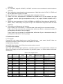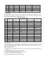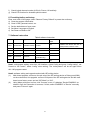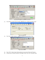
1
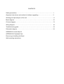
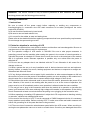
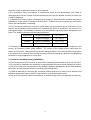
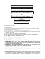
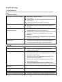
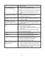
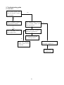
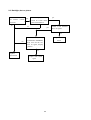
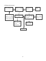
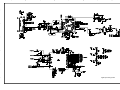
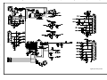
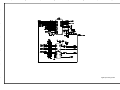
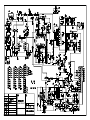
LCD-37XR8DA
1 682 345 69: CCIR DVB-T
SM0915045
CONTENTS
Safety precautions………………………………………………………………………..… 1
Alignment instructions and method of software upgrading………………………………3
Working principle analysis of the unit……………………………….………….………….11
Block diagram…………………………………..………………………………….…………12
IC block diagram………………………………………………………………………..……13
Wiring diagram ……………………………………………………………………………. 18
Troubleshooting guide ………………………………………………………………..…… 19
Schematic diagram………………………………………………………………………… 24
APPENDIX-A: Assembly list
APPENDIX-B: Exploded View
Removing or Installing the Stand
Wall mounting instructions
Attention: This service manual is only for service personnel to take reference with. Before
servicing please read the following points carefully.
Safety precautions
1. Instructions
Be sure to switch off the power supply before replacing or welding any components or
inserting/plugging in connection wire Anti static measures to be taken (throughout the entire
production process!):
a) Do not touch here and there by hand at will;
b) Be sure to use anti static electric iron;
c) It’s a must for the welder to wear anti static gloves.
Please refer to the detailed list before replacing components that have special safety requirements.
Do not change the specs and type at will.
2. Points for attention in servicing of LCD
2.1 Screens are different from one model to another and therefore not interchangeable. Be sure to
use the screen of the original model for replacement.
2.2 The operation voltage of LCD screen is 700-825V. Be sure to take proper measures in
protecting yourself and the machine when testing the system in the course of normal operation or
right after the power is switched off. Please do not touch the circuit or the metal part of the module
that is in operation mode. Relevant operation is possible only one minute after the power is
switched off.
2.3 Do not use any adapter that is not identical with the TV set. Otherwise it will cause fire or
damage to the set.
2.4 Never operate the set or do any installation work in bad environment such as wet bathroom,
laundry, kitchen, or nearby fire source, heating equipment and devices or exposure to sunlight etc.
Otherwise bad effect will result.
2.5 If any foreign substance such as water, liquid, metal slices or other matters happens to fall into
the module, be sure to cut the power off immediately and do not move anything on the module lest it
should cause fire or electric shock due to contact with the high voltage or short circuit.
2.6 Should there be smoke, abnormal smell or sound from the module, please shut the power off at
once. Likewise, if the screen is not working after the power is on or in the course of operation, the
power must be cut off immediately and no more operation is allowed under the same condition.
2.7 Do not pull out or plug in the connection wire when the module is in operation or just after the
power is off because in this case relatively high voltage still remains in the capacitor of the driving
circuit. Please wait at least one minute before the pulling out or plugging in the connection wire.
2.8 When operating or installing LCD please don’t subject the LCD components to bending, twisting
or extrusion, collision lest mishap should result.
2.9 As most of the circuitry in LCD TV set is composed of CMOS integrated circuits, it’s necessary
to pay attention to anti statics. Before servicing LCD TV make sure to take anti static measure and
ensure full grounding for all the parts that have to be grounded.
2.10 There are lots of connection wires between parts behind the LCD screen. When servicing or
moving the set please take care not to touch or scratch them. Once they are damaged the screen
1
would be unable to work and no way to get it repaired.
If the connection wires, connections or components fixed by the thermotropic glue need to
disengage when service, please soak the thermotropic glue into the alcohol and then pull them out
in case of dagmage.
2.11 Special care must be taken in transporting or handling it. Exquisite shock vibration may lead to
breakage of screen glass or damage to driving circuit. Therefore it must be packed in a strong case
before the transportation or handling.
2.12 For the storage make sure to put it in a place where the environment can be controlled so as to
prevent the temperature and humidity from exceeding the limits as specified in the manual. For
prolonged storage, it is necessary to house it in an anti-moisture bag and put them altogether in one
place. The ambient conditions are tabulated as follows:
Temperature
Humidity
Scope for operation
0 ~ +50 oC
Scope for storage
-20 ~ +60 oC
Scope for operation
20% ~ 85%
Scope for storage
10% ~ 90%
2.13 Display of a fixed picture for a long time may result in appearance of picture residue on the
screen, as commonly called “ghost shadow”. The extent of the residual picture varies with the
maker of LCD screen. This phenomenon doesn’t represent failure. This “ghost shadow” may remain
in the picture for a period of time (several minutes). But when operating it please avoid displaying
still picture in high brightness for a long time.
3. Points for attention during installation
3.1 The front panel of LCD screen is of glass. When installing it please make sure to put it in place.
3.2 For service or installation it’s necessary to use specified screw lest it should damage the screen.
3.3 Be sure to take anti dust measures. Any foreign substance that happens to fall down between
the screen and the glass will affect the receiving and viewing effect
3.4 When dismantling or mounting the protective partition plate that is used for anti vibration and
insulation please take care to keep it in intactness so as to avoid hidden trouble.
3.5 Be sure to protect the cabinet from damage or scratch during service, dismantling or mounting.
2
Alignment instructions
1. Test equipment
VG-848 (YPbPr,VGA signal generator)
VG-849 (HDMI signal generator)
CA210 (white balancer)
2. Power test
Connect data processing board, power board and IR board according the wiring diagram, connect
the power and press “standby” button to turn on the TV.
a) Test the pin voltage of X802, the data is shown in table1:
Table1 voltage data of X802
X802
Pin1
2
3
4
5, 6
7, 8
9
10
11
Voltage
8.55~9.45V
0
4.85~5.35V
0
11.4~12.6V
0
4.85~5.35V
0
>2.5
b) Test the pin voltage of XV01, the data is shown in table2:
Table2 voltage data of XV01
XV01
Pin1, 2
3, 4, 5
Voltage
23.8~25.2V
0
c) Test the pin voltage of X101, the data is shown in table3:
Table3 voltage data of X101
X101
Pin1
2
Voltage
31.4~32.6V
0
3. Alignment flow-chart
The alignment flow-chart is shown as fig-1
Check if DDC, HDCP KEY, FLASH are written
Combined test for general assembly
White balance adjustment
Connect to the center signal source and check each
function of TV (station leaking, analog control, etc.)
check the output of earphone and speaker.
3
Input AV/SVIDEO/SCART signal and check the function
Input HD signal and check the function of YPbPr
Input VGA signal and check if the display is normal, check
the function (analog control), horizontal/vertical center, etc.
Input HDMI signal and check if the display is normal, check
the function (analog control), horizontal/vertical center, etc.
Preset ex-factory
Check the accessories and packing
Fig-1 adjustment flow-chart
4. Adjustment instruction
4.1 Unit adjustments
4.1.1Connect all the boards according to wiring diagram, then power on and observe the display.
4.1.2 Method for entering factory menu:
a) Press “SOURCE”, “2”, “5”, ”8” and “0” in turn to enter factory menu;
b) Press “CH+” and “CH-” to move the cursor to the adjustment page of the level one factory menu,
then press ”OK” to enter;
c) Press “CH+” and “CH-” to move the cursor up and down;
d) Press “VOL-” and “VOL+” to adjust the item when the cursor move to a certain adjust item;
e) Press “MENU” to exit to the previous factory menu;
f) Press “EXIT” to exit the factory menu at any situation;
g) Press “OK” to enter the sub factory menu;
h) ADC ADJUST, ADC correction of VGA, Component channel;
i) W/B ADJUST, white balance adjustment;
j) POWER Mode, set the turn-on modes. Standby---standby when power on; Mem---memory;
ForceOn---power on; ForceOn can be used for aging; set the “power mode” to “Standby” when
preset ex-factory unless the client appointed it;
k) ISP Mode, ON---soft upgrading through VGA port with ISP device, OFF---DDC function of VGA;
the setting will not be memory and will be “OFF” when power on again;
l) REST ALL, initialization of the factory and user data; after this item is confirm, the unit will
restart and display the guiding image.
m) Factory Data Reset, factory data initialization (including white balance adjustment, ADC
correction and other adjusted data);
n) Factory Channel Preset, preset the factory channel; please connect to the center signal source
when operating; the present digital frequency is CH28 (529.5MHz), CH33 (564.5MHz) for
Australia and CH45 (666MHz) for UK, if the signal changes, perform “DTV manual search” in
4
“Channel” menu and the operation needs 15s or so.
o) MST Debug, the default is OFF. OFF---RS-232 should match the design criterion; ON--- it
should be convenient for using exploitation tool to adjust. The setting will not be memory and will
be “OFF” when power on again;
p) Backlight: adjust the backlight brightness, adjust the data and test the voltage of X804 pin2
(PWM), let the voltage to be the corresponding PWM voltage which the brightness is maximum.
It will be preset and doesn’t need adjust.
q) SSC Adjust, adjust the frequency spectrum expand, it will be preset and doesn’t need adjust.
r) AUDIO Curve, adjust the sound curve, it will be preset and doesn’t need adjust.
s) Picture Mode, set the picture values of each channel. Normally, they are preset and needn’t
adjust.
t) There is data in EEPROM after software upgrade, please perform Reset All before the first
adjustment.
4.2 ADC correction
4.2.1ADC correction in VGA channel
a) Switch to VGA channel.
b) Press” SOURCE”, then press “2, 5, 8, 0” in turn to enter the level one factory menu.
c) Move the cursor to “ADC ADJUST” and press OK to enter the sub-menu.
d) Input VGA signal (VG-848 Timing:856(1024x768/60Hz), Pattern:920 Gray 8 step(H)). Move the
cursor to “mode”, press CH+ and CH- to select “RGB”, move the cursor to “AUTO ADC” and
press OK to adjust automatically till complete.
4.2.2 ADC correction in YPbPr channel
a) Switch to YPbPr channel.
b) Press” SOURCE”, then press “2, 5, 8, 0” in turn to enter the level one factory menu.
c) Move the cursor to “ADC ADJUST” and press OK to enter the sub-menu.
d) Input YPbPr signal (VG-848 Timing:978(483P), Pattern:984 SMPTE Color Bar). Move the
cursor to “mode”, press CH+ and CH- to select “YPbPr(HD)”, move the cursor to “AUTO ADC”
and press ENTER to adjust automatically till complete.
e) Input YPbPr signal (VG-848 Timing:978(483P), Pattern:984 SMPTE Color Bar). Move the
cursor to “mode”, press CH+ and CH- to select “YPbPr(SD)”, move the cursor to “AUTO ADC”
and press ENTER to adjust automatically till complete.
4.3 White balance adjustment
The default of color temperature of COOL is 12000K and the coordinate is (272, 278); color
temperature of NORMAL is 9300K and the coordinate is (285,293), color temperature of WARM is
6500K and the coordinate is (313,329).
4.3.1 Adjustment steps
Before the white balance adjustment, please let the unit working at least 30 minutes and at a
stable situation, use BBY channel of the white balancer CA-210.
a) Switch to HDMI channel;
b) Press” SOURCE”, then press “2, 5, 8, 0” in turn to enter the level one factory menu.
c) Move the cursor to “W/B ADJUST” and press OK to enter the sub-menu.
d) Input DVI/HDMI signal 1024X768/60Hz 16 step Gray (Timing:856, Pattern:921). Move the
cursor to “MODE”, press CH+ and CH- to select “HDMI” or other HDMI channel, move the
cursor to “TEMPERTURE” and press CH+ and CH- to select “COOL”.
e) Fix G GAIN, adjust R GAIN, B GAIN and let the color coordinate of the fourteenth scale be
5
(272,278).
f) Fix G OFFSET, adjust R OFFSET, B OFFSET and let the color coordinate of the third scale be
(272,278).
g) When adjusting, please keep the color temperature of high light to be X=272±5, Y=278±5 and
the low light to be X=272±8, Y=278±8.
h) Move the cursor to “COPY ALL” and copy the data to the other channels.
i) Check if the color temperatures of NORMAL and WARM are up to the mustard (low light
acceptable error:±8, high light acceptable error:±5), if not, adjust R-GAIN/ B-GAIN/ R-OFF/
B-OFF.
j) Check the color temperature of COOL, NORMAL and WARM of other channels (ANALOGTV,
DVB-T, Video, YPbPr,VGA), if they are not up to the mustard then adjust and store the data
separately.
k) The reference of adjustment rule is below:
B gun: lower B gun to increase X, Y coordinate data, while raise B gun to decrease the data.
R gun: raise R gun to increase X coordinate data, while lower R gun to decrease the data; (R
gun adjustment will affect X and Lv slightly).
G gun: raise G gun to increase Y coordinate data, while lower G gun to decrease the data; (G
gun adjustment will affect Y and Lv greatly).
5. Performance check
5.1 TV function
Connect RF to the center signal source, enter Channel menu → auto search, check if there are
channels be skipped, check if the picture and speaker are normal.
5.2 AV/S-Video terminals
Input AV/S-Video signal, check if the picture and sound are normal.
5.3 YPbPr/YcbCr terminal
Input YUV signal (VG848 signal generator), separately input the YUV signals listed in table4 and
check if the display and sound are normal at any situation (power on, channel switch and format
convert, etc.)
Table4 YUV signal format
No.
Resolution
H-frequecny
V-frequecny
Point clock pulse
(kHz)
(kHz)
frequecny (MHz)
Note
1
720X480
15.734
60
13.5
480i(NTSC)
2
720X480
15.734
59.94
13.5
480i(NTSC)
3
720X576
15.625
50
13.5
576i(PAL)
4
720X480
31.469
60
27
480p(NTSC PROG)
5
720X480
31.469
59.94
27
480p(NTSC PROG)
6
720X576
31.25
50
27
576p(PAL PROG)
7
1280X720
45
59.94
74.18
720p(59p)
8
1280X720
45
60
74.25
720p(60p)
9
1280X720
37.5
50
74.25
720p(50p)
10
1920X1080
33.75
59.94
74.25
1080i(59i)
11
1920X1080
33.75
60
74.25
1080i(60i)
12
1920X1080
28.125
50
74.25
1080i(50i)
6
13
1920X1080
67.5
59.94
148.35
1080p(59p)
14
1920X1080
67.5
60
148.5
1080p(60p)
15
1920X1080
56.25
50
148.5
1080p(50p)
16
1920X1080
-
23.94/24
-
-
17
1920X1080
-
25
-
-
18
1920X1080
-
29.97/30
-
-
5.4 VGA terminal
Input VGA signal (VG848 signal generator), separately input the signals listed in table5 and check
the display and sound. If the image is deflection of the Horizontal and vertical, select
Picture->Screen->Auto Adjusting to perform auto-correct.
Table5 VGA signal format
No.
H-frequecny
Resolution
(kHz)
Point clock pulse
V-frequecny (kHz)
Note
frequecny (MHz)
1
640X480
31.469
59.94
25.175
IBM
2
720X400
31.469
70.086
28.322
IBM
3
640X480
37.861
72.809
31.5
VESA
4
640X480
37.5
75
31.5
VESA
5
800X600
35.156
56.25
36
VESA
6
800X600
37.879
60.317
40
VESA
7
800X600
48.077
72.188
50
VESA
8
800X600
46.875
75
49.5
VESA
9
1024X768
48.363
60.004
65
VESA
10
1024X768
56.476
70.069
75
VESA
11
1024X768
60.023
75.029
78.75
VESA
12
1152X864
67.5
75
108
VESA
13
1280X960
60
60
108
VESA
14
1280X1024
63.98
60.02
108
VESA
15
1280X1024
80
75
135
SXGA
16
1440X900
-
60
-
-
17
1680X1050
-
60
-
-
18
1360X768
47.7
60
85.5
-
5.5 HDMI terminal
Input HDMI signal (VG849 signal generator), separately input the signals listed in table4 and table5
and check the display and sound (32KHz, 44.1KHz, 48KHz) at any situation (power on, channel
switch and format convert, etc.)
5.6 other functions check
a) Check the turn on/turn off timer, sleep timer, picture/sound mode, OSD, stereo and digital sound
port, etc.
b) Check the digital program, if Audio Only is normal.
c) Check MHEG function of the digital program for UK unit.
d) Check if “CI: Common Interface” is normal.
e) Check logical channel number (LCN) for Australia.
7
f) Check logical channel number (LCN) for France, UK and Italy.
g) Check OTA function for Australia special custom.
6. Presetting before ex-factory
Enter user menu LOCK page, select “Restore Factory Default” to preset the ex-factory.
a) Clear the program information.
b) Clear VCHIP, parental control, etc.
c) Set the default data of user menu.
d) Set Menu Language to English.
e) Set Power on Mode to Off.
7. Software instruction
Table6 software instruction
No.
Code No.
Type
Function
written before
Method
paste
Yes
N810
5272532003
EN25B32-100HIP
FLASH
N807
5272404002
AT24C04
HDMI KEY
Yes
NA03
5272402002
AT24C02
HDMI EDID
Yes
NA04
5272402002
AT24C02
HDMI EDID
NA08
5272402002
AT24C02
N107
5272421002
AT24LC21A
HDMI
Written with device like ALL11,
write-protect, refer to note1.
Written with device like ALL11
Yes
EDID
Yes
(Australia only)
Yes
VGA EDID
Note1: write-protect setting: enter ALL-100 interface, select Config and press “config setting”, set
Protect to “All Protect”, select “config” when writing. The “write-protect” will be set again when
ALL-100 program restart.
Note2: software writing and upgrade method with ISP writing-device
(1)
Main board upgrade: connect a four-pin wire of the ISP writing-device to Debug port(X806)
on the main board; Unit upgrade: connect VGA ports of the ISP writing-device and the main
board, enter factory menu and set “ISP Mode” to “ON”.
(2)
Using Mstar writing-tool on line, click “Connect” menu, if it displays “Device EN25B32“ as
shown in fig2, the connection is success, if it fails, select “EN25B52” of “Device” manually
and press “Connect” again.
8
Fig2 Device EN25B52 successful connection
(3)
Click “Read” and select the file written (MERGE.bin for example) as shown in fig3.
(4)
Fig3 the written file
Click “Auto”, select “All chip” , “program” and other items as shown if fig4.
Fig4 selected items
(5)
(6)
Press “Run” in fig4 to begin writing and there are two steps: Erase and Program.
If the process of writing succeeds, it will display “Pass” near “Run” as shown in fig5.
9
(7)
Fig5
Repeat step 2) and 5) to write the program to the other units without exit the ISP interface.
Note3: software writing and upgrade method with USB port
(1)
Make sure the USB device is formatted as FAT32.
(2)
Copy the program named Merge.bin to USB device.
(3)
Insert the USB device to USB port of the unit, power on and select RF-ATV channel, begin
USB upgrade after OSD disappear. It will display blue when read the data from USB device,
while display red when write Flash. The flash must be pull out when display red. It will flicker
in red and blue if the process of writing is abnormal.
(4)
The method are not applicable to all the USB devices, try another one if a certain USB device
is inapplicable.
10
Working principle analysis of the unit
1. PAL/SECAM signal flow:
Antenna reception PAL/SECAM signal will be send to tuner TDA1616, which contains frequency
turning, HF and IF amplifier circuit and is controlled by master control IC MSD109 (comprises CPU)
through I2C bus. The analog IF signal via intermediate frequency amplifying, video SAW filter
K3953 and audio SAW filter K9656 to input to analog demodulate IC (IF) R2A10406NP, after
demodulating and output standard video signal TV-CVBS and sound IF signal (SIF).
TV-CVBS will send to the master control IC MSD109 to video decode, deinterlace and scale, then
output LVDS level drive for panel display.
The sound IF (SIF) will be fed into MSD109, after demodulating, pre-amplifying, bass adjusting and
volume control, the sound signal will separate into L/R channels and input to earphone amplifier
BH3547F amplifying, then output two ways. One way will be sent to earphone, another will be sent
to digital sound amplifier R2A15112FP amplifying then sent to speaker.
2. DVB-T signal flow:
Antenna reception DVB-T signal will be sent to tuner TDA1616, after frequency tuning, HF
amplification, IF amplification and SAW FILTER, output IF signal to demodulation chip CE6353, via
QAM demodulation, fed to MSD109 for information source decoding in the format of standard serial
TS stream.
HD video signal via decoding to A/D conversion and OSD superposition, at last output LVDS drive
level for panel display.
HD audio signal via decoder built-in MSD109, resumed to multi- channel sound of Dolby AC-3. The
audio signal will be sent to back end to perform bass adjustment and volume control, then it will
separate into L/R channels and input to earphone amplifier BH3547F amplifying, then output two
ways. One way will be sent to earphone, another way will be sent to digital sound amplifier
R2A15112FP amplifying then sent to speaker.
3. AV/SV signal flow
SV signal and the first path AV signal switch automatically via S-terminal socket, the signal and the
second path AV signal will be fed to MSD109 to perform video decode, deinterlace and scale, then
output LVDS drive level for panel display.
Audio signal from AV/SV via matched resistance is fed to external audio switch HEF4052 to switch,
then it is directly sent to MSD109 to bass adjust and volume control, the sound will separate into L/R
channels and input to earphone amplifier BH3547F amplifying, then output two ways. One way will
be sent to earphone, another way will be sent to digital sound amplifier R2A15112FP amplifying
then sent to speaker.
4. PC/YPrPb signal flow
PC and the second path YPbPr signal are switched via external switcher PI5V330, then the signal
and the first path YPbPr signal will be sent to MSD109 A/D conversion, output R/G/B of 24 bit to
back end module to digital decode, image scale and OSD superposition, then send to LVDS level
drive for panel display.
Sound signal of PC/YPrPb via matched resistance and a-c couple are sent to MSD109 to bass
adjust and volume control, the sound will separate into L/R channels and input to earphone
11
amplifier BH3547F amplifying, then output two ways. One way will be sent to earphone, another
way will be sent to digital sound amplifier R2A15112FP amplifying then sent to speaker.
5. HDMI signal flow
Three HDMI video signals via switcher PS321 are directly fed to the master control IC MSD109 to
digital decode, image scale and OSD superposition, then output LVDS drive level for panel display.
HDMI audio signal via decoder built-in MSD109 is fed to back end to bass adjust and volume
control, the sound will separate into L/R channels and input to earphone amplifier BH3547F
amplifying, then output two ways. One way will be sent to earphone, another way will be sent to
digital sound amplifier R2A15112FP amplifying then sent to speaker.
Block diagram
12
IC block diagram
1. MSD109CL
Twin-turbo 8051 MCU
Supports multi-path TS stream input
Two paths TS stream output, integrated switch selection
Supports both serial and parallel TS stream input
Maximum TS data rate is 104Mbps for serial or 13MB/sec for parallel
MPEG-2 audio decoder
MPEG-1, MPEG-2 (Layer I/II) and Dolby1 Digital(AC-3) audio decoder
MPEG-4 decoder
NTSC/PAL/SECAM video decoder
Supports NTSC-M, NTSC-J, NTSC-4.43, PAL (B,D,G,H,M,N,I,), and SECAM
Multi-standard sound processor
Supports BTSC/A2/EIA-J demodulation in NTSC and A2/NICAM/FM/AM demodulation in PAL
Supports MTS Mode MONO/STEREO/SAP in BTSC/EIA-J and MONO/STEREO/DUAL in
A2/NICAM
Digital Audio Interface
Analog RGB Compliant/YUV input Ports
Two analog ports support up to 1080P
Supports PC RGB input up to SXGA@75Hz
Supports HDTV RGB/YPbPr/YCbCr
Supports Composite Sync and SOG (Sync-on-Green) separator
Automatic color calibration
DVI/HDCP/HDMI input ports
Supports up to 225MHz @ 1080P 60Hz with 12-bit deep-color resolution
High-bandwidth Digital Content Protection (HDCP) 1.1 compliant receiver
High Definition Multimedia Interface (HDMI) 1.3 compliant receiver with CEC (Consumer
Electronics Control) support
Video Processing & Conversion
3-D motion adaptive video de-interlacers with edge-oriented adaptive algorithm for smooth
low-angle edges
Automatic 3:2 pull-down & 2:2 pull-down detection and recovery
10-bit internal data processing
3-D video noise reduction
Output Interface
Supports up to 10-bit dual LVDS full-HD (1920 x 1080) panel interface
Video output port
Supports CVBS/S-video bypass output
Built-in video encoder for encoding digital video into CVBS output
Miscellaneous
Supports DVB-CI port conditional receiver
USB 2.0 port can be connected to the external equipment for software upgrading
13
2. CE6353
The chip comprises 8MHz bandwidth SAW and supports demodulation of 6MHz, 7MHz and 8MHz,
2K/8K carrier and supports both serial and parallel TS stream output.
3. R2A10406NP
*VIF frequency corresponds to 38.9MHz.
*SIF frequency corresponds to M/N,B/G,I,D/K and SECAM L,L'.
*I2CBUS control.
14
4. PS321
The chip supports both I2C control and I/O control mode; supports both internal and external EDIT.
5. R2A15112FP
15
6. TDA1616
16
17
Wiring diagram
panel
back
light
board
data board
IR/key board
power board
adjustment port
speaker
power switch
18
Trouble shooting
1. Fault clearance
Before servicing please check to find the possible causes of the troubles according to the table
below.
1.1 Antenna (signal):
Picture is out of focus or jumping
Bad status in signal receiving
Poor signal
Check if there are failures with the electrical connector or
the antenna.
Check if the antenna is properly connected.
Fringe in picture
Check if the antenna is correctly oriented.
Maybe there is electric wave reflected from hilltop or
building.
Picture is interfered by stripe
Possibly due to interference from automobile, train, high
shaped bright spots
voltage transmission line, neon lamp etc.
Maybe there is interference between antenna and power
supply line. Please try to separate them in a longer
distance.
Maybe the shielded-layer of signal wire is not connected
properly to the connector.
There appear streaks or light color
Check if interfered by other equipment and if interfered
on the screen
possibly by the equipment like transmitting antenna,
non-professional radio station and cellular phone.
1.2 TV set:
Symptoms
Unable to switch the power on
No picture and sound
Deterioration of color phase or
color tone
Screen position or size is not
proper
Picture is twisted and deformed
Picture color changed or colorless
Possible cause
Check to see if the power plug has been inserted
properly into the socket.
Check to see if the power supply of liquid crystal TV has
been switched on. (As can be indicated by the red LED
at the front of the TV set)
See if it’s receiving the signal that is transmitted from
other source than the station
Check if it’s connected to the wrong terminal or if the
input mode is correct.
Check if the signal cable connection between video
frequency source and the liquid crystal TV set is correct.
Check if all the picture setups have been corrected.
Check is the screen position and size is correctly set up.
Check to see if the picture-frame ratio is properly set up.
Check the “Component” or “RGB” settings of the liquid
19
Picture too bright and there is
distortion in the brightest area
Picture is whitish or too bright in
the darkest area of the picture
No picture or signal produced from
the displayer if “XXX in search”
appears.
There appears an indication “outside the receivable scope)
Remote control cannot work
properly
No picture and sound, but only
hash.
Blur picture
No sound
When playing VHS picture search
tape, there are lines at the top or
bottom of the picture.
crystal TV set and make proper adjustment according to
the signal types.
Check if the contrast setting is too high.
Possibly the output quality of DVD broadcaster is set too
high.
It maybe also due to improper terminal connection of the
video frequency signal in a certain position of the
system.
Check if the setting for the brightness is too high
Possibly the brightness grade of DVD player
(broadcaster) is set too high.
Check if the cable is disconnected.
Check if it’s connected to the proper terminal or if the
input mode is correct.
Check if the TV set can receive input signal. The signal is
not correctly identified and VGA format is beyond the
specified scope.
Check if the batteries are installed in the reverse order.
Check if the battery is effective.
Check the distance or angle from the monitor.
Check if there is any obstruct between the remote control
and the TV set.
Check if the remote control signal- receiving window is
exposed to strong fluorescence.
Check if the antenna cable is correctly connected, or if it
has received the video signal correctly.
Check if the antenna cable is correctly connected.
Of if it has received the right video signal.
Check if the “mute” audio frequency setting is selected.
Check if the sound volume is set to minimum.
Make sure the earphone is not connected.
Check if the cable connection is loose.
When being played or in pause VHS picture search tape
sometimes can’t provide stable picture, which may lead
to incorrect display of the liquid crystal TV, In this case
please press “auto” key on the remote control so as to
enable the liquid crystal TV set to recheck the signal and
then to display correct picture signal
20
2. Troubleshooting guide
2.1. No raster
Turn-on power supply, check
if the red indicator is light in
the STANDBY?
yes
no
Check if 5VSTB of X802 9#
on main board is normal?
Press POWER button on the
unit or sensor control and
check the indicator.
red
blue
no
Check if the PIN3 of X804 on
main board is high-level?
Check STANDBY circuit of
power supply board
yes
no
Check power board and
back light board
Check if the PIN11 of X802 on
main board is high-level?
Check the backlight
control circuit on the
main board
yes
Check power
supply board
21
2.2. Backlight, but no picture
Check if the unit button
and remote control
operation?
no
yes
Does display OSD
menu on screen when
press menu button?
no
yes
yes
Check if all channels
have no signal?
no
no
Enter
factory-menu,
initialization EEPROM,
then turn off the TV,
turn on again, display
picture?
Replace main
board
yes
Replace
main board
Adjust main board
again
22
2.3 Picture, but no sound
Check if NV02 pin4,
5, 32, 33 are 24V?
no
Check 24V power
supply of power
board and the path
between XV03 and
NV02 on main board
yes
Check if NV02
pin10, 27 are high
voltage?
yes
no
Is there sound in
earphone?
yes
Replace
NV02
no
If NS01 pin126, 148
are low voltage?
Is there sound when
touch CV04, CV05
with probe?
no
Check the path
between NS01 pin
126,148
and
NV02 pin10, 27
Check earphone
amplify circuit
Replace NS01
23
yes
Check
the
audio output
circuit of the
main IC
digital processing board
digital processing board
digital processing board
digital processing board
digital processing board
digital processing board
digital processing board
digital processing board
Power board
IR $ Key
APPENDIX-A: Main assembly (LCD-37XR8DA)
Name Digital processing board No. XI6HE0296910 IR board Keyboard Power board Remote control Panel XI6HC0030910 XI6HK0260510 XI6HU0282010 XI6010J01701 XI5203375302 Main components and its No. NS01 MSD109CL (5270109001) N101 R2A10406NP (5271040601) CE6353 (5276353001) NJ01 NA05 PS321TQF (5270321001) NV02 R2A15112FP (5271511201) RC‐J17‐0A T370XW02 V508 APPENDIX-B: Exploded view (LCD-37XR8DA)
10
9
8
Part list
2
3
4
1
No.
Description
1
Front cabinet
2
Power switch
3
Speaker
4
Panel
5
Power board
6
Back cabinet
7
Stand
8
Digital processing board
9
Keyboard
10
IR board
5
6
7
Mechanical Replacement Parts List (LCD-37XR8DA ver. 1.0)
Ref. No.
1
2
3
4
5
6
7
8
9
10
11
12
Part No.
XI5QY37L0050
XI5293000042
XI5501006015
XI5203375302
XI6HU0282010
XI5HY37LK010
XI6151157010
XI6HE0296910
XI6HK0260510
XI6HC0030910
XI5944033570
XI6010J01701
Description
Front cabinet
Power Switch
Speaker
Panel
Power board
Back cabinet
Stand
Digital processing board
Keyboard
IR Board
User manual
Remote control
Q’TY
1
1
2
1
1
1
1
1
1
1
1
Note:
•
•
Only the parts in above list are used for repairing.
Other parts except the above parts can’t be supplied.
Remarks
T370XW02 V508
RC-J17-0A
Removing or Installing the Stand
Cautions:
1. Carefully handle the unit during setup and consult authorized service personnel to ensure successful
installation.
2. Before performing work spread cushioning over the base area to lay the Display on. This will prevent it from
being damaged.
3. Disconnect the AC power cord firstly.
To remove the stand: (if wall mounting)
1.Lay your TV flat (screen down) on a table or bench. Make sure that you put down a soft cushion or cloth so that your TV
is not scratched.
2.Loosen the five M4 screws on the Stand to remove the Stand. (Please keep these screws for future use if you want
to install the stand again.)
Remove five screws
To install the stand
1.Lay your TV flat (screen down) on a table or bench. Make sure that you put down a soft cushion or cloth so that your TV
is not scratched.
2. Align the locator holes in the stand with the locators on the TV back, and then align the holes in the stand column with the
holes in the TV back, and then secure the stand to the TV with five M4 screws.
Locator
Locator hole
Stand
Use five M4 screws to
secure the stand to the TV
3.Place your TV upright.
Note
! Do not remove the stand from the TV unless using an optional bracket to mount it.
! The appearance of the unit may differ from the actual one.
WALL MOUNTING INSTRUCTIONS
27
Safety Precautions:
1. Be sure to ask an authorized service personnel to carry out setup.
2. Thoroughly read this instruction before setup and follow the steps below precisely.
3.The wall to be mounted should be made from solid materials. Only use accessories supplied by the manufacturer.
4.Very carefully handle the unit during setup. We are not liable for any damage or injury caused by mishandling or improper installation.
5.Be sure to place the unit on a stable and soft platform which is strong enough to support the unit.
6.Do not uplift the speaker when moving the display. The appearance of the unit may different from the actual ones.
7.Design and specifications are subject to change without notice.
8. Retain these instructions for future reference.
X
Below we will show you how to mount the
Display on the wall using our company’s
wall mounting components.
Wall
Wall
8
Wall Mounting Holder
Wall Mounting Connector
200
Take out these
parts from the
box
(Unit:mm)
Note: All the wall mounting parts are
optional and may be unavailable in
your model.
Expansion Bolt
Wood Screw
Combination Screw
Wall mounting fix-hole center
Fig.1
1. There are three options of wall mounting
holder with different
specifications
:200200,200400,200600. Please check your
wall mounting holder for its specification.
Rear wall mounting hole center
Fig.2
2. Due to the wall mounting fix-groove leaning to the
right side, the whole unit will lean to right side after
installation, please carefully measure the position of
the holes you want to drill, refer to the parameters
on Fig.2 when drilling the holes.
Fig.3a
Fig.3b
3a. Screw 4pcs expansion bolts to fix the
wall mounting holder on the wall.
3b. If your wall is a wooden structure, please
fix the wall mounting holder on the wall
with 16pcs wood screws.
Note: The "X" in Fig.2 represents a data. It may be
200mm or 400mm or 600mm.
Fig.7
Fig.6
Fig.4
4. Use the 4pcs combination screws to fix
the wall mounting connector to the rear
of the display unit.(Caution:the direction
of the connectors should be strictly
confirm to the diagram illustrated above).
Fig.5
5. Put the back of the display unit close to the wall
mounting holder, insert the four wall mounting
connectors into the four calabash-shaped holes on
the wall mounting holder. (Fig.5)
6. Let the display unit slowly slide down to
the end of the calabash-shaped hole.
(Fig.6)
7. Push rightwards carefully until the wall
mounting connectors fully slide into the
right fix-grooves and be sure the mounting
is secure.
8. If you want to dismount the unit do the above steps in reverse order.
SEP/2008