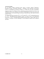
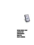
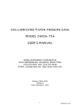
1
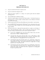
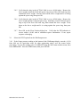
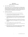
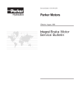
AUTOFLOAT SYSTEM MODEL 2465A USER'S MANUAL RUSKA INSTRUMENT CORPORATION 10311 WESTPARK DRIVE, HOUSTON, TX 77042 (713) 975-0547 FAX (713) 975-6338 e-mail: [email protected] Release: 2465A-1D00 Revision: B Date: 02/28/01 TABLE OF CONTENTS Table of Contents..........................................................................................................................-iiWarranty ..................................................................................................................................... -iiiCopyright Notice..........................................................................................................................-ivDisclaimer ....................................................................................................................................-ivTrademark Notice ........................................................................................................................-ivRevision Notice.............................................................................................................................-vRevision History ..........................................................................................................................-viWarning.......................................................................................................................................-viiOxygen Compatibility............................................................................................................... -viii- SECTION 1.0 SYSTEM DESCRIPTION 1.1 Overview...............................................................................................................-1- SECTION 2.0 SETUP 2.1 General..................................................................................................................-3- 2.2 Deadweight Gauge (DWG) Base..........................................................................-3- 2.3 Vacuum Pumps .....................................................................................................-4- 2.4 Pressure Controller Chassis and Computer...........................................................-4- SECTION 3.0 PREPARATION FOR USE....................................................... -5SECTION 4.0 BASIC OPERATING ROUTINE 4.1 Activate Calibration Routine ................................................................................-7- 4.2 Generating Pressures.............................................................................................-7- 4.3 System Shutdown..................................................................................................-8- SECTION 5.0 CALIBRATION .......................................................................................-9- INTRODUCTION -ii- WARRANTY Ruska Instrument Corporation warrants its products to conform to or exceed the specifications as set forth in its catalogs in use at the time of sale and reserves the right, at its own discretion, without notice and without making similar changes in articles previously manufactured, to make changes in materials, designs, finish, or specifications. Ruska Instrument Corporation warrants products of its own factory against defects of material or workmanship for a period of one year form date of shipment. Liability of Ruska Instrument Corporation under this warranty shall be limited to replacing, free of charge (FOB Houston, Texas), any such parts proving defective within the period of this warranty, but will not be responsible for transportation charges or consequential damages. This warranty is not made for products manufactured by others which are illustrated and described in Ruska catalogs or incorporated in Ruska products in essentially the same form as supplied by the original manufacturer. However, Ruska Instrument corporation agrees to use its best efforts to have original suppliers make good their warranties. -iii- INTRODUCTION COPYRIGHT NOTICE Copyright 1990, 1991, 1992 by Ruska Instrument Corporation. All rights reserved. This document may not be reproduced in part or in whole without the express written consent of Ruska Instrument Corporation. DISCLAIMER No representations or warranties are made with respect to the contents of this user's manual. Further, Ruska Instrument corporation reserves the right to revise this manual and to make changes from time to time in the content hereof without obligation to notify any person of such revision. TRADEMARK NOTICE RUSKA is a trademark of Ruska Instrument Corporation. Trademarks or tradenames are subject to state and federal laws concerning their unauthorized use or other infringements. The fact that the product marks or names in this manual do not bear a trademark symbol DOES NOT mean that the product name or mark is not registered as a trademark or tradename. Any queries concerning the ownership or existence of any trademarks or tradenames mentioned in this manual should be independently confirmed with the manufacturer or distributor of the product. INTRODUCTION -iv- REVISION NOTICE RELEASE NUMBER REVISION DATE OF REVISION DESCRIPTION 2465A-1D00 A 02/19/99 Original release for 2465A-System 2465A-1D00 B 02/29/01 Added Section 5.0. -v- INTRODUCTION REVISION HISTORY INTRODUCTION -vi- WARNING PRESSURIZED VESSELS AND ASSOCIATED EQUIPMENT ARE POTENTIALLY DANGEROUS. THE APPARATUS DESCRIBED IN THIS MANUAL SHOULD BE OPERATED ONLY BY PERSONNEL TRAINED IN PROCEDURES THAT WILL ASSURE SAFETY TO THEMSELVES, TO OTHERS, AND TO THE EQUIPMENT. DO NOT USE OXYGEN AS THE PRESSURE SUPPLY MEDIA. USE ONLY DRY, CLEAN NITROGEN. DO NOT EXCEED SAFE MAXIMUM INLET PRESSURES AS FOLLOWS: WITH LOW RANGE PISTON/CYLINDER: 40 PSIA (POUNDS PER SQUARE INCH ABSOLUTE) WITH MID RANGE PISTON/CYLINDER: 115 PSIA WITH HIGH RANGE PISTON/CYLINDER: 1015 PSIA DO NOT USE HYDRACARBON LUBRICANTS. USE ONLY RUSKA INSTRUMENT CORPORATION SUPPLIED LUBRICANT, PART NUMBER 45-339, UNLESS OTHERWISE SPECIFIED IN THIS MANUAL. ALWAYS USE REPLACEMENT PARTS SPECIFIED BY RUSKA INSTRUMENT CORPORAITON. WHEN ANY MAINTENANCE IS PERFORMED, TURN OFF POWER AND REMOVE POWER CORD. -vii- INTRODUCTION OXYGEN COMPATIBILITY This instrument has been designed with components that will not introduce hydrocarbons into the calibration process. The O-ring and lubricating grease supplied with the instrument must not be substituted with other laboratory supplies. Cleaning of the instrument for oxygen compatibility using liquid Freon and ultrasonic cleaning systems is permitted with the EXCEPTION OF THE PISTONS AND CYLINDERS. The Ruska procedures for piston/cylinder cleaning as described in Section 6.0 of this manual must be followed. ULTRASONIC CLEANING MAY DAMAGE THE CRYSTALLINE STRUCTURE OF THE TUNGSTEN CARBIDE PISTONS AND CYLINDERS. INTRODUCTION -viii- SECTION 1.0 SYSTEM DESCRIPTION The Ruska Model 2465A AutoFloat System combines the high precision and low uncertainty of the Ruska Model 2465 Pneumatic Piston Pressure Gauge with the ease-of-use of the Ruska Model2465A-200 AutoFloat Controller and WinPrompt 32 software. All pressure generation functions, mass load computations and data collection are performed via Ruska WinPrompt Calibration Software to provide consistency and efficiency in the calibration routine. 1.1 OVERVIEW The user activates the desired calibration routine through the WinPrompt 32 software. At the direction of WinPrompt, the user installs the appropriate piston/cylinder assembly and loads the requested masses. For absolute mode operation, the user must also install the bell jar and operate the vacuum valve, as prompted by WinPrompt. WinPrompt then commands the pressure controller to pressurize the system and establish the proper piston float and rotation, during which time the status bar display in WinPrompt is red. The vacuum pumps will also be activated by WinPrompt as needed. Once proper piston float and rotation have been established, WinPrompt changes the status bar from red to yellow to green. As the piston position drifts out of optimum float range, the status bar changes to yellow, and then to red as the pressure controller activates to reestablish the optimum float position. After sufficient stabilization time, the user enters the reading from the device under test and WinPrompt proceeds with instrument sfor the next pressure in the sequence. This continues until all pressures in the sequence have been generated. The user can then print a Default Calibration Report or activate a third-party program that supports Dynamic Data Exchange (DDE) and print a Customer Calibration Report that includes links to actual WinPrompt data. Although the Model 2465A AutoFloat System is designed to minimize the burden on the user, it remains the user's responsibility to use good metrological practices. These include allowing adequate time for thermal stabilization, ensuring leak integrity of the pressure system, ensuring adequacy of the environmental controls, and acquiring a reliable value for the local acceleration of gravity. -1- SYSTEM DESCRIPTION THIS PAGE INTENTIONALLY LEFT BLANK SYSTEM DESCRIPTION -2- SECTION 2.0 SETUP 2.1 GENERAL The Model 2465A AutoFloat System should be set up on a sturdy table in a location where the thermal fluctuations are at a minimum; as far as possible away from air conditioning vents, heaters and exterior windows. Drafts due to air handlers and personnel traffic are also undesirable. Use the following guide to make the connections between the various system components and to prepare the system for operation. 2.2 2465A-754 DEADWEIGHT GAUGE (DWG) BASE 2.2.1 Verify voltage selection on power receptacle and connect power cord. 2.2.2 Verify that the Rotation control switch on the rear of the DWG base is set to Automatic. 2.2.3 Connect the DWG base pressure port to the rear test port connection on the Pressure Controller chassis using a pressure line and fittings rated for 1000 psi. A flexible line rated to 1000 psi is included in the optional lines and fittings kit supplied with some systems. 2.2.4 Install the Vacuum Sensor into the DWG base. 2.2.5 Connect the Vacuum Sensor Cable to the Vacuum Sensor and to the rear panel connector on the Pressure Controller chassis labeled Vacuum. 2.2.6 Connect a BNC cable between the DWG base and the rear panel connector on the Pressure Controller chassis labeled FLOAT. 2.2.7 Insert the PRT sensor into the DWG base and tighten the swage connector only enough to prevent the PRT from slipping out accidentally. Connect the cable to the rear panel connector on the Pressure Controller chassis labeled PRT. 2.2.8 Connect the 11-pin cable between the DWG base and the rear panel connector on the Pressure Controller chassis labeled Rotation. --3- SETUP 2.3 VACUUM PUMPS 2.3.1 Plug the power cable from the Supply Vacuum Pump (the lower capacity, smaller body pump) to the rear panel electrical outlet on the Pressure Controller chassis labeled SUPPLY VACUUM PUMP. 2.3.2 Connect the Supply Vacuum Pump vacuum port to the rear panel connector on the Pressure Controller chassis labeled SUPPLY VACUUM using 3/8 inch or larger tubing. Suitable tubing is included in the optional lines and fittings kit supplied with some systems. 2.3.3 Verify that the power switch on the Supply Vacuum Pump is set to ON. 2.3.4 Plug the power cable from the Reference Vacuum Pump (the higher capacity, larger body pump) to the rear panel electrical outlet on the Pressure controller chassis labeled REFERENCE VACUUM PUMP. 2.4 2.3.5 Connect the Reference vacuum Pump vacuum port to the bell jar evacuation port flange on the side of the DWG base. 2.3.6 Verify that the power switch on the Reference Vacuum Pump is set to ON. 2465A-200 PRESSURE CONTROLLER CHASSIS AND COMPUTER 2.4.1 Connect a regulated pressure supply to the rear connection on the Pressure controller chassis labeled SUPPLY PRESSURE using a pressure line and fittings rated for operation at 1000 psi. Copper tubing and fittings rated for this application are included in the optional lines and fittings kit supplied with some systems. 2.4.2 Connect the Device Under Test pressure port to the rear Test Port connection on the Pressure controller chassis using a pressure line and fittings rated for operation at 1000 psi. A flexible line rated to 1000 psi is included in the operational lines and fittings kit supplied with some systems. 2.4.3 Connect communication cable between the computer and the rear panel connector on the Pressure Controller chassis labeled RS232. 2.4.4 SETUP Connect power cord from rear of Pressure Controller chassis to 120 or 230 VAC (nominal) supply, as applicable. -4- SECTION 3.0 PREPARATION FOR USE 3.1 Set power switch on the Pressure Controller to ON. 3.2 Set power switch on the computer to ON. 3.3 Adjust the pressure regulator to a setting a few percent greater than the intended operating pressure. 3.4 Activate WinPrompt 32 calibration software. 3.5 Switch the computer display to show the 2465 Status window. Verify that all sensors are indicating properly. This may include verification that the correct calibration coefficients are loaded for each sensor. 3.6 Install a piston into the DWG base and load both parts of mass number 1 onto the piston. 3.7 Select the PRESSURIZE option from the WinPrompt 32 menu, and pressurize the system to 1 psi if the low range is installed, 4 psi for the mid range piston, and 25 psi if the high range is installed. 3.8 Push down on the sleeve weight until the piston and sleeve weight are at the bottom of travel. If the FPI indication is within +/-0.005 of -0.200 inch, proceed to step 9. IF the FPI sensor reading is outside this limit, perform the FPI alignment as follows: 3.8.1 Activate the CALIBRATE item on the 24365 Status window menu, select FPI, then select the 5 POINT CALIBRATION button. 3.8.2 Verify that the value in the ACTUAL field is set to -0.200 inches (or other appropriate value if different engineering units are selected). Press down on the sleeve weight until it is resting against the lower stop, then press OK. 3.8.3 Verify that the value in the ACTUAL field is set to -0.100 inches. Remove the sleeve weight, install the 0.100 inch spacer ring around the pressure column and reinstall the sleeve weight. Press down on the sleeve weight until it is resting against the spacer ring, then press OK. 3.8.4 Verify that the value in the ACTUAL field is set to 0.000 inches. Remove the sleeve weight and the 0.100 inch spacer ring. Install the 0.200 inch spacer ring and the sleeve weight. Press down on the sleeve weight until it is resting against the spacer ring, then press OK. -5- PREPARATION FOR USE 3.9 3.8.5 Verify that the value in the ACTUAL field is set to +0.100 inches. Remove the sleeve weight, install the 0.100 inch spacer ring on top of the 0.200 inch ring, then reinstall the sleeve weight. Pressure down on the sleeve weight until it is resting against the spacer ring, then press OK. 3.8.6 Verify that the value in the ACTUAL field is set to +0.200 inches. Remove the sleeve weight and the 0.100 inch spacer ring. Install the second 0.200 inch spacer ring on top of the first 0.200 inch ring, then reinstall the sleeve weight. Press down on the sleeve weight until it is resting against the spacer ring, then press OK. 3.8.7 Press OK on the Float Position dialog box. Verify that the FPI indication is correct within +/-0.005 inch of calibration spacer combination. If not, repeat sequence a through g. Select the VENT option from the WinPrompt menu. 3.10 If the Gauge pressure reading at the bottom of the WinPrompt display exceeds +/-0.20 form 0.00 psi (or equivalent value for other engineering units), zero the sensor before proceeding. To zero the reading select CALIBRATE from the 2465 status window menu, then select PRESSURE. Press the ZERO button, then press ENTER. PREPARATION FOR USE -6- SECTION 4.0 BASIC OPERATING ROUTINE 4.1 ACTIVATE CALIBRATION ROUTINE Verify that the proper drivers have been loaded in the WinPrompt 32 calibration program. Open an existing, or start a new "*.CLB" calibration file. The calibration file must include, but is not limited to, a piston and mass set, a pressure sequence (1 pressure point is acceptable), and current values for those process variables not remotely acquired, such as local gravity and head correction parameters. NOTE: Float position must be set to DATA ACQUISITION for the AutoFloat System to function properly. 4.2 GENERATING PRESSURES 4.2.1 Select the first pressure in the pressure sequence using the mouse pointer. 4.2.2 Click on the FLOAT button and follow the instructions for verifying that the proper piston and masses are installed, then press ENTER. 4.2.3 The AutoFloat System will adjust the system pressure, establish piston float and rotation, and prompt the user via the color change in the status bar at the bottom of the WinPrompt display that the system is at pressure and the controller is inactive. 4.2.4 Once sufficient time has passed to allow for stabilization of the system, as indicated by normal float position and sink rate activity, select the CALIBRATION ITEM from the WinPrompt menu, then select ACCEPT READING. 4.2.5 Type in the reading from the device under test and press ENTER. 4.2.6 Press the FLOAT button when WinPrompt advances to the next pressure in the sequence and repeat the above steps. 4.2.7 When all pressures in the sequence have been generated, the user can print a Default calibration Report or activate a third-party program and print a Customer Calibration Report that includes links to the current WinPrompt data. -7- BASIC OPERATING ROUTINE 4.3 SYSTEM SHUTDOWN 4.3.1 Select VENT from the WinPrompt menu. atmosphere, select STOP. Once the system is vented to 4.3.2 Disconnect the test port pressure connection from the device under test. 4.3.3 Store all weights and piston/cylinder assemblies in the weight set storage box. 4.3.4 SHUT OFF the pressure supply and VENT any trapped gas to atmosphere. 4.3.5 If desired, switch power OFF to the Pressure Controller, the Deadweight Gauge and the computer. BASIC OPERATING ROUTINE -8- SECTION 5.0 CALIBRATION GENERAL The Model 2465A-200 Auto-float Controller incorporates electronic sensors used by the WinPrompt 32 software to monitor the status of the deadweight gauge. The sensors and sensor circuits require periodic calibration to ensure continued accuracy of the Auto-float system. The initial calibration interval is one year for all sensors and circuits, except for float position. The float position alignment should be performed on a monthly schedule. Some of the sensors are located inside the Auto-float Controller, while others are external. Some of the external sensors are calibrated separate from the Auto-float Controller. The other sensors and sensor circuits are calibrated in situ. The in situ calibration routines are accessed from the 2465 Status program. The 2465 Status program is activated when the Auto-float driver is installed from the WinPrompt 32 Driver menu. The 2465 Status program provides access to the calibration coefficients for all sensors, and provides user screens to facilitate the in situ calibrations. Specifications for the reference standards and other pertinent information required to perform the sensor and circuit calibrations are included in this section. Operation of the 2465 Status program is presented in section 9 of the WinPrompt 32 User's Manual. IN SITU SENSOR AND CIRCUIT CALIBRATIONS Float Position Sensor Three calibration spacer rings are provided with the system to facilitate calibration of the float position indication. Refer to Section 9.4 of WinPrompt 32 User's Manual for details on the calibration operations. Pressure Sensor Ruska recommends that the Pressure sensor be calibrated using the Auto-float system deadweight gauge pressure. Refer to Section 9.8 of WinPrompt 32 User's Manual for details on the calibration operations. Temperature Circuit The Auto-float controller includes an electronic circuit for measuring the temperature of the deadweight gauge. This circuit must be calibrated periodically to ensure continued accuracy of the Auto-float pressure system. The temperature circuit is calibrated using precision external resistors. Refer to section 9.9 of the WinPrompt 32 User's Manual for details on the calibration operations. -9- CALIBRATION Precision external resistors can be supplied by Ruska, or they can be acquired elsewhere. The precision resistors supplied by Ruska are configured with the mating connector to that used on the controller. If other resistors are used, the connections may not be as reliable as using the correct connector. Connect the leads as shown in Figure 1. Figure 1 Connections to Rear Panel PRT Connector for Temperature Circuit Calibration CALIBRATION -10- Vacuum Circuit The Auto-float controller includes an electronic circuit for measuring the vacuum present in the deadweight gauge reference chamber during absolute mode operation. This circuit must be calibrated periodically to ensure continued accuracy of the Auto-float pressure system. The vacuum circuit is calibrated using a precision external D.C. voltage. Refer to section 9.10 of the WinPrompt 32 User's Manual for details on the calibration operations. Connect the external voltage source as shown in Figure 2. Figure 2 Connections to Rear Panel Vacuum Connector for Vacuum Circuit Calibration -11- CALIBRATION Vacuum Sensor and Control Module The vacuum sensor and control module are calibrated as a set. The sensor and control module are connected to the Auto-float controller after the Auto-float vacuum circuit has been calibrated as described above. If adjustments to the vacuum sensor and control module are required, they are performed using the potentiometer in the end of the control module. Rotation Sensor No calibration or periodic alignment is required for the rotation sensor. Reference Pressure Sensor Ruska recommends that the Reference sensor be calibrated using the Auto-float system deadweight gauge pressure. Refer to Section 9.16 of WinPrompt 32 User's Manual for details on the calibration operations. CALIBRATION -12- INDEPENDENT CALIBRATIONS PRT Temperature Sensor The temperature sensor is a conventional 4-wire, 100 ohm PRT, and is calibrated separate from the Auto-float controller. The calibration of the probe must result in Rtp and a10 coefficients as defined by ITS-90. The PRT resistance is measured using traditional resistive temperature calibration methods. The Rtp and a10 coefficients are computed from the measured resistance values. The Rtp and a10 coefficients are entered into the Auto-float system memory via the 2465A Status program. Refer to section 9.9 of the WinPrompt 32 User's Manual for details on the calibration operations. Refer to Figure 3 for the proper pin configuration to measure the PRT resistance. Figure 3 Connections to PRT for Resistance Calibration External Temperature Circuit Calibration Resistors Precision external resistors are available as an option from Ruska to facilitate calibration of the autofloat system temperature circuit. These precision external calibration resistors are supplied with the mating connector to that on the rear panel of the instrument. The part numbers for the external resistors are 2455-11-007 (107 ohm) and 2455-11-008 (111 ohm). These resistors must be calibrated periodically to ensure continued accuracy of the temperature circuit calibrations. The resistors are calibrated using traditional resistance calibration methods suitable for determination of the resistance values to 0.001 ohms. The connections to the resistance standard are the same as for calibration of the PRT, as shown in Figure 3. -13- CALIBRATION Air Density Module The Air Density Module incorporates three sensors to monitor Ambient Temperature, Barometric Pressure, and Relative Humidity. Calibration of the temperature and pressure sensors is accomplished by placing the module in a chamber that can safely accommodate temperatures from 18 to 28 degrees Celsius, and absolute pressures from 80 kPa to 114 kPa. The calibration chamber must incorporate an electrical feed-through for sensor power and serial communications. The maximum length for the power/communications cable should be limited to about 0.7 meter. The applied temperatures should be 18OC (+/-0.5OC) and 28OC (+/-0.5OC), and should be known to +/-0.1OC. The applied pressures should be 81 kPa (+/-2%) and 112 kPa (+/-2%), and should be known to +/-0.03%. The applied ambient humidity must be known to within 3%RH. Refer to sections 9.11 through 9.14 of the WinPrompt 32 User's Manual for details on the calibration operations. CALIBRATION -14-